

Page 1

Operating manual
(Rel. 1.3.1)
PART THREE: PROCESSING
Falcon 50 FM
6 Band DIGITAL audio PROCESSOR
Page 2

2
Page 3
TABLE OF CONTENTS
ENG
Page 3
1 TABLE OF CONTENTS
1
TABLE OF CONTENTS.............................................................................................................. .......... 3
2 QUICK START – CREATING A NEW PRESET.................................................................................... 4
2.1 USING THE WIZARD TO SET DENSITY, COMPRESSION AND SOUND ‘FOOTPRINT’........................4
2.2 SETTING THE AGC & MULTI-
BAND
SPEEDS ...........................................................................................5
2.3 HOW TO CREATE AN ITU-B412 COMPLIANT PRESET FROM A NOT COMPATIBLE ONE. ................6
3 HOW TO CHA N GE TH E PRESET ON AIR........................................................................................... 7
4 SAVING A NEW PRESET.....................................................................................................................8
5 IMPORTING/EXPORTING AND MANAGING CONFIG FILES.............................................................. 9
5.1 EXPORTING SINGLE PRESETS, GENERAL CONFIG OR BOTH .............................................................9
5.2 IMPORTING PRESETS, GENERAL CONFIG. OR BOTH.........................................................................10
6 AGC OPERATION.............................................................................................................................. 11
6.1 TURNING THE AGC ON/OFF...................................................................................................................11
6.2 SETTING THE AGC SPEED......................................................................................................................11
6.3 SETTING DRIVE, IDLE AND GATE PARAMETERS...............................................................................12
6.4 SETTING IDLE COMP, IDLE SPEED AND GATE THRESHOLD PARAMETERS ..................................13
6.5 SETTING CHANNEL LINKAGE AND BAND COUPLING ......................................................................13
7 THE PRESET LIST............................................................................................................................. 14
8 APPENDIX A...................................................................................................................................... 16
8.1 SYSTEM EVENTS.....................................................................................................................................16
8.2 GENERAL SYSTEM RESET.....................................................................................................................17
8.2.1 BEFORE BEGINNING........................................................................................................................17
8.2.2 RESET PROCEDURE.........................................................................................................................17
9 APPENDIX B – BLOCK DIAGRAMS OF SINGLE STAGES............................................................... 19
9.1 ANALOGIC INPUT ...................................................................................................................................19
9.2 DIGITAL INPUT .......................................................................................................................................19
9.3 DUAL BAND AGC....................................................................................................................................20
9.4 STEREO ENHANCER...............................................................................................................................20
9.5 BAND 1 COMPRESSOR - LIMITER .........................................................................................................21
9.6 BAND 2 COMPRESSOR - LIMITER .........................................................................................................21
9.7 BAND 3 COMPRESSOR - LIMITER .........................................................................................................21
9.8 BAND 4 COMPRESSOR - LIMITER .........................................................................................................22
9.9 BAND 5 COMPRESSOR – LIMITER.........................................................................................................22
9.10 BAND 6 COMPRESSOR – LIMITER.........................................................................................................22
9.11 FINAL LIMITER .......................................................................................................................................23
10 APPENDIX C - MEASUREMENTS.................................................................................................. 24
10.1 BYPASS PERFORMANCE........................................................................................................................24
10.2 DYNAMIC RANGE AND DISTORTION ..................................................................................................24
10.3 MPX ENCODER INPUT FILTER ..............................................................................................................24
10.4 PILOT QUALITY AND NOISE TEST........................................................................................................25
10.5 PILOT PROTECTION TEST
(MPX CLIPPER OFF) .................................................................................25
10.6 PILOT PROTECTION TEST
(MPX CLIPPER ON)...................................................................................26
10.7 RDS PROTECTION TEST (MPX CLIPPER ON).......................................................................................26
10.8 STEREO SEPARATION TEST ..................................................................................................................27
10.9 MAIN TO SUB TEST.................................................................................................................................27
10.10 MPX DEVIATION TEST (MPX CLIPPER OFF) ....................................................................................28
10.11 MPX DEVIATION TEST (MPX CLIPPER ON)......................................................................................28
11 TECHNICAL SPECIFICATIONS...................................................................................................... 29
Page 4
QUICK START – CREATING A NEW PRESET
ENG
Page 4
2 QUICK START – CREATIN G A NEW PRESET
This chapter presents a very easy and fast wa
y to create a new preset beginning from a factory one.
2.1 USING THE WIZARD TO SET DENSITY, COMPRESSION AND SOUND
‘FOOTPRINT’
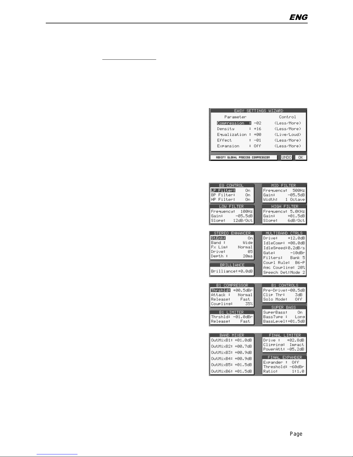
Pick out the factory pr eset whi c h best fits the desired ‘sound footpri nt’
open the 6-BAND AUDIO PROCESS BLOCK and then click
the WIZARD tab
Enter the WIZARD screen. A lter the listed Macroparameters
very slowly while li stening how the original output sound
modifies. When satisfied with the new sound, click OK. Click
UNDO to discard last modifications or ESC to quit the screen
without savi ng.
NOTE: value ranges shown in the W IZ A RD window are
tailored on the pr oc essing Pr eset being modified and do not
represent any ‘absolut e’ lim it of the Falcon 50 FM processing.
Enter the EQUALIZATION bloc k (EQ), and modify the filter
parameters fir st and then consider each filter effect by turning
it on and off from the relevant f unc tion. It is possible to set
cross-frequenc ies between filters and the amplitude of each
filter window. Click UNDO to discard last modifications or ES C
to quit the screen without saving.
Enter the STEREO ENHANCER block (SE) and alt er its
parameters at will. At the moment, keep unaltered both
Brillianc e and Multiband Controls. Click UNDO to discard l ast
modificati ons or ES C to quit the screen without saving.
Double click the BAND 1 bloc k: the SUPER BASS menu will
be shown. Alter the Bass Type and BassLevel at will and then
consider the filt er intervention by turning it on and off. Listen to
its actual effect and keep the preferred setting. Enter controls
of each Band and try to alter t heir PreDrive controls. You may
increase them by up to 1 dB, whil e You may decrem ent t hem
at will.
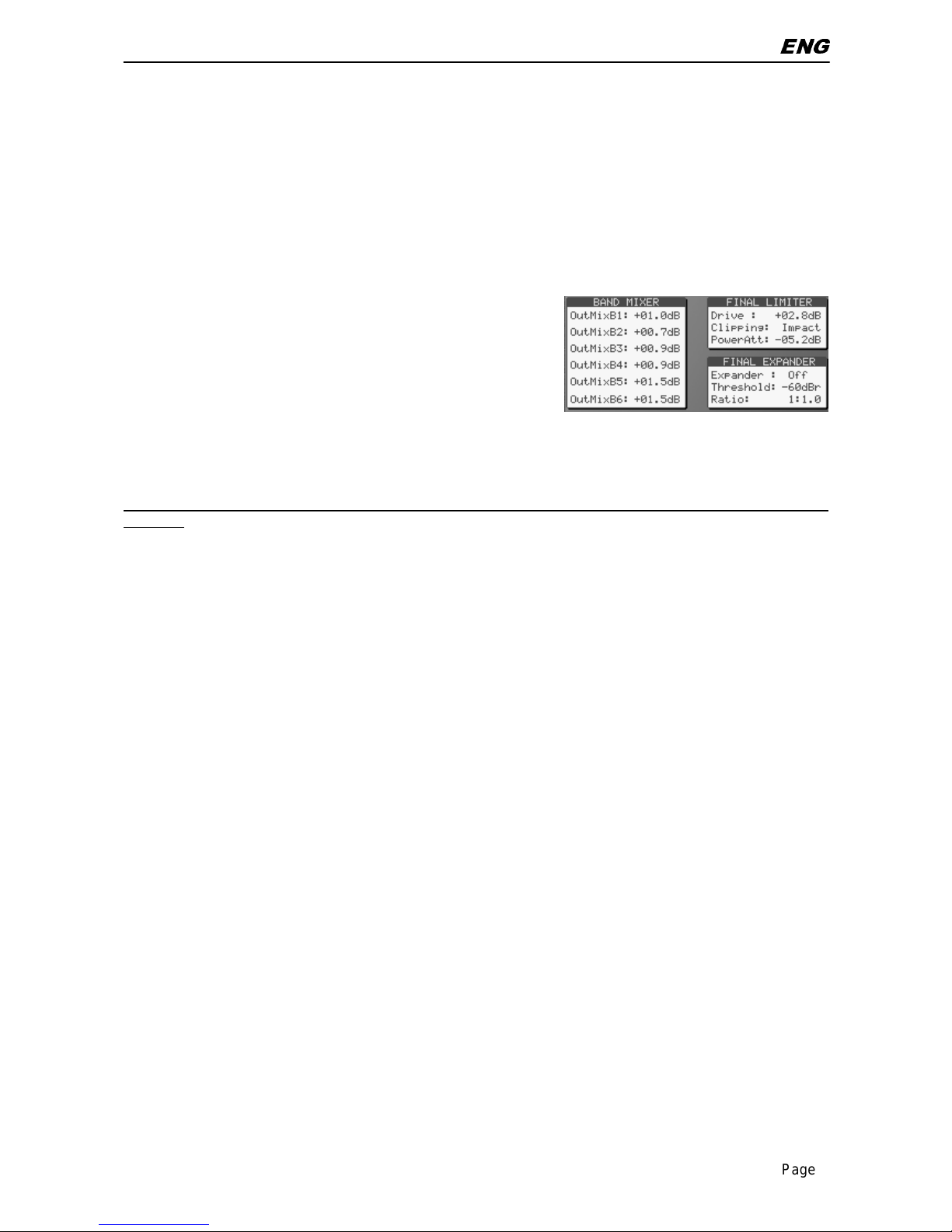
Light modific ations are also permitted in the Band Mixer stage
(Band Mixer + Final Limiter block), with increments by up to
0.5dB, while dec r em ents hav e no limi ts. Once reached the
desired sound stamp, k eep it listening carefully to for a
sufficiently long time. Also adjust the Power Attenuati on
(PowerAtt) parameter so that the PA meter on the screen acts
as little as possible whi le applying a slight attenuation. If there
still is something wrong wit h the sound (that is something
different f r om a specific sound detail) and You are unable to
find a relationshi p with any band in particular, sli ghtly reduce
the Final Limiter Drive, or switch to a more smooth Clipping
mode (f.i. from Hardest t o Har d)
Page 5
QUICK START – CREATING A NEW PRESET
ENG
Page 5
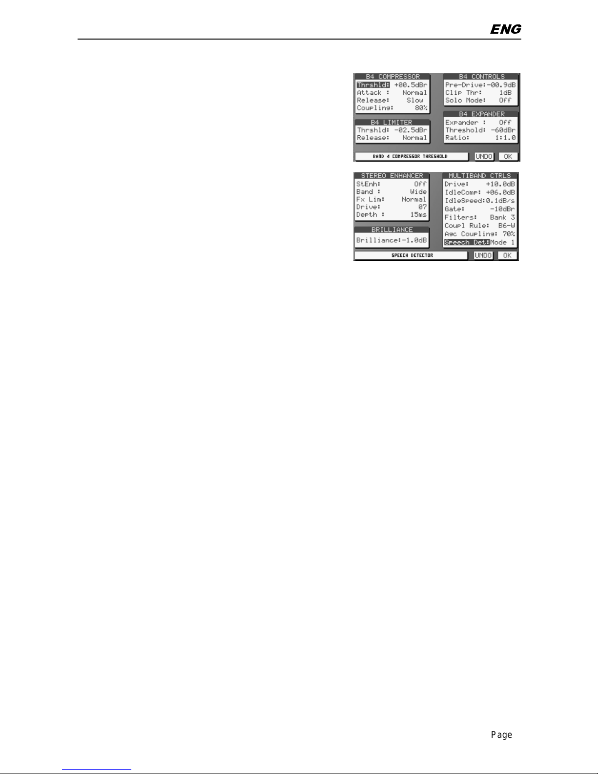
If You are abl e to det ect a specif ic sound component (f.i. a
specific instr um ent or frequency) giving bad result s on the
final output, try to ident ify the band or the bands involved and
try to reduce their LIMITER Thresholds. Use the SOLO
MODE control provided in each band in order to easier identify
the specific contribution of that band to the final output .
If live speech is fed at the input, test how the various Speech
Detector modes (i nc luded in the SE block) alter the voice
‘colour’. I n the event an external Voice/Mic Processor is used
or music only is processed, selec t MODE 1 or turn it OFF.
NOTE: the MODE 1 is the only mode completely ‘flat’ (that is,
it doesn’t alter the original freq balance in the audio to be
processed), while ot her MODE profiles change speech
equalisati on.
2.2 SETTING THE AGC & MULTI-BAND SPEEDS
Factory presets hav e been designed in or der to react in a quite slow m anner to all level variations of input
signal. Howev er, the final user may alter that behavi our at any moment. It is advisable to t o test the chosen
Preset in ‘ex treme’ condi ti ons, i.e. when the audio pro gram to be processe d contains v ery low music l evels
or very hi gh levels. If faster react ion to those audio content s is desired, modif y the AGC WINDOWS and
AGC RELEASE parameters.
It is also advi sable to increase the Thresholds of AGC Gate (GateThr) and MULTI BAND Gate parameters
(the latter one being inside the SE bloc k) in order to help the Agc stage in f r eezi ng the lowest levels not to be
enhanced.
HINTS AND TIPS: if You hav e reached a pleasant trade-off bet ween sound components with a very good
loudness having as a reference Your preferred Hi-Fi domestic tuner, amplifier and speakers set and the
result is si gnifi cantl y dif ferent when a car- radi o or a sm al l transi tor is u sed in stead, per haps You ex agerated
in ‘pumping’ very low freqs (below 100 Hz) or very high ones (10 Khz or over). In one word, it is
recommended to create Your own processing Presets having as a reference/target a specific tuner type
(home, car, portable, etc), likely the most used by the majorit y of Y our li stener s.
As a refer ence, t he so-cal led RO CK Pr esets done i n t he f ac tory are as muc h ‘univ er sal’ as pos sibl e (that i s,
they do not suff er when reproduced on small loudspakers or poor perf ormance systems), while the HOT
ones have signific ant enhancement on low and high freqs and could not fi t ev er y sound reproduc tion system.
Page 6
QUICK START – CREATING A NEW PRESET
ENG
Page 6
2.3 HOW TO CREATE AN ITU-B412 COMPLIANT PRESET FROM A NOT
COMPATIBLE ONE.
Factory Presets rangin g from 40 to 49 have been designed to meet ITU-B412 specification s.
Thus, for an ITU-compliant broadcasting , You just need to load o ne of the ITU Presets (wh ich are
directly derived from the most common not-ITU ones) and turn the MPX POWER CONTROL in the
MPX SETUP block on.
Alternatively, You may want to create an ITU-B412 compliant P r eset hav ing as a reference a Not-ITU one.
To do this, select the Pr eset* Y ou would like to begin from,
open the FINAL LIMITE R bloc k and change t he Drive control to a
value less than – 1.5 dB (- 1.8 dB suggested).
Also select the Cli pping mode = SMOOTH and regulate the
PowerAttenuati on par ameter to – 9.5 dB.
Enable the MPX POWER CONTROL in the MPX SETUP bloc k.
We suggest to listen to th e created P reset fo r a long ti me. I.e., if You will be still able to appreciate slow
and light lev el v ariations on the c reat ed Preset, reduce the Lim it er Driv e paramet er (f.i . set it to - 2. 2 dB or –
2.5 dB).
* the Preset t o begin from should be carefully se lected, as not all factory Presets are suitable for an ITU
operation
Page 7
HOW TO CHANGE THE PRESET ON AIR
ENG
Page 7
3 HOW TO CHANGE THE PRESET ON AIR
The processor has 100 curves: the factory presets (PR) are stored in posi tions 00 through 49, while positions
50 to 99 may be set by the operator.
Before creating a new custo m curve, we recommend that you careful ly evaluat e the factory p resets,
all of which are suitable for immediate on-air use given their average content of the various signal
components.
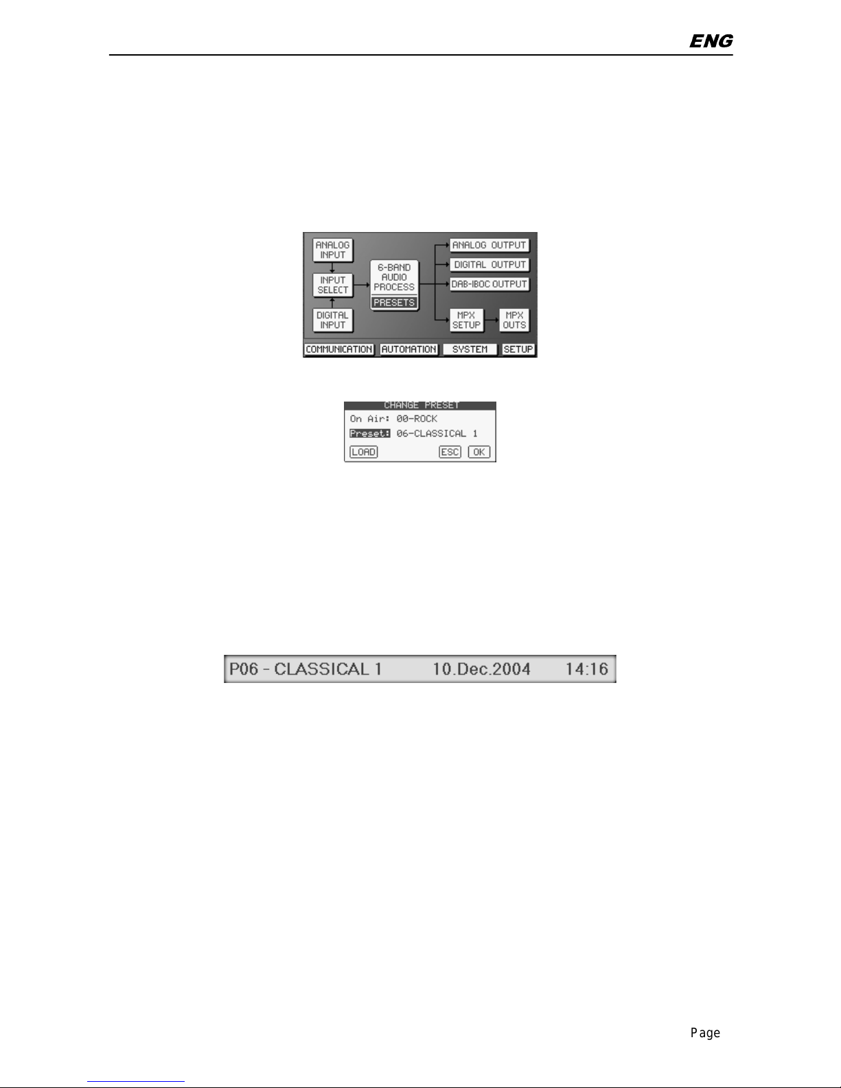
To change the Preset currently on-air, double click the PRESETS block.
The CHANGE PRESET mask shows the current P reset (On Air ), while the alternative one is shown in the
Preset field.
Using the mouse wheel or the +/- k ey s scrol l the Preset list till You reach the desired new curve.
Pressing LOAD, the new Preset will be put on air immediately, while the CHANGE PRESET screen will not
close allowing Y ou to selec t a new Preset, if desired.
Pressing OK, the new Preset will be put on air immediately, and the CHANGE PRESET screen will close.
The software screen header will now show the selcted Preset:
Page 8
SAVING A NEW PRESET
ENG
Page 8
4 SAVING A NEW PRESET
As preferred way to cr eate a new Preset, i t is advisable to pi ck up one of the existing one (ei ther Factory
done or user set) and alter it i n or der to get t he sound You want.
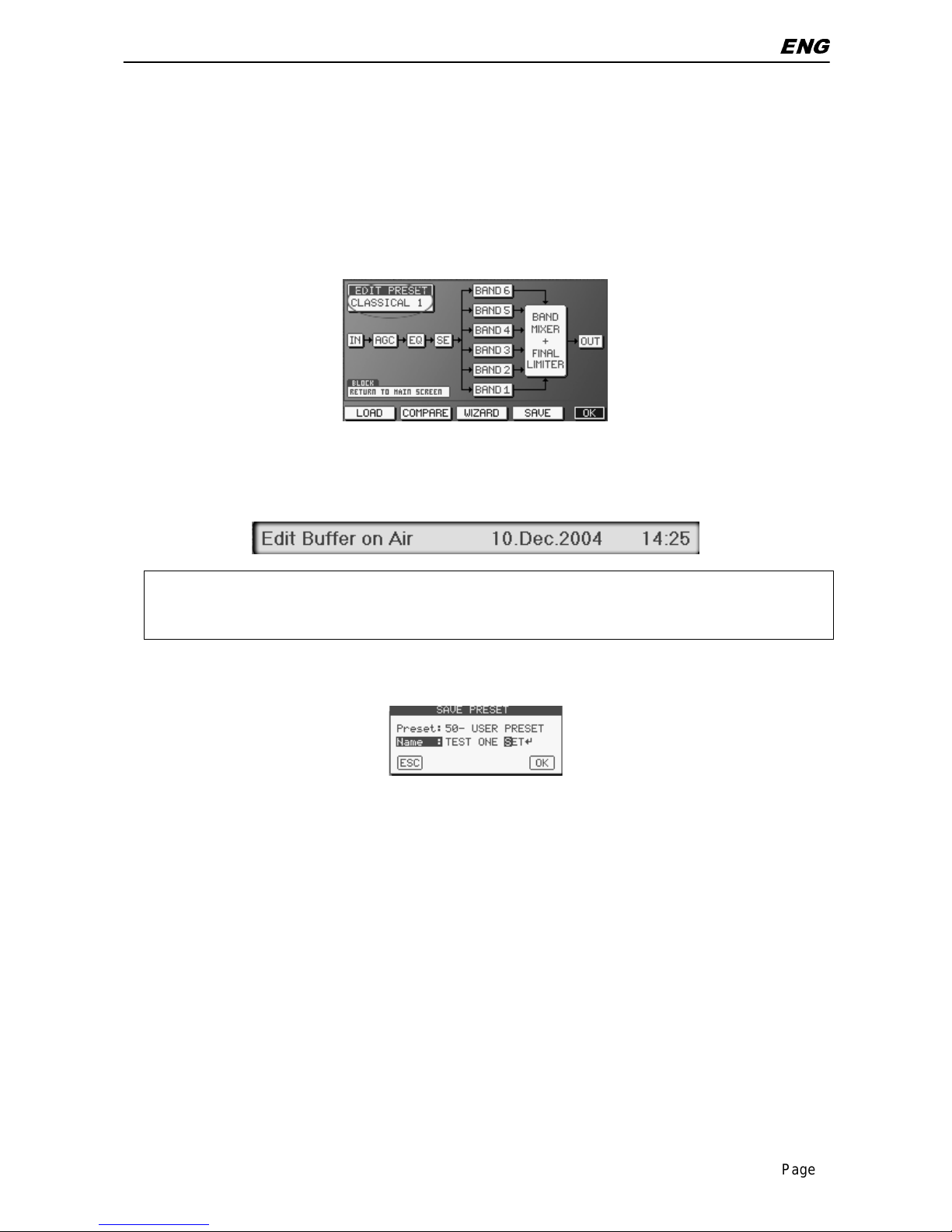
To pick up one of existing presets, refer to the previous chapter. Once the Preset is on air, doubl e cli c k the 6BAND AUDIO PROCESS block to edit it.
At the top left corner the EDIT PRES ET m enu will always prompt which Preset You are goi ng to modify.
As soon as You ent er one of t he processing bl ocks (A GC, SE, EQ, etc) and You alt er one of its param eter
(f.i. You i ncrease the AG C Release speed), the scree n header will revert to the the EDIT BUFFER ON AIR
mode, thus informi ng the user that the origi nal Preset has been modified and he/ she is currently list ening to
the modified one.
The output sound is changed i n r eal time according to the values displayed moment by moment in each
block.
Once finished the m odification task, click the SAVE button.
The SAVE PRESET window prompts You to choose the memory location where the new Preset will be
saved (locati ons fr om 50 to 99) and to ent er a menmonic nam e for that Preset.
Clicking OK the just cr eated Preset is imediately put On Air.
The same SAVE PRESET message is al so displayed every time You quit the 6-BAND AUDIO PROCESS
BLOCK after having alt er ed any par ameter.
Page 9
IMPORTING/EXPORTING AND MANAGING CONFIG FILES
ENG
Page 9
5 IMPORTING/EXPORTING AND MANAGING CONFIG FILES
5.1 EXPORTING SINGL E PRESETS, GENERAL CONFIG OR BOTH
The Falcon 50 FM c ontrol software contains speci al tools to selectiv ely export in a file (to be sav ed on Yr
local Pc, to be emailed, to be held on a CD Rom for future use, etc) a single custom preset (that is, a
processing preset c reated by the user) , all user preset s, the general equipm ent configurati on/status (that is:
input setti ng, output settings, pil ot level, passwords, e tc) or either the latter ones (all P resets + equipment
Status).
It is strongly recommended to export in afile the actual equipment STAT US as soon as
You have reached a final / good c onfiguration on the processor. This file m ust be r etained for
future use (f.i., to reload a v alid configuration after a reset, to clone the same configuration on
multiple units, etc).
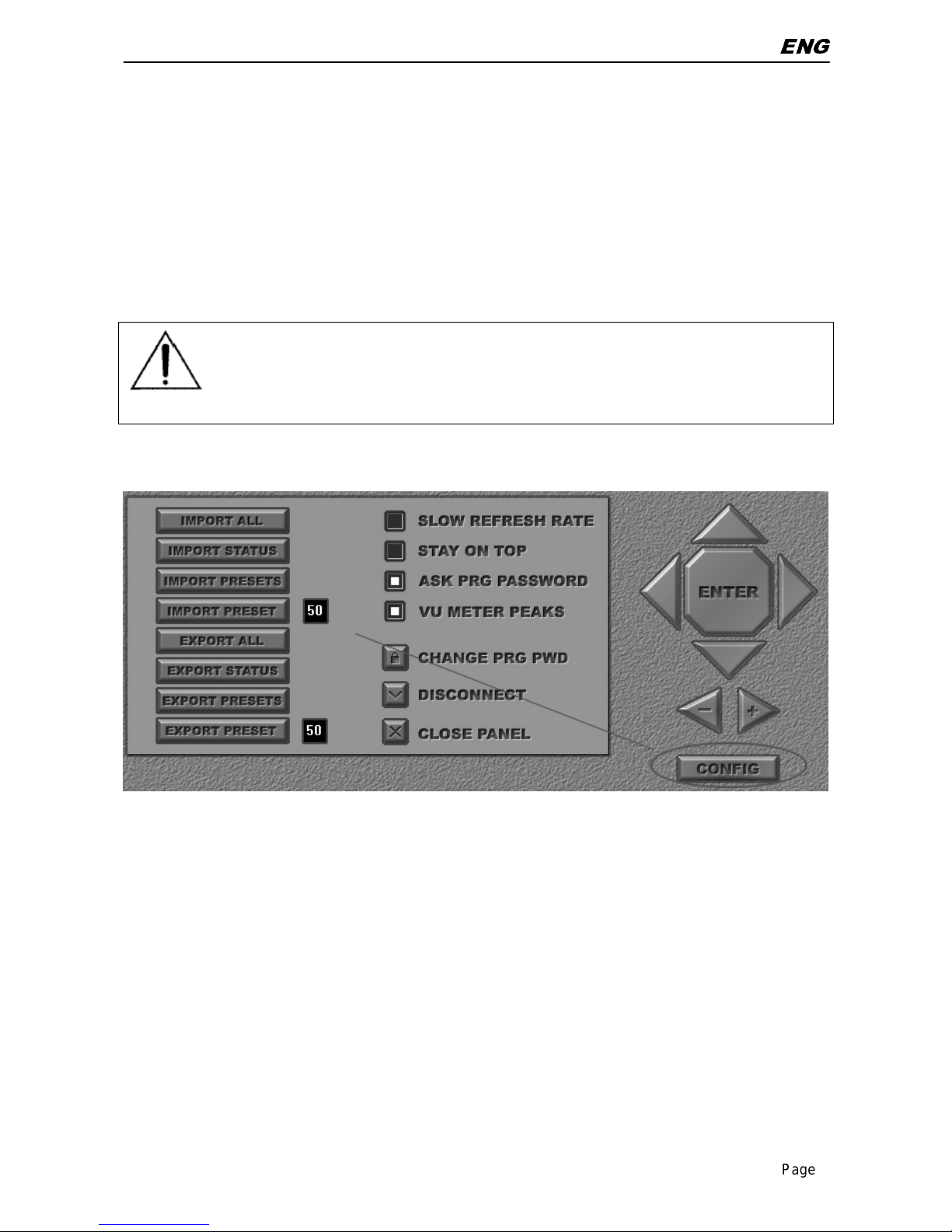
To EXPORT single presets, al l presets, Status or ‘all’ in a file, cli ck the CONFIG button on the software
screen (placed just below the large navigation buttons).
EXPORT PRESET
Exports in a file the Pr eset selected in the small black window (fr om 50 to 99)
EXPORT PRESETS
Exports in a file ALL procesing presets created by the user (from 50 to 99)
EXPORT STATUS
Exports in a file the general c onfiguration (in and out interfaces, levels, passwords,
etc) of the processor. Presets are NO T included.
EXPORT ALL
Exports in a file the general c onfiguration plus ALL user Presets (RECOM M E NDE D)
Click the desired option and save file following standard operating system procedure.
Page 10

IMPORTING/EXPORTING AND MANAGING CONFIG FILES
ENG
Page 10
5.2 IMPORTING PRESETS, GENERAL CONFIG. OR BOTH
The Falcon 50 F M control soft ware contains special tools to selectiv ely import from a f ile a single custom
preset, all user presets, a general equipment configuration/ status (that is: input setti ng, output setti ngs, pilot
level, passwords, etc ) or either the latter ones (all Presets + equipment Status).
Clik the CONFIG large button on the software screen, and then click the IMPORT buttons according to their
scope:
IMPORT PRESET
Imports a single pr oc essing P r eset from a file and places it in the memory position
according to the selec tion done in the small black window (memory posi tions from
50 to 99)
IMPORT PRESETS
Imports the whole set of 50 pr oc essing USER Presets from a file. All current User
presets will be overwritten.
IMPORT STATUS
Imports from a file t he general configuration (in and out interfaces, levels,
passwords, etc) of the proc essor. P r esets are NO T included. The current
configurati on will be lost.
IMPORT ALL
Imports from a file t he general configuration plus ALL user Presets. The whole
current configur ation and presets will be overwritt en.
Page 11

AGC OPERATION
ENG
Page 11
6 AGC OPERATION
Double Click the 6-B A ND AUDIO PROCES S bl ock on the main screen.
Double click the AGC bloc k. The AGC screen will open:
One of the most important processor function is the Automatic Gain Control (AGC) system, which
compensates for v ari ations in the input level while keeping the si gnal at its normalized internal level of 0 dBr.
Several parameters regulate the AGC function and may be modified, as shown in the AGC screen.
The bargraph indi cators displays the amount of correction in effect for long-term variations in
the program input signal.
As the Agc stage is a true t wo band stage, t hu s each of two L & R channel s is split t ed into t wo
bands.
6.1 TURNING THE AGC ON/OFF
When needed, the AGC stage can be t otally defeated by turning the Agc control to Disabled.
6.2 SETTING THE AGC SPEED
The AGC speed value is expressed in dB/ sec – i.e. the number of dB amplified or attenuated in one second.
The Falcon 50 FM allows You to set two different working speeds f or the AGC main operation: the Attack
speed and the Release speed, where the f i rst one i s norm ally signifi cantl y higher than t he second one. High
AGC Speed val ues obvi ously make it possibl e to qui ckly r ecover strong l evel diff erences, but t hey can als o
lead to unpleasant ‘ pumping’ eff ects. We suggest u sing medi um speed levels of around 1 ÷ 2 dB/sec, and
especially that you concentrate on the audio sources connect ed to the processor, to obtai n the most even
sound possible.
Page 12

AGC OPERATION
ENG
Page 12
When the AGC l evel is getti ng close to its int ernal reference l evel when releasing, the AGC will enter a so
called W ORK ZONE, where the AG C speed i s reduced t o the WZ R el val ue stated in t he AGC WI NDOWS
menu.
The dimension of the WORK Zone i s stated by the WZ Thr (Work Zone Threshold) parameter.
The WORK ZONE interv al (whic h ranges f rom t he negative lev el ex pressed by the WZ Thr paramet er to the
0 dBr internal reference) has been intr oduced because high c ompression and high am plification speed on
the whole band could engender unpleasant pumping effects.
The Attack speed sets the speed the AG C will use to react to sudden and unaxpected transient of input
signal (exceeding 0 dBr), which could bring to improper, lar ge increment of output level.
Basically, the Att ac k time should be set according to the music content s and ty pe (Cl assic al, Rock, etc) being
broadcast.
EXAMPLE 1 – SETTING AGC SPEEDS FOR GENERAL PURPOSE OPERATION
Having set AGC Rel ease speed = + 2 dB/sec and WZ Thr = + 4 dB, an i nput signal of – 14 dBm will be
amplifi ed to – 4 dB in exactly 5 seconds. Once entered the Work Zone, t he approach to the 0 dBr threshold
will be slower, and equal to the WZ Rel speed. Having the latter set to 0.5 dB/sec, the whole travel will take 5
+ 8 = 13 seconds.
NOTE: this is a v ery theoricall y AGC operati on. In fact, t he MultiBand stage (f eaturing i ts own AGC contr ol)
will also contribute to normalize the level.
EXAMPLE 2 – SETTING AGC SPEEDS FOR EXTREME OPERATION
This setting i s indicated when l arge lev el gap should be com pensate in the shortest tim e. Having set AG C
Release speed = + 5 dB/sec and WZ Thr = 1 dB, an i nput signal of – 16 dBm will be amplified to – 1 dB in
exactly 3 second s. Once entered the W ork Zone, t he approach to the 0 dB r threshold will be slower, and
equal to the WZ Rel speed. Havi ng the latter set to 1 dB/sec, the whole travel wil l take 3 + 1 = 4 second s.
6.3 SETTING DRIVE, IDLE AND GATE PARAMETERS
The Agc stage may be con sidered a s a Compr essor stage wit h a posi tiv e Driv e. The Driv e v alue r epresents
the AGC Max G ain, i.e. the maxim um amplification value at tainable by t he AGC system. Thus, a Driv e not
null means AGC can increase l ow lev el s fed at its input.
EXAMPLES
Condition
Drive = 0 - having an input signal at + 8 dBr*, the AGC meter will read – 8 dB and the AGC stage will
output 0 dBr (the AGC stage i s always capable t o attenuate large signals)
- having an i nput signal at –2 dBr *, t he AGC m eter will read 0 and the AG C stage will output –
2 dBr (there is no capability to add Gain, as the Drive factor is null)
Drive = 3 - havi ng an input signal at + 8 dBr*, t he AGC meter will read – 11 dB and the AGC out put will
be 0 dBr (the AGC stage is always capable t o att enuate large signals)
- having an input signal at –2 dB r *, the AGC meter will read - 1 and the AG C stage will output 0
2 dBr (the Agc stage is able to com pensate for low signal, as Drive factor is not null)
* if the input signal is rated at the same lev el of A/D Reference, this is also the level of the s ignal being fed to
the processor.
Drive paramet er may be considered as the maximum amplification v alue att ainable by the AGC system.
For instance, setting Drive = +12 dB means that maximum amplification is +12dB: thus a –12dB signal can
be compensated to 0, whil e a –15dB si gnal will reach a maximum of –3dB.
Page 13

AGC OPERATION
ENG
Page 13
6.4 SETTING IDLE COMP, IDLE SPEED AND GATE THRESHOLD PARAMETERS
The two parameter s IDLE Comp and IDLESpeed set the behaviour of AGC stage when the input signal is
‘silent’ or it falls under the Gate Threshold (see GateThr parameter).
The Idle Comp sets the Compression rat e the AGC will reach when no signal is provided at the input .
The Idle Speed sets the AGC speed to reach t hat point.
Whit IdleSpeed = locked, t he AGC freezes at it s current status as soon as the input signal is removed or
drops under threshold.
It is advisable to set IdleComp = Drive
The GateThr parameter indi cates the threshold l evel under which the AGC system is frozen, and does not
amplify t he si gnal. While operating without the si gnal, the look- up table on the software screen visualizes the
AGC GATED status.
NB: the AGC stage wait a fixed time of 0.5 sec before intervening when the signal vari es.
6.5 SETTING CHANNEL LINKAGE AND BAND COUPLING
The AGC circuit may work with left/right channel completely correl ated, uncorrelated or parti ally correlated
(with percentage user-definable).
With L/ R Linkag e = 100 % the overall circ uit gain i s controlled by the greater of the left or right channel
signals
With L/R L inkage = 0 % the AGC control i s completely splitt ed over the two channels (i .e an indipendent
AGC control is applied to each channel).
As general rule, a percentage = 70 % may help in compensate for slight difference in l ev el s (up t o ar ound 3
dB) between input L and R channels.
In the same way, the A GC circuit may work with two band s complet ely correlated, unc orrelated or parti ally
correlated ( with percentage user-definable) .
With L/ R Linkag e = 100 % the overall circ uit gain i s controlled by the greater l ev el on the top or bottom
bands
With L/R Linkage = 0 % the AG C cont rol is com plet ely split ted ov er the two band s (i. e an indi pendent AGC
control is applied to each band, thus resulting on a kind of audi o equalization).
As general rule, a percentage = 70 % (in associ ation wit h a Crossi ng frequenc y and Cross slope between
bands well t uned on the actual audi o material to be proc essed) may help i n controlling ‘dr um beats’ or low
frequency ‘punch’ music components whch may alter AGC operati on on higher frequencies.
Page 14

THE PRESET LIST
ENG
Page 14
7 THE PRESET LIST
N° NAME SCOPE DENSITY DEFINITION
00 Rock (default) General Purpose Mid High
01 Adult Contemp General Purpose Low Very High
02 Hot AC General Purpose Mid Mid
03 Purist General Purpose Mid High
04 Soft AC General Purpose Mid Mid
05 W ide Effect Effect Evaluation Mid-High Low
06 Classical 1 Classical Music Very Low High
07 Classical 2 Classical Music Low High
08 Clean&Smooth General Purpose Mid High
09 Country 1 Live & Acustic Mid-High Mid
10 Country 2 Live & Acustic Mid-High Mid
11 Jazz Jazz Music Low High
12 Modern Rock General Purpose Mid Mid
13 Phat One General Purpose High Low
14 Solid Gold General Purpose High Low
15 Talk Talk Radio Mid Mid
16 Urban Disco-House-Urban Mid-High Mid
17 Oldies General Purpose Mid-High Mid
18 Factory Test -------------------- ------------ -------19
Soft Rock General Purpose Mid High
20
Hot Compress General Purpose High Mid
21
RockCompress General Purpose High Low
22
WideCompress General Purpose High Low
23
UrbanCompress
Disco-House-Urban
High Low
24
Rock Live General P ur pose High Mid
25
Hot Live General Purpose High Mid
26
Wide Live General Purpose High Mid
27 Empty Empty Empty Empty
28 Empty Empty Empty Empty
29 Empty Empty Empty Empty
30 Empty Empty Empty Empty
31 Empty Empty Empty Empty
32 Empty Empty Empty Empty
33 Empty Empty Empty Empty
34 Empty Empty Empty Empty
35 Empty Empty Empty Empty
36 Empty Empty Empty Empty
37 Empty Empty Empty Empty
38 Empty Empty Empty Empty
39 Empty Empty Empty Empty
40 Rock ITU General Purpose Very Low High
41 Hot AC ITU General Purpose Very Low High
42 Soft AC ITU General Purpose Very Low High
43 Purist ITU General Purpose Very Low High
44 Classic ITU Classical Music Very Low High
45 Country ITU Live & Acustic Very Low High
46 Jazz ITU Jazz Music Very Low High
47 Talk ITU Talk Radio Very Low High
48 Urban ITU Disco-House-Urban Very Low High
49 Oldies ITU General Purpose Very Low High
50 Rock ITU General Purpose Very Low High
Page 15

THE PRESET LIST
ENG
Page 15
NOTE: The Speech Detecto r stage is set as ENABLED w ith all the factory Preset s (even i f at differen t
modes/levels). It may be advisable to turn the Speech detector Off when using an external Voice
Processor / Mic Processor (oppure usarlo nella modalita’ 1 in modo da usufruire della funzione
Stereo Enhacer auto_off).
7.1 SPEECH DETECTOR – MODE TABLE
BAND1 BAND2 BAND3 BAND4 BAND5 BAND6 STEREO_ENH
MODE 1 0dB 0dB 0dB 0dB 0dB 0dB AUTO_OFF
MODE 2 0dB 0dB 0dB 0dB +2dB +3dB AUTO_OFF
MODE 3 0dB 0dB 0dB 0dB +2dB +4dB AUTO_OFF
MODE 4 0dB 0dB 0dB + 2dB +2dB +4dB AUT O_OFF
MODE 5 0dB 0dB 0dB + 2dB +3dB +6dB AUT O_OFF
MODE 6 0dB 0dB 0dB + 3dB +6dB +4dB AUT O_OFF
MODE 7 0dB 0dB 0dB + 3dB +6dB +4dB AUT O_OFF
MODE 8 0dB 0dB +2dB +5dB +6dB +6dB AUTO_OFF
MODE 9 0dB 0dB +2dB +5dB +6dB +6dB AUTO_OFF
Page 16

APPENDIX A
ENG
Page 16
APPENDIX A
7.2 SYSTEM EVENTS
Using the event logs in Ev ent Viewer, y ou c an gather information about major problem s or events occurred
during the equi pm ent lif e or from the last general hardware reset.
In order not to fill the Logger mem or y in extra-fast way, for events of the same natur e only Tim e and Date will
be updated.
The presence of hardware errors will help the administrator in knowing the cause of them or in getting faster
repairing servic e. The logger also shows if and when the system has been turned of f/on and if Alarm
conditions arised.
To access the EVENTS LOG Screen, click the SYSTEM tab:
and then the EVENTS page:
The EVENTS screen contain the last 20 system events, with relevant Time and Date
Possible event s are:
"NO PRIMARY INPUT SOURCE "
"SYS CLOCK SYNCHRONIZATION"
"TEMPERATURE OVER 60°C "
"SYS CLOCK FAILURE "
"TEMPERATURE OVER 70°C "
"DSP 0 FAILURE "
"DIGITAL INPUT FAILURE "
"DSP 1 FAILURE "
"DIGITAL OUTPUT FAILURE "
"DSP 2 FAILURE "
"ALARM CONDITION "
"DSP 3 FAILURE "
"UART 1 FAILURE (RS-232) "
"NOT VOLATILE MEM FAILURE "
"UART 2 FAILURE (REAR USB)"
"ETHERNET FAILURE "
"UART 3 FAILURE(FRONT USB)"
"UNRECOGNIZED FAULT "
"UART 4 FAILURE (TCP/IP) "
"SYSTEM STATUS RESET "
Page 17

APPENDIX A
ENG
Page 17
7.3 GENERAL SYSTEM RESET
This document describes the procedure to perform a general har dware Re set.
7.3.1 BEFORE BEGINNING
WARNING!
Save your presets! Th is reset p roced ure will cause all of you r preset s to be d efinitel y
erased. If you h ave a computer w ith Pc Control Softw are installed, transfer th em to
the computer as described in the manual (EXPORT ALL procedure).
If you don't, write down the settings for each parameter.
7.3.2 RESET PROCEDURE
REMOVE POWER from the Falcon 50 FM by disconnecting the AC power cord. Disconnect all other
cables to make access conv enient.
REMOVE the TOP COVER from the unit by removi ng the phillips screws around the peripher y of t he
cover.
PLACE the UNIT in front of you with the FRONT PANEL facing you. All instructions are described
and/or shown with the unit in this position
Locate the jumper mar k ed JP1 on the left of the main board (see diagram here below).
Page 18

APPENDIX A
ENG
Page 18
Reconnect the AC power cord t o the rear of the unit.
Switch the equi pm ent On
set the jumper JP1 to its LEFT (external) posit ion: as soon as the Jumper will be set, the three front
LEDs OPERATE, PC-LINK and ALARM will light firmly
Remove and set again the Jum per i n its Left posi tion quickly: the OPERATE LED will turn Off
Now, remove and quickly set again the Jumper in its Left position: the PC- LINK LE D will also tur n Of f
As third step, rem ov e and set again the Jumper in its Left position very fast: all LE Ds will star t blinking
At this moment, the Reset has not been alr eady performed and You still have a ‘back door’ to get the
system back to work without loosing its current confi guration. In the event You would like not to reset
the unit any more, switch off and then on again. If You want to still reset the unit, wait til l the end of
blinking sequence: as soon as the O P E RA TE LE D will resume to blink, the generale reset is
successfully performed.
Page 19

APPENDIX B – BLOCK DIAGRAMS OF SINGLE STAGES
ENG
Page 19
8 APPENDIX B – BLOCK DIAGRAMS OF SINGLE STAGES
8.1 ANALOGIC INPUT
A/D
CONVERTER
PHASE
ROTATOR
30 Hz HP
FILTER
CLIPPING
POINT
REFERENCE
{ Off, Level 1, Level
2, Level 3 }
{ Off, On }
A/D
CONVERTER
PHASE
ROTATOR
30 Hz HP
FILTER
CLIPPING
POINT
REFERENCE
{ Off, Level 1, Level
2, Level 3 }
{ Off, On }
x
x
INPUTCOMMUT
ATIONMATRIX
SWA
P
L
/
RINVERTLINVERTR
{ Stereo,
Mono L,
Mono R,
Mono L+R
}
InputLInput
R
L
R
T
O
A
G
C
S
T
A
G
E
Analogic Input
15 KHz
LP FILTER
15 KHz
LP FILTER
8.2 DIGITAL INPUT
DIGITAL
INTERFACE
PHASE
ROTATOR
30 Hz HP
FILTER
RESOLUTION REFERENCE
{ Off, Level 1, Level
2, Level 3 }
{ Off, On }
DIGITAL
INTERFACE
PHASE
ROTATOR
30 Hz HP
FILTER
RESOLUTION REFERENCE
{ Off, Level 1, Level
2, Level 3 }
{ Off, On }
x
x
INPUTCOMMUTATIONMATRI
X
SWA
P
L/RIN
VERTLINVERT
R
{ Stereo,
Mono L,
Mono R,
Mono L+R
}
InputLInput
R
L
R
T
O
A
G
C
S
T
A
G
E
Digi tal In put
15 KHz
LP FILTER
15 KHz
LP FILTER
Page 20

APPENDIX B – BLOCK DIAGRAMS OF SINGLE STAGES
ENG
Page 20
8.3 DUAL BAND AGC
CROSS
POINT
FREQUENCY
FILTER
SLOPE
RMS
RMS
COMPRESSION
CONTROL
L/R
LINKAGE
DRIVE
DRIVE
{0.0,…,+20.0
dB}
{0,…,100%}
BAND
COUPLING
{0,…,10 0%}
CROSS
POINT
FREQUENCY
FILTER
SLOPE
RMS
RMS
COMPRESSION
CONTROL
DRIVE
DRIVE
{0.0,…,+20.0
dB}
BAND
COUPLING
{0,…,10 0%}
RMS
AVG
LEFT
INPUT
RIGHT
INPUT
T
O
EQUALIZER
T
O
EQUALIZER
Dual Band Stereo
AGC
8.4 STEREO ENHANCER
FILTER
GATE
DIGITAL
DELAY
EFFECT
MEASUREMENT
Limiter
LEVEL
+++
+
-
-
+
+
Input
R
Input
L
Output
R
Output
L
DRIVE DEPTH
Digi tal Ster eo
Enhancer
Page 21

APPENDIX B – BLOCK DIAGRAMS OF SINGLE STAGES
ENG
Page 21
8.5 BAND 1 COMPRESSOR - LIMITER
BAND 1
FILTER
BAND 1
COMPRESSOR
BANK
SELECTION
FROM STEREO ENHANCE
R
BAND 1 COMPRESSOR LIMITER
STAGE
THRESHOLD
COUPLING
ATTACK
RELEASE
PRE-DRIVE
BAND 1
LIMITER
THRESHOLD ATTACK
RELEASE
BAND 1
CLIPPER
LIMITER THRESHOLD
&
CLIPPING POINT
BAND 1
EXPANDER
THRESHOLD
RATIO
BAND 1
FILTER
BANK
SELECTION
T
O
B
A
N
D
M
I
X
E
R
SUPER
BASS
FILTER
SUPER BASS
TYPE
SUPER
BASS
COMPRESSOR
COMPRESSOR
THRESHOLD
SUPER
BASS
8.6 BAND 2 COMPRESSOR - LIMITER
8.7 BAND 3 COMPRESSOR - LIMITER
BAND 3
FILTER
BAND 3
COMPRESSOR
BANK
SELECTION
FROM STEREO ENHANCE
R
BAND 3 CO MPRESSOR LIM ITER
STAGE
THRESHOLD
COUPLING
ATTACK
RELEASE
PRE-DRIVE
BAND 3
LIMITER
THRESHOLD ATTACK
RELEASE
BAND 3
CLIPPER
LIMITER
THRESHOLD & CLIPPING POINT
BAND 3
EXPANDER
THRESHOLD
RATIO
BAND 3
FILTER
BANK
SELECTION
T
O
B
A
N
D
M
I
X
E
R
Page 22

APPENDIX B – BLOCK DIAGRAMS OF SINGLE STAGES
ENG
Page 22
8.8 BAND 4 COMPRESSOR - LIMITER
BAND 4
FILTER
BAND 4
COMPRESSOR
BANK
SELECTION
FROM STEREO ENHANCE
R
BAND 4 CO MPRESSOR LIM ITER
STAGE
THRESHOLD
COUPLING
ATTACK
RELEASE
PRE-DRIVE
BAND 4
LIMITER
THRESHOLD ATTACK
RELEASE
BAND 4
CLIPPER
LIMITER
THRESHOLD & CLIPPING POINT
BAND 4
EXPANDER
THRESHOLD
RATIO
BAND 4
FILTER
BANK
SELECTION
T
O
B
A
N
D
M
I
X
E
R
8.9 BAND 5 COMPRESSOR – LIMITER
BAND 5
FILTER
BAND 5
COMPRESSOR
BANK
SELECTION
FRO
M STEREO EN
HANCE
R
BAND 5 CO MPRESSOR LIM ITER
STAGE
THRESHOLD
COUPLING
ATTACK
RELEASE
PRE-DRIVE
BAND 5
LIMITER
THRESHOLD ATTACK
RELEASE
BAND 5
CLIPPER
LIMITER
THRESHOLD & CLIPPING POINT
BAND 5
EXPANDER
THRESHOLD
RATIO
BAND 5
FILTER
BANK
SELECTION
T
O
B
A
N
D
M
I
X
E
R
8.10 BAND 6 COMPRESSOR – LIMITER
BAND 6
FILTER
BAND 6
COMPRESSOR
BANK
SELECTION
FROM STEREO ENHANCE
R
BAND 6 CO MPRESSOR LIM ITER
STAGE
THRESHOLD
COUPLING
ATTACK
RELEASE
PRE-DRIVE
BAND 6
LIMITER
THRESHOLD ATTACK
RELEASE
BAND 6
CLIPPER
LIMITER
THRESHOLD & CLIPPING POINT
BAND 6
EXPANDER
THRESHOLD
RATIO
BAND 6
FILTER
BANK
SELECTION
T
O
B
A
N
D
M
I
X
E
R
Page 23

APPENDIX B – BLOCK DIAGRAMS OF SINGLE STAGES
ENG
Page 23
8.11 FINAL LIMITER
EMPHASIS
HF
LIMITER
PHASE
ADJUST
DELAY
HF
CLIPPER
LOOK-AHEAD
LIMITER
CLIPPING
MODE
{ 50uS,
75uS }
{ 50uS,
75uS }
BRILLIANCE
{ 50uS,
75uS }
15 KHz
LP
(LA
Meter)
(HF
Meter)
OutMixB1
OutMixB6
FINAL
EXPANDER
POWER
LIMITER
(PAMeter)
FINAL
MID-HIGH
LIMITER
FINAL
BASS
LIMITER
CLIPPING
MODE
CLIPPING
MODE
CLIPPING
MODE
(MF
Meter)
(BF
Meter)
CLIPPING
MODE
THRESHOLD,
RATIO
FROMMULTIBAND
S
P
R
O
C
E
S
S
O
R
S
I
G
N
A
L
FINAL LIMITER
LIMITER
DRIVE
Page 24

APPENDIX C - MEASUREMENTS
ENG
Page 24
9 APPENDIX C - MEASUREMENTS
9.1 BYPASS PERFORMANCE
AUDIO TESTS STRUMENTATION:
ANALOGIC MEASURES : NEUTRIK MINILYZER ML1
NEUTRIK MINIRATOR MR1
DIGITAL MEASURES: NEUTRI K DIGILIZER DL1
BYPASS SYSTEM PERFORMANCE: S/N
ANALOGIC INP – ANALOGIC OUT -99.1dB (-102.3 A-WTD) CLIP 18.0dBu – REF 0.0dBu
ANALOGIC INP – DIGITAL OUT -103.5dB(-105.8 A-WTD) CLIP 18.0dBu – REF 0.0dBu
DIGITAL INP – ANALOGIC OUT -101.3dB(-102.6 A-WTD) CLIP 18.0dBu – REF 0.0dBu
DIGITAL INP – DIGITAL OUT -124.3dB(-126.8 A-WTD)
BYPASS SYSTEM PERFORMANCE: BAND
ANALOGIC INP – ANALOGIC OUT -0.15dB(30Hz), -0.15dB(14.9Khz), -50dB(16.5Khz)
ANALOGIC INP – DIGITAL OUT -0.15dB(30Hz), -0.15dB(14.9Khz), -50dB(16.5Khz)
DIGITAL INP – ANALOGIC OUT -0.15dB(30Hz), -0.15dB(14.9Khz), -50dB(16.5Khz)
DIGITAL INP – DIGITAL OUT -0.15dB(30Hz), -0.15dB(14.9Khz), -50dB(16.5Khz)
BYPASS SYSTEM PERFORMANCE: DISTORSION+NOISE
ANALOGIC INP – ANALOGIC OUT Less than 0.01% (1Khz)- 10dB HeadRoom
ANALOGIC INP – DIGITAL OUT Less than 0.005% (1Khz)- 10dB HeadRoom, 24 Bit
DIGITAL INP – ANALOGIC OUT Less than 0.005% (1Khz)- 24Bit , 10dB HeadRoom
DIGITAL INP – DIGITAL OUT Less than 0.001% (1Khz)- 24 Bit, 24Bit
9.2 DYNAMIC RANGE AND DISTORTION
PROCESS ENABLED SYSTEM PERFORMANCE
DYNAMIC RANGE From 85dB to 98dB Preset Dependent
DISTORSION Preset Dependent (Typ. Less than 0.1%)
BAND Preset Dependent
9.3 MPX ENCODER INPUT FILTER
MPX ENCODER INPUT FILTER
TYPE FIR (FINITE INPULSE RESPONSE)
BAND RESPONSE -0.1dB(30Hz),-0.1dB(14.9Khz),-70dB(16.3Khz)
-100dB(19Khz)
Page 25

APPENDIX C - MEASUREMENTS
ENG
Page 25
MPX TEST
STRUMENTATION
AUDIODEVICES MPX METER MF1 SOFTWARE KIT
NATIONAL INSTRUMENT 6034E – 16 BIT ACQUISITION CARD
9.4 PILOT QUALITY AND NOISE TEST
PILOT LEVEL -20.0dBr (Referred to +12dBu 100% Modulation)
PILOT FREQUENCY 19000.34Hz (at 23° Celsius)
PILOT DISTORSION 0.008% ( on 100Khz Band)
PILOT DISTORSION+NOISE 0.078% ( on 100Khz Band)
NOISE -88dBr ( on 100Khz Band, Referred to 100% Mod)
TEST CONDICTIONS OUT LEVEL = +12dBu, LOAD=600Ohm, PILOT LEV= -20dB
MPX SOURCE= INPUT, MODE=STEREO
9.5 PILOT PROTECTION TEST (MPX CL IPPER OFF)
PILOT PROTECTION 78. 3dB (WINDOW FROM 17Khz to 21Khz, Referred to 6.9% Pilot
injection)
NOTE: MEASURE PRESET INDEPENDENT
TEST CONDITIONS
OUT LEVEL = +12dBu, LOAD=600Ohm, PILOT LEV=-20dB
MPX SOURCE= PROC , MODE=STEREO, MPX CLIPPER=OFF
Page 26

APPENDIX C - MEASUREMENTS
ENG
Page 26
9.6 PILOT PROTECTION TEST (MPX CL IPPER ON)
PILOT PROTECTION 67. 8dB (WINDOW FROM 17Khz to 21Khz, Referred to 6.9% Pilot
injection)
TEST CONDITIONS
OUT LEVEL = +12dBu, LOAD=600Ohm, PILOT LEV=-20dB
MPX SOURCE= PROC , MODE=STEREO, MPX CLIPPER=100%
PRESET= ROCK (PRESET 0)
9.7 RDS PROTECTION TEST (MPX CLIPPER O N)
RDS PROTECTION 53.2dB (WINDOW FROM 55Khz to 59Khz, Referred to 3% Rds
injection)
TEST CONDICTIONS
OUT LEVEL = +12dBu, LOAD=600Ohm, PILOT LEV=-20dB
MPX SOURCE= PROC , MODE=STEREO, MPX CLIPPER=100%
PRESET= ROCK (PRESET 0)
Page 27

APPENDIX C - MEASUREMENTS
ENG
Page 27
9.8 STEREO SEPARATION TEST
STEREO SEPARATION
75.2dB (30Hz), 74.9dB( 100Hz ) , 75. 4dB ( 1K hz),
76.1dB(10Khz), 72.3dB(15Khz)
TEST CONDITIONS
OUT LEVEL = +12dBu, LOAD=600Ohm, PILOT LEV=-20dB
MPX SOURCE= INP , MODE=STEREO, MPX CLIPPER=100%
9.9 MAIN TO SUB TEST
MAIN TO SUB
76.2dB (30Hz), 75.9dB(100Hz), 75.8dB(1Khz),
71.3dB(10Khz), 68.3dB( 15K hz )
TEST CONDITIONS
OUT LEVEL = +12dBu, LOAD=600Ohm, PILOT LEV=-20dB
MPX SOURCE= INP , MODE=STEREO, MPX CLIPPER=100%
Page 28

APPENDIX C - MEASUREMENTS
ENG
Page 28
9.10 MPX DEVIATION TEST (MPX CLIPPER OFF)
MAX DEVIATION
78.8Khz (a 3-4Khz error from reference allow to set an external Mpx Clipper
to the suggested cli pping point). Usefull in partic ol ar on the Analogic Audio
Output to reach equivalent performance to the internal MpxClipper when an
external mpx clipper is used.
TEST CONDITIONS
OUT LEVEL = +12dBu, LOAD=600Ohm, PILOT LEV=-20dB
REFERENCE= GENERATOR (1Khz, LEFT=RIGHT, 100% Modulation)
MPX SOURCE= PROC, MODE=STEREO, MPX CLIPPER=Off
9.11 MPX DEVIATION TEST (MPX CLIPPER ON)
MAX DEVIATION 75.8Khz
TEST CONDITIONS
OUT LEVEL = +12dBu, LOAD=600Ohm, PILOT LEV=-20dB
REFERENCE= GENERATOR (1Khz, LEFT=RIGHT, 100% Modulation)
MPX SOURCE= PROC, MODE=STEREO, MPX CLIPPER=100%
Page 29

TECHNICAL SPECIFICATIONS
ENG
Page 29
10 TECHNICAL SPECIFICATIONS
GENERAL
Dimensions 3 rack unit, 352 x 483 x 132 mm ~ AC Rate 230 Vac 50 Hz / 110 Vac 60 Hz +/-10%
Weight Around 7 Kg Power consumption 25 VA
ANALOG AUDIO INPUT DIGITAL AUDIO INPUT
Convers i on 24 bit Sigm a-Delta (Cr yst al C S4 272)
Connect or T yp e XLR female & optical tos/ li nk
Connector Type XLR female el. Balanced - EMI –suppressed
Formats AES3/EBU
Nominal Level adj - 10.0dBu to +15.0dBu (0.1dBu step)
Input Rates
32/44.1/48/64/88.2/96KHz with automatic
selection and jitter correction
AD Clipping Point 0.0dBu to 24.0dBu (0.1dBu Step)
Nominal Lev el ad j From 0.0dBFs t o –25 dBFs (0.1dBu S t ep)
AD Dynam. Range 104 dB RMS (107dB A weighted)
Dynamic Range 125dB (Typ), 122dB (Min)
Impeda nce 600Ohm / 10KOhm
Resolution
16 / 20 / 24 bit
Input Modes
Stereo, Mono L+R, Mono L, Mono R, L/R
Swapped, separated R & L polarity inversion
Input Modes
Stereo, Mono L+R, Mono L, Mono R, L/R
Swapped, separated R & L polarity inversion
Phase Rotator & Hi
Pass Filter
Selectable & Configurable separately from
Dig ital Input
Phase Rotator & Hi
Pass Filter
Selectable & Configurable separately from
Analog Input
ANALOG AUDIO OUTPUT DIGITAL AUDIO OUTPUT
Convers i on 24 bit Sigm a-Delta (Cr yst al C S4 272)
Connector Type XLR male & optical tos/link
Connector Type XLR male el. Balanced - EMI –suppressed
Formats AES3/EBU, IEC60958, EIAJCP1201
Nominal Level -5.0 dBu to +20.0dBu (0.1dBu step)
Sample Rates
32/44.1/48/64/88.2/96KHz internal or
synchronized to Digital Input / AES-EBU
SYNC Input
Source Impedance 50 Ohm
Output Level From 0.0 dBFs To –2 5.0dBFs (0.1dBFs Step)
Load impedance 600 Ohm or gr eater
Resolution 16 / 20 / 24 bit
Group Delay 5 msec
Group Delay 5msec
INPUT SELECTION
(either the Analog or the Digital Input can be set as primary)
Switch Mode - Switch from a software command
Fail mode
-
No Signal on Primary input
- Switch from a remote command
- Signal und er - 30dB of n om inal value
- Switch in the event of audio failure
- Left-Right unbal > 6dB on Primary channel
Fail Time
5-60Sec (step 5 Sec)
Restore Time
1-10 Sec (step 1 Sec)
AUX IN (1,2 and 3)
SYNC-OUT
Connector Type floating BNC, EMI suppressed
Connector Type floating BNC, EMI suppressed
Leve l –20dB or 0dB Gain (jumper selectable).
Sync-Out TTL-level (5Vpp) 19 kHz Pilot Ref. Out
Input Impedance > 10 Kohm
REMOTE CONTROL (GPI) INTERFACE
REMOTE COMPUTER INTERFACES
Inputs 6 TTL level
Serial P ort s 1 x RS-232 38400 Baud
Outputs 4 TTL level
Ethe rnet interface Static IP 10/100Mbits Interface (option)
Connector SubD 25 pin
USB interface
2 Port Usb 2.0 Full Speed
Type optically decoupled
Rem. Ctrl software
Dedicated, for Win 95,98,XP,NT,2000
Page 30

TECHNICAL SPECIFICATIONS
ENG
Page 30
MPX OUTPUT MODULE
Mpx Signal, MpxClipper & Overshoot Compensator Modules are processed at 760Ksamples/sec
Conversion 24 bit ( Texas BB PCM1738)
Stereo Sep aration >70 dB typ. on the wh ol e b and ( 7 5dB@ 1Khz)
Mpx Outputs 2, with independent level controls Crosstalk M/S 70 dB
Mpx Modes Stereo, Mono, L+R, L-R, Pilot Only, No Pilot Crosstalk S/M 70 dB
Mpx Clipper On/Off & 95% - 105%, 1% Step control 38KHz suppress. > 80dB
Cmp 1 output level – 10.0dBu to +15dBu (0.1 dBu step) Pilot Protection > - 70 dB (Relative to 10% of Pilot injection)
Cmp 2 output level – 10.0dBu to +15dBu (0.1 dBu step) RDS Protection
Mod Power Limiter adjustable from –1.0dB to +12dB from ITU Ref
better than -55 dB @ 56Kh z, b ett er than
- 65dB @ 57 Khz (Mpx Clipper Disabled)
Pilot Frequency*** 19 KHz +/- 1Hz S/N >85 dB (on 60 Khz Bandwidth)
Pilot Injection –14.0 to –26.0dB (0.1dB Step) (Ref 100% Mod) Source impedance 10 Ohm
Pilot Phase Adjustable +/- 12 deg. (1 d eg st ep) Load Impedance 600 Ohm or greater
Pilot TDH+Noise 0.06% (TDH 0.00 5%) Out. Conn. type BNC floating over cha s sis, EMI sup.
Stability*** +/-10 ppm (-10 to +55 °C) Pre-emphasis
50usec, 75usec (+- 3usec adjust control
available to compensate external problems)
*** higher stability available on requ es t
BY-PASS MODE
SINE WAVE INTERNAL GENERATOR
Frequency Resp 30 Hz-15 KHz (- 0.1 dB)
Purpose Can feed eac h out pu t m odule for test
Output Noise -10 3 dB (A-weight ed)
Freq 30, 100, 400 Hz, 1Khz, 5Khz, 10Khz, 15Khz
THD 0.008% - (0.005% @ 1Khz)
Level from 0% to 120% of Modulation
Stereo Cr oss Talk > -80dB (from 30Hz to 15Khz)
Modes Left=Right, Left=-Right, Left or Right Only
Group Delay 2 ms
SOUND ENHANCING CONTROLS
PARAMETRIC EQUALIZER CONTROLS
Stereo En h ancer On/Off, Band, Depth, Limiter Thr & Drive
Low Pass Filt er On/Off, Gain & Slope
Super Bass On/Off, Bass Type & Drive
Mid Range Filter On/Off, Gain & Width
Brilliance On/Off & Level
Hi Pass Filter On/Off, Gain & Slope
*All sound enhancing and Parametric equalizer modules are processed at 47.5 Ksamples/sec.
PRESETS:
50 Factory Presets + 50 user definable
SIX BANDS MULTIRATE PROCESS* CONTROLS
BICHANNEL, DUAL BAND AGC CONTROLS
Band 1-6 Compr. Threshold, Attack & Release Speed
Hi / Lo Bands Crossover Frequency & slope
Band 1-6 Compr.
Coupling
Quantity & Rule of Compressors Coupling
Main Drive, Gate Threshold, Attack & Release
Speed, Idle Compression & Speed
Band 1-6 Limiters Threshold & R el ease Speed
Coupling Coupling between the two bands
Band 2-6 Expand. Threshold & Expansion ratio
Work zone Threshold & Release
Band 1-6 Distors.
Cancell ed C li pp er s
Thresh old ad jus table
(Clip Mode for Band1 Only)
L/R Linkage 0- 100 %
Band 1-6 Mixing Gain & Solo
AGC processing 47.5 Ksamples/sec
Coupling Select. 2-3-5-6 Bands-like system and more
WIZARD PANEL
Filte rs Banks Five Banks of six filte rs (preset selectable)
Density Less / More Density (+/-10)
Speech Detector automatic voice detecting
Compression Less / More (+/-10)
Equalization Warmth to Open (+/-10) Additional
MultiB and Controls
MB Gate Threshold, MB Drive, MB Idle Gain,
MB Idle Speed, MB Agc Coupl ing
Expansion Less / More (+/-10)
*Low Delay Multirate 6 band predictive not linear process (full Antialiased).
Band1 & Ban d2 are pr ocessed at 47 .5 Ks amples/sec .
Band3 & Band4 are processed at 190.0 Ksamples/sec.
Band5 & Band6 are processed at 380.0 Ksamples/sec.
DAB-IBOC OUTPUT MODULE (OPTIONAL)
DAB-IBOC MODULE CONTROLS
Connectors XLR male & optical tos/link Low Pass Filter On/Off, Gain & Slope
Formats AES3/EBU Mid Range Filter On/Off, Gain & Width
Sample Rates the same as the Digital audio Output Hi range Filter On/Off, Gain & Slope
Output Level 0.0 dBFs to – 25.0dBFs (0.1dBFs Step) LookAhead Limiter Drive & LookAhead Time
Group Delay 5 ms Overshoot Comp. On/Off
*All DAB Par am et r ic equalizer filt er s are processed at 47.5 Ksamp l es /s ec.
*The LookAhead Final Limiter & The Overshoot Compensator are processed at 190 Ksamples/sec
AC MAINS FUSE
Ratings 315 mA (for 230 Vac), 640 mA (for 115 Vac) Type Timed (slow blow)
Dimensions 5 x 20 mm glass tube
 Loading...