

Page 1
Page 2

Page 1
Contents
1 Technical Parameters .............................................................................................................................................. 1
2 Instruction of Installation.......................................................................................................................................... 3
2.1 Instruction of External Interface Wiring ......................................................................................................... 3
2.2 Instruction of SD Card Installation ................................................................................................................. 6
3 Instruction of Using .................................................................................................................................................. 6
3.1 Instruction of Front Panel ............................................................................................................................... 6
3.2 Instruction of Remote Control Operation........................................................................................................ 7
3.3 Menu Setting Instruction: ................................................................................................................................ 9
A. Lan Setting..................................................................................................................................................15
B. 3G Setting....................................................................................................................................................16
C.WIFI Setting................................................................................................................................................17
3.4 Video Backup ................................................................................................................................................ 20
3.5 PTZ control ................................................................................................................................................... 21
3.7 Video Data Volume ...................................................................................................................................... 21
3.8 How to Build Server ...................................................................................... Error! Bookmark not defined.
1 .Technical Parameters
Items
Device parameters
Performance index
Name
Product Name
4CH 960H Mini SD Mobile DVR
4CH 720P Mini SD Mobile DVR
System
Operation System
Linux
Operation Interface
Graphical Interfaces, Chinese/English optional
File System
Proprietary Format
System Privileges
User Password
Video
Video Input
4ch Independent Input: 1.0Vp-p,75Ω.Both B&W and Color Cameras
Video Output
1 Channel PAL/NTSC Output, 1.0Vp-p,75Ω, Composite Video Signal
Video Display
1 Or 4 Screen Display
Video Standard
PAL:25frames/Sec;NTSC:30frames/Sec
System Resources
PAL:100 Frames; NTSC:120 Frames
Audio
Audio Input
Four Channels Independent Input 600Ω
Audio Output
1 Channel(4 Channels Can Be Convert Freely)
Basic Output Level
1.0—2.2V
Distortion Plus Noise
≤-30dB
Recording Mode
Sound And Image Synchronization
Audio Compression
G711
Page 3

Page 2
Digital
Processing &
Storage
Image Compression
H.264 Fixed Code Stream
Image Format
PAL: 4*960H(960*576)
NTSC:4*960H(960*480)
Video Stream
192Kbps-2.0Mbit/s(channel)
Video Taking Up Of Hard
Disk
D1、960H:85M-675MByte/hour
720P:85MB-900MByte/hour
Playback Resolution
PAL: 1 or 4*960H(960*576)
NTSC: 1 or 4*960H(960*480)
Audio Bitrate
4KByte / s / channel
Audio Taking Up Of Hard
Disk
14MByte / hour / channel
SD Storage
Double SD card storage, Support Max 2* 128GB
Image Quality
Eight Grades to Choose
Alarm
Alarm in
4 Channels Independent Input. High Voltage Trigger
Alarm out
1 Channels Independent output
Move Detect
available
Network
Interface
Wire line Access
6pin RJ45 Port
Wifi
Built in WIFI Module, 802.11 B/G/N
GPS Interface
GPS
Built in GPS Module
Extend
Interface
RS232
Built in RS232 port for free
RS485
Built in RS485 Port for free
Intercom
Built in Intercom port for free
G-Sensor
Built in G-sensor
Others
Power Consumption
DC8-36V 5% 8W(without HDD)
Working Temperature
-20℃ ~ +85℃
Clock
Built-In Clock, Calendar
Packaging
Product Size
137(L)*132(W)*40(H)mm
Product Weight
0.6KG(without HDD)
Page 4
Page 3
2 Instruction of Installation
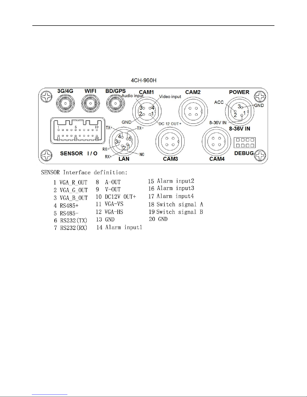
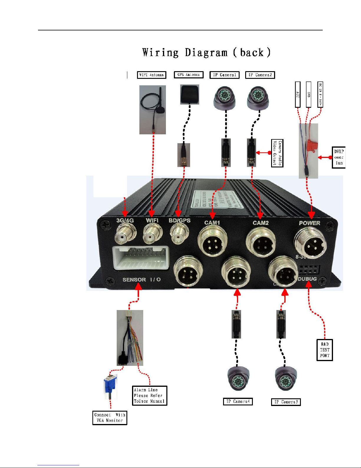
2.1 Instruction of External Interface Wiring
Remarks:
If the power supply is 12V, then the current of 12V output can be just 1A. So if there are more than
3pcs cameras, we suggest customers to get power for other cameras from the 12V vehicle power
directly or use Our special car power supply.
3G/4G 、this unit does not offer this option
Ports:
DEBUG: testing port SENSOR: alarm port
Page 5
Page 4
Page 6
Page 5
Page 7
Page 6
2.2 Instruction of SD Card Installation
Unlock the main board with key, make sure the “arrowhead” point to the left “turn on” and then
switch it to the “turn off”.
Note: The lock in the main board can also control the power. When the main board is locked, it also
means the machine starts. So before turn it on, please make sure all the cables in the system
are well connected. Otherwise the power in the car once connected, it will damage the
machine.
3 Instruction of Using
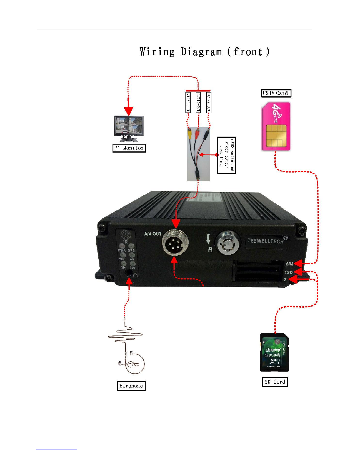
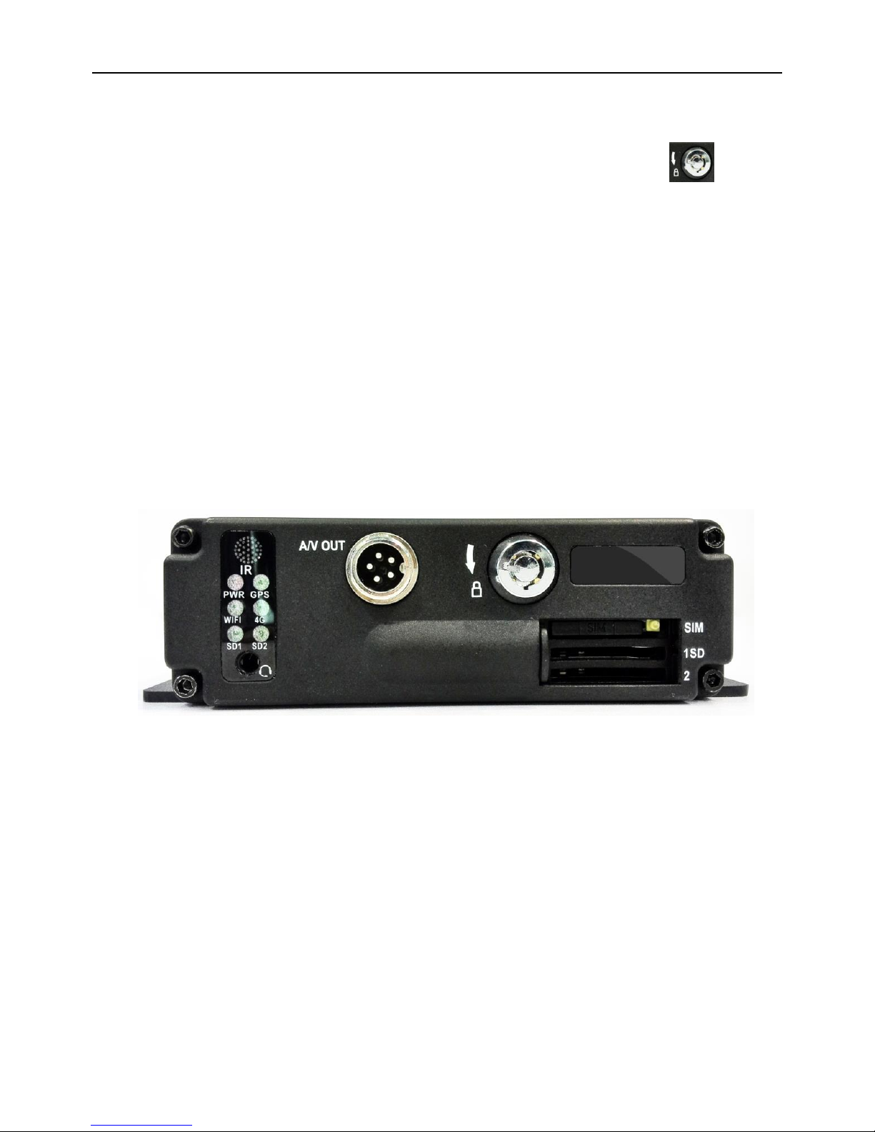
3.1 Instruction of Front Panel
LED
PWR LED: lighting while work starts. Power LED on.
GPS LED: GPS working LED indicator
4G LED: Not Available on this unit
SD1 LED: When recording, playing, backup, LED is flashing
SD2 LED: When recording, playing, backup, LED is flashing
WIFI LED: when wifi module is running the LED is on.
Key and Other Descriptions
IR: infrared receiving window.
Page 8

Page 7
LOCK: while removing the hard drive, use the key to unlock in order to remove the hard
drive, unlock after machine’s auto-disconnects the power, the power auto-connect after
being locked.
1: SD card1 slot
2: SD card2 slot
A/V OUT: Audio/ Video output, Voice intercom input
:MIC input
3.2 Instruction of Remote Control Operation
:Record
:①Lead to menu;②Return key
:Enter the submenu to do the settings and also confirm the
settings
:For playback on the mobile DVR
: ①Stop when record and playback; ②Delete key
:Pause/Play when playback
:Into PTZ control mode. (NOT AVAILABLE)
:Mute key, to turn on or turn off audio output when
playback videos with audio.(The audio input of the playback device must be connected to the
audio output of the DVR.)
:Fast-forward when video playback, play speed can be x2, x4, x8, press one time is x2,
press two times is x4, and press 3 times is x8.
:① Exit when video playback or backup. ② Exit from PTZ mode.
: Character shortcut key: Press A-B to get all characters
Page 9

Page 8
:①Upward for MENU selection. ②”UP” direction for PTZ control mode.
:①Downward for MENU selection. ②”Down” direction for PTZ control mode.
: ①Towards to left for MENU selection or MENU setup. ②”Left” direction for PTZ control
mode.
: ①Towards to right for MENU selection or MENU setup. ②”Right” direction for PTZ control
mode.
: ①screen zoom the first channel video when surveillance, record
② Enter password or set system password.
③shortcut keys, press the first key shortcut to switch the number 1, press the second
key shortcut to switch the capital letter a, press the third key shortcut toggles the lowercase
letters a, press the up and down keys to change value.
: ① screen zoom the second channel video when surveillance, record ② Enter
password or set system password.
: ① screen zoom the third channel video when surveillance, record ② Enter
password or set system password.
: ①screen zoom the fourth channel video when surveillance, record and playback ②
Enter password or set system password.
: Enter password or set system password.
: Enter password or set system password.
: Enter password or set system password.
: Enter password or set system password.
: Enter password or set system password.
: ①4 channel display when surveillance, record and playback. ②Enter password or set
system password.
Remark: When the DVR is in alarm condition, the remote control is invalid.
Page 10

Page 9
3.3 Menu Setting Instruction:
First press" "key, next press" " to enter the default password"6666",
then press“ ”to enter the main menu interface;
There are "System"、"Disk"、"Record"、"Playback"、"Network" and "Alarm"options, select the option by
pressing these buttons" , , , " ,then press " "to enter.
Basic Settings: includes options of “system setting”, “PTZ setting” ,”system info”, “vehicle
info”. .
System Setting: " Setup" and "Info "
Page 11

Page 10
Setup: Set the System time, Car Number, TV system, Language,etc.
Date format: Offer 3 display methods like “y/m/d, m/d/y, d/m/y” for personal habit.
Daylight saving time: suitable for according countries or areas.
Date: Adjust the date of HDD recorder
Time: Adjust the time of HDD recorder
Time zone: differs by countries, e.g: China for UTC+08
Language: Set "Chinese" or "English", have to restart the DVR after setting.
Video Mode: Set "PAL" or "NTSC", have to restart the DVR after setting.
Delay Time: DVR Time-lapse turn off function after the car ignition off, the default time is 5S,
and 30s,60s,120s,300s,600s,1200s,1800s,3600s,7040s all could be set,have to restart the
DVR after setting.
Speed unit: KM/H and M/H, e.g: China is KM/H
Amplifying channel: Choosing which channel to see when power on each time. This is also
useful when backing the car.
Password: Enter the default password before changing the new password(Note: You have to
Page 12

Page 11
enter the original password after press "OK", otherwise the DVR will keep staying in the
changing password status, and the remote control will not work.
New password:Enter the new password
Operating Way:
Enter the menu, press“ 、 ”to select the options ,then press“ ”to enter the
modification mode,adjust the number by pressing“ , , , ”,press“ ”to
save after adjustment。Press” ”key to exit after all settings done.
PTZ settings: Adjust and control the camera with external PTZ device.(NOT OFFERED ON
THIS UNIT)
Protocols: default PELCO-D, support PELCO-D.PELCO-
Bit rate: under RS485 port: 2400bps,4800bps,9600bps,38400bps,57600bps
Channel-Address: Channel one-Device address
Channe2-Address: Channel two-Device address
Channe3-Address: Channel three-Device address
Channe4-Address: Channel four-Device address
System Info: Display DVR hardware code number,software version information( only view,
couldn’t be changed);Reset the Factory Settings
Page 13

Page 12
Device encoding: only for this DVR, the code is unique.
Software version: the version No. of DVR software.
IMIE: IMIE No. of 3G network or module
Strength Of 3G signal: strength value:99, unknown: 0-31
Strength Of GPS signal: AA-BB(AA: GPS No.;BB: GPS strength. Show signal strength of
max.3
satellite each cycling time.
Reset the Factory Settings:
Select “Reset CFG”,there is a Reset interface after press“ ”,confirm to Reset ,cancel
to return the original interface.
Car information: details of car plate number, route and driver code.
Page 14

Page 13
Car plate number: can be showed by English, Chinese simplified language, Numbers or
common symbols.
Route: the driving route and code
Driver code: set up the driver code information
G-sensor:
GSensor-X:0000mg( default value, this value will change accordingly if the X direction
gravity accelerated speed value is changeable)
GSensor-Y:0000mg(default value, this value will change accordingly if the Y direction
gravity accelerated speed value changeable )
GSensor-Z:0000mg(default value, this value will change accordingly if the Z direction
gravity accelerated speed value is changeable)
LOG information
Page 15

Page 14
User action log, alarm logging, equipment status log
Disk:Check and format
Disk Name:Display the system recognized HDD name
Total Size: Display the total size of HDD
Free Size: Display the remaining Capacity of HDD
Format: Format HDD(only format the head files of HDD)
Select this item,there is a format interface after press“ ”,confirm to format, cancel to return
the original interface.
Record: the video files setting
单通道帧率
Page 16

Page 15
Channel: select the channel setting (the information of each channel could be set
independently)
Resolution:CIF/HD1/D1/720P;
The left side is the local storage information,
The right side is network transmission information; local “CIF,HD1,D1,720P” is optional, only
“CIF” for network transmission
Frame:1-25/30fps
The left side is local storage information,
The right side is network transmission information.
Quality:Video quality setting
The left side is the local video quality(total 8 grade,LOWEST—HIGHEST)
The right side is the network transmission quality( total 9 grades,
32kbps/48kbs/64kbps/80kbps/112kbps/144kbps/192kbps/256kbps/384kbps)
Rec mode:VIDEO ,Audio +Video(A+V),No record(N)
File Len:the packaged video files length setting
(300/600/900/1200/1500/1800/2100/2400/2700/3000/3300/3600s optional)
Save:save after finished video parameter setting (have to restart the DVR after setting.)
The operating method is similar to the "basic settings" operating
Playback: the recorded video Playback
Page 17

Page 16
There are video date in the menu, it will display the vide time after enter the date, choose the
playback time range as needed, press “Play” or click the interface “Playback “button to replay the video.
Said is power outage file suffix "_P", suffix "_S" indicates an alarm trigger video files.
Channel: 1CH/4CH Video playback;video playback on each channel or full screen, playback
and record simultaneously
Playback: Select the video files and channel to replay
Backup: Select the HDD video files backup to USB Disk
The operating method refers to “local video playback instruction”
Network Setting: LAN, 3G (NOT OFFERED), WIFI
Page 18

Page 17
LAN: connecting via RJ45
3G: NOT OFFERED ON THIS UNIT
WIFI: connecting the network of WIFI
IPC: To connect the IPC camera Settings
Local Network Setting(LAN):
Network Type: LAN
DHCP: On (Recommend)
Server IP: 219.134.190.134
Server Port: Keep it as default of 8101
Noted: If you build your own server, pls kindly input the corresponding Server IP and Server
Port, After this setting, back to video screen to restart MDVR
WIFI Setting:
Net type: select 3G-WIFI
DHCP: ON
Server IP: 219.134.190.134
Server Port: 8101
Page 19

Page 18
Noted: If you build your own server, pls kindly input the corresponding Server IP and Server
Port,
Access Network setup →“WIFI”
SSID: WIFI router device name.
Password: using password for SSID
Certificate: Support both “WPA-PSK” and “WPA2-PSK”
Encryption: Support both “CCMP” and ”TKIP”
Access router, check its “WIFI “encryption.
Page 20

Page 19
Alarm :
Alarm REC:Alarm-triggered video duration (30-330s optional,30s unit)
Positioning Interval:GPS Data upload interval, used with other system interface
Alarm out:Alarm output time (5s-900s)
Over speed:Set the over speed alarm value
Motion Detect:Open and close motion detect record and motion detect sensitivity selection
such as“off”,“high”,“medium”,“low”.Opening motion detect recording, also need to set the
icon“S”(alarm record)for time range of the detect record in “Record Setting” status except
select“High”,“Medium”,“Low”. “High”,“Medium”,“Low” is the grade of detect sensitivity, higher
grade,record easier.
DET AREA
Page 21

Page 20
:High sensitivity :Low sensitivity :No detect
Record Sequence:Set the record mode of the different time range
White blank:no record Red blank:record S blank:Alarm record
If the record mode set to“continuous recording”or alarm recording”,the remote control stop key
playback.
3.5 Video Backup
Our company System support 2 video backup ways.
1) Connect the USB disk to the DVR’s USB port for backup(Ports on Demand);Operating method as
follows:
Connect USB disk to the DVR’s USB port ( FAT32 format, backup Max.20G);
On the video playback interface, select the backup video files first, then move
to“backup”option,and press “OK”to backup, “COPY END”display after backup finished,the USB
disk could be taken away,then press” ”to exit if no other operations.
If you need to backup another files,press“ ”to repeat the previous steps to backup。
2) Take the SD card out from DVR, then connect the SD reader to the PC, you can check the video
Page 22

Page 21
playback on PC via the installed our company’s local playback analysis software .( Suitable for large
amount data backup, simple and flexible. The proprietary data files also could be converted to the
common format, suitable for different reading demands). Specifics refer to the local playback analysis
software instruction).
3.6 PTZ control
This function just used to has PTZ function models。Operations are as followings:
When DVR is working,click“ ”,entre“PTZ control”mode,If DVR has connect with screen,then on
screen’s left above would show “PTZ”,click“ ”, “ ”, “ ”, “ ”, PTZ would scroll as it
showes,the ptz camera would rotate after each command by clicking PTZ icon in the CMS or operating the
control board;Control over if wanna quit at all,click“ ”。
3.7 Video Data Volume
The required volumes of video and video-related settings ,please see the following table:
VIDEO QUALITY
Total Record
Frame
4CH 960H Data
Size Per Hour
4CH 720P Data Size
Per Hour
2.0 Mbps (HIGHEST)
100 frame
3.6GB
5.16GB
1.5 Mbps (HIGHER)
100 frame
2.65GB
3.87GB
Page 23

Page 22
1.2 Mbps HIGH(default)
100 frame
2.1GB
3.09GB
1.0 Mbps (BETTER)
100 frame
1.8GB
2.58GB
768 Kbps (NORMAL)
100 frame
1.35GB
1.93GB
512 Kbps (LOW)
100 frame
0.9GB
1.29GB
320 Kbps (LOWER)
100 frame
0.55GB
0.81GB
192 Kbps (LOWEST)
100 frame
0.335GB
0.48GB
Note: Based on users matching conditions to apply the appropriate drive and related settings.
3.8 How to Build server
1.Requirements:
Re: 1. Wan IP ( Fixed IP): The IP address is never changed.
2. A computer or a server device like Dell T320 server
3.System: Wind7,Wind8, Window server 2008 to Window server 2012
4.SQL_Server 2003,SQL_server 2005 or more
2.Build server steps,in total 9th steps:
1st Step:Settle static IP on your computer or server like the picture:
2nd step: install DVR_Server software on your computer
Page 24

Page 23
3rd step: Come into DVR_Server installation directory:
4th Step: Click “DVR Server” and “Server Install” to run them please, and them it will come out “DVR Server”
configuration file:
Page 25

Page 24
5th Steps: Open “DVR_Server configuration file, you will find there ports: 8001,8101,9001 and open the
three ports on your router:
Noted: If the three ports have been used for other things, you just need to change the ports, like
7001,6001,6101 and then open 7001,6001,6101 three ports on your router, it will be ok. Also, all the
server management will go on in the this configuration file.
6th step:Open 8001,8101,9001 ports to map your Wan IP router and restart WAN IP router
Page 26

Page 25
7th Step: After all this setting, the server should be built successfully, so that you better ask your partner
to log in the CMS software to make sure of it.
8th Steps:install the SQL_Server 2003 or SQL_Server 2005 to build your own database to use our new
Page 27

Page 26
powerful functions. And at first, pls come into DVR_Server configuration file to input your SQL IP, user
name, and password:
9th Log in CMS software and click “ ” to configurate the database:
Page 28

Page 27
Falcon Electronics LLC
3000 Custer Rd, Ste 270-542
Plano, TX 75075
972.600.1320
www.dashcam.co
 Loading...