

Page 1
Uncontrolled in hardcopy - please check for the latest version of this document online at www.apexflightops.com
Model(s)
Falcon 360-P
Firmware Version
1.0.01
Document Version
1.2
Release Date
29 Sep 2014
© 2014 Apex Flight Operations – All Rights Reserved
Page 2
1
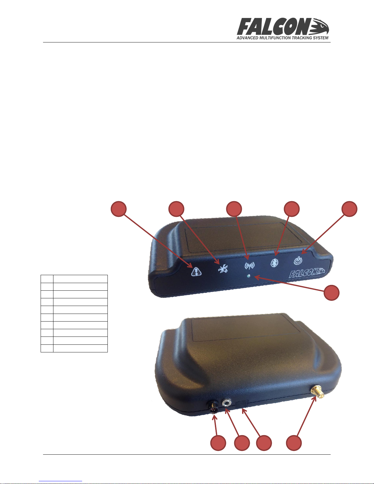
Alert Button
2
Antenna Button
3
Signal Button
4
Bluetooth Button
5
Power Button
6
Light Sensor
7
Power Connector
8
Data Port
9
Micro-USB Port
10
Antenna Connector
1 2 3 4 5
6
7 8 9
10
FALCON 360-P USER MANUAL Version 1.2
Introduction
Thank you for purchasing the Falcon 360-P – we have designed this system to provide efficient and
cost-effective tracking for your aircraft, as well as provide you with a tool for reliable
communication and data gathering during your flight operations.
The Falcon is essentially a system that gathers information from the aircraft, and requires very little
interaction from the flight crew. In normal installation and operation it will automatically track the
aircraft whenever the Avionics bus is powered.
This document describes the hardware functions, as well as installation options – for details on the
IndigoTrack Crew software application used to control the Falcon, please refer to the separate
IndigoTrack Crew User Guide.
System Components
The Falcon 360-P system consists of the tracking module which is mounted in a suitable position on
the glareshield, and a power cable which is connected to an auxiliary power supply in the aircraft.
Please refer to the Installation section for more information on installation options for the system.
The tracking module is illustrated below:
Release Date: 29 Sep 2014 © 2014 Apex Flight Operations Page 2 of 8
Page 3
FALCON 360-P USER MANUAL Version 1.2
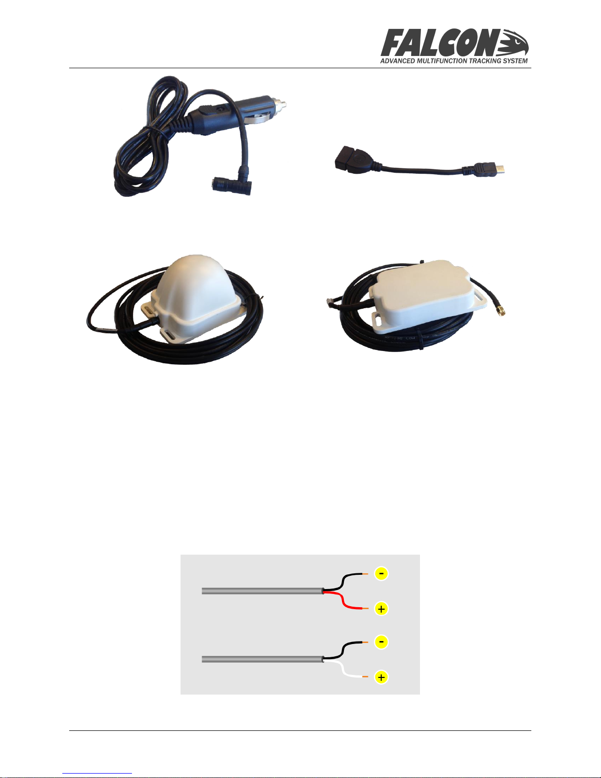
Power Cable USB Adaptor Cable
Low-Elevation Antenna or Normal Antenna
Installation
Power Cable
The Power Cable provided is has a self-locking connection to the Falcon unit to ensure that it cannot
become accidentally unplugged whilst in operation. The other side of the cable is terminated with
an Auxiliary power plug – this should be inserted into the Auxiliary Power socket in the aircraft.
If the aircraft does not have an Auxiliary Power socket, or you would prefer to have the cable
connected directly to the aircraft power, the following wiring diagram should be used by your
Aircraft Maintenance Organization to get approval for the modification to your aircraft – refer to
the color key for the cable provided with your equipment.
Release Date: 29 Sep 2014 © 2014 Apex Flight Operations Page 3 of 8
Page 4

FALCON 360-P USER MANUAL Version 1.2
Positioning the Components
The antenna component of the Falcon 360 Portable requires a view of the sky via the windshield of
the aircraft, and should be positioned so that it is as clear of obstructions as possible. Depending on
your configuration, you should take the following into account:
External Antenna
When using the portable external antenna, only the antenna needs to be positioned on the
glareshield; to avoid cluttering the glareshield, the Falcon unit itself is usually located elsewhere in
the cockpit. If the crew intends to use the Bluetooth-enabled App to control the Falcon, the unit can
even be placed completely out of sight.
Internal Antenna
When using the internal antenna of the Falcon, the unit itself should be positioned on the
glareshield.
Avoiding Possible Interference
The communication with the Inmarsat and GPS satellite constellations is hampered by metallic
obstructions, so position the antenna in the best position to avoid shadowing from the roof of the
aircraft, or the central divider (if present). The Falcon is best located on the co-pilot’s half of the
glareshield, positioned as far forward as possible. Below are some typical locations to illustrate the
best position for the Falcon unit or the external antenna:
Release Date: 29 Sep 2014 © 2014 Apex Flight Operations Page 4 of 8
Page 5

Icon
Type
Description
Button/Indicator
Triggers or Cancels the Alert Status
Button/Indicator
Shows the Antenna Status (flashes during receive or transmit)
Indicator
Satellite signal strength
Flashing
Icon
Issue and Resolution
Modem Failure – unit needs factory inspection
Antenna Failure – unit needs factory inspection
Internal storage issue – the unit will continue to function, but
no recording will take place.
Bluetooth failure – no pairing via Bluetooth is possible, but
other functions will continue to work
Internal battery failure – the unit will function whilst powered
by the aircraft, but will immediately shutdown when the
aircraft is powered down. This may result in some corruption of
data, and any last messages will not be transmitted.
FALCON 360-P USER MANUAL Version 1.2
Basic Operation
The Falcon requires very little direct interaction from the pilot or aircrew and has only three
functions available via the Buttons on the front panel.
Self-Diagnostics
During startup, the Falcon will run a number of self-diagnostic tests, which will determine whether
the unit is in good working order. If any of these diagnostic tests fail, one or more of the indicators
will flash amber – please consult the following table to determine what has failed, and what steps to
take to rectify.
For all diagnostic issues, please contact Apex Flight Operations technical support to determine the
best course of action to resolving the problem.
Buttons and Systems Indicators
The unit features 5 buttons; the characteristics and function of each button is described in the
reference table below:
Release Date: 29 Sep 2014 © 2014 Apex Flight Operations Page 5 of 8
Page 6

Button/Indicator
Bluetooth pairing initiation and status
Button/Indicator
Power indicator and Quiet Mode button
Off
Normal tracking operation
Flashing Red
Alert Mode
White
External antenna is connected
Flashing
White
External antenna is connected – transmit or receive in
progress
Green
Internal antenna
Flashing
Green
Internal antenna connected – transmit or receive in
progress
Flashing Red
Antenna failure
Flashing
Amber
Unit is in house-keeping mode during shutdown, and there
are still messages awaiting transmission
Green
Good satellite visibility, GPS acquisition, Inmarsat lock
Green/Blue
Flashing
Good satellite visibility, GPS acquisition, no Inmarsat lock
FALCON 360-P USER MANUAL Version 1.2
These indicators are also illuminated during the startup diagnostic process – refer to the section on
Diagnostics for more information on the various indications and their meanings. During normal
operation, the indicators function as follows:
Alert Button/Indicator
The Falcon 360 features an Alert mode function which is triggered by pressing this indicator and
holding the button for 2 seconds. The indicator is usually off, show normal operation mode – when
triggered however, the indicator will flash red to show that the system is in Alert mode. In order to
cancel the Alert, the button should be pressed and held for 2 seconds again. See the section on Alert
Mode for more information.
Antenna Indicator
This indicator shows the antenna status – it shows the following conditions:
When in normal operation, the indicator will also flash 3 times each time the unit transmits or
receives a message via the satellite.
Press and hold the Antenna button for 2 seconds to alternate between using an internal or external
antenna.
Satellite Signal Indicator
This indicator shows the satellite signal strength, GPS acquisition state, and Inmarsat
communication lock – the various states are indicated as follows:
Release Date: 29 Sep 2014 © 2014 Apex Flight Operations Page 6 of 8
Page 7

Amber
Non-optimal satellite strength – delays in transmission, GPS
acquisition, Inmarsat lock
Amber/Blue
Flashing
Non-optimal satellite strength, GPS acquisition, no Inmarsat
lock
Red
Low signal strength – receive only, GPS acquisition,
Inmarsat lock
Red/Blue
Flashing
Low signal strength, GPS acquisition, no Inmarsat lock
Flashing Red
Low signal strength, no GPS acquisition, no Inmarsat lock
Off
No Bluetooth connection
Flashing Blue
Bluetooth pairing in process
Blue
Bluetooth device paired
Flashing
White/Blue
Message received but not yet acknowledged by Bluetooth
device
Flashing
White
Message received but Bluetooth device not paired
White
External power is connected and available
Green
Internal battery in use – good condition
Amber
Internal battery in use – less than 50% available
Red
Internal battery in use – less than 15% battery available
Flashing Red
Internal battery in use – too low for transmission
FALCON 360-P USER MANUAL Version 1.2
The satellite signal indication is refreshed every 2 seconds when not connected with the satellite,
and every 10 seconds once connected – this indication can be used to determine the best position
for the unit in the aircraft for satellite visibility.
Bluetooth Button/Indicator
This button is used to initiate the pairing process with a Bluetooth device (such as an iPad, Tablet or
laptop), as well as to show the connectivity status once paired. The following are used to display the
various states:
The button is pressed and held for 3 seconds to initiate the Bluetooth pairing process, and pressed
and held again for 2 seconds to cancel any pairing in progress and/or close the current Bluetooth
connection. Please refer to the section on Bluetooth for more information.
Power Button/Indicator
This indicator shows the power status – it shows the following conditions:
The button can be used to put the Falcon into a Quiet Mode – press and hold for 3 sec to enter this
mode, and press any button to exit. In Quiet Mode, all indicator lights are extinguished, with the
exception of the Bluetooth message waiting indication.
Release Date: 29 Sep 2014 © 2014 Apex Flight Operations Page 7 of 8
Page 8

WARNING: Temperatures on the glareshield can reach
excessive levels when the aircraft is on the ground –
please take the necessary steps to prevent the surface
temperature of the Falcon exceeding 80°C (176°F) as
damage to the unit can occur above this temperature.
FALCON 360-P USER MANUAL Version 1.2
Using the External Antenna
Apex Flight Operations provides an external antenna with the Falcon 360-P system. There are two
types of external antenna available; an interior antenna and an exterior antenna:
Interior Antenna
The interior antenna provides an option of mounting just the antenna on the glareshield, whilst
positioning the Falcon unit somewhere else in the aircraft. This is typically used where there is
limited space on the glareshield, or where the client would prefer to have the Falcon mounted
elsewhere in the cabin. The cable provided with the interior antenna should be connected to the
external antenna connection point on the Falcon and routed carefully so as to prevent snagging or
interference with flight controls and equipment.
Exterior Antenna
The exterior antenna allows clients to maximize the reception capabilities of the Falcon; it is
mounted outside the aircraft body, and requires modification approval from your civil aviation
authority. The cable provided with the exterior antenna should be connected to the external
antenna connection point on the Falcon – please follow the separate installation instructions for the
exterior antenna.
Alert Function
The Falcon features an Alert function, which gives the aircrew a quick and reliable means of
notifying ground operations of an emergency situation on board the aircraft. This Alert function can
be triggered both from the Falcon itself, as well as via IndigoTrack Crew. To trigger the Alert on the
Falcon, press and hold the Alert button for at least 2 seconds – to trigger the Alert via IndigoTrack
Crew, please refer to the IndigoTrack Crew User Guide.
When triggered, the Alert indicator on the Falcon will flash red, and if the unit has been configured
with a normal reporting interval greater than 30 seconds, this will also change so that the Falcon
reports positions every 30 seconds.
To cancel an Alert, hold the Alert indicator again for at least 2 seconds.
Support
For further support and assistance with your Falcon, please contact Apex Flight Operations
technical support via email at support@apexflightops.com or check our website
www.apexflightops.com for other contact information.
--------------------- END OF DOCUMENT ---------------------
Release Date: 29 Sep 2014 © 2014 Apex Flight Operations Page 8 of 8
 Loading...