

Page 1
*23963390*
23963390
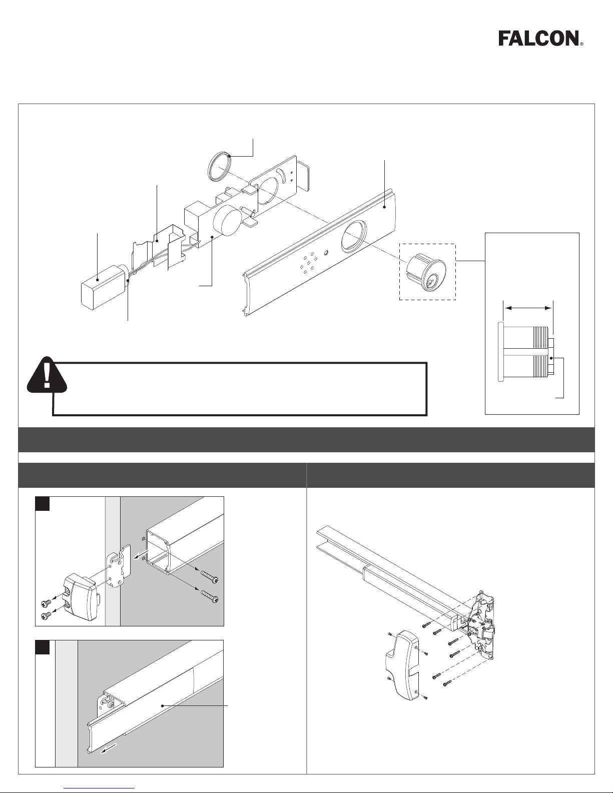
Battery Holder
9 Volt Battery
EA
Installation Instructions24/25 Series Exit Alarm Kit
Cylinder
Nut
Cover Plate
Mortise cylinder
sold separately
Alarm
Hardware
Battery Clip
Important Note
• The Exit Alarm Kit requires a RX or LX switch mounted in the exit device.
1 Remove and discard existing cover plate.
A
d
b
c
1¹⁄₄"
(32 mm)
Standard cam
PREPARE FOR INSTALLATION
2 If exit device has dogging, remove device from door.
If exit device does not have dogging (Fire or less dogging
applications), skip to step 4.
25-R Device
Shown
a
B
Cover Plate
Page 2
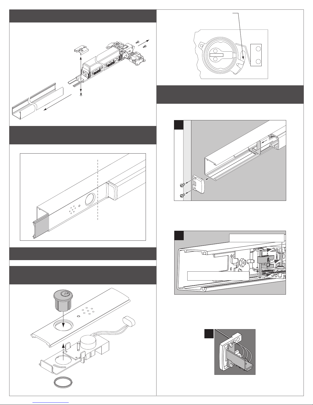
3 Remove and discard dogging assembly.
A
B
C
Dogging assemblies are shown below.
c
Cam should be in
OFF position before
battery is installed
a
b
4 Cut new cover plate as needed to match exit device
length.
Important: Cut end of cover plate nearest the pushbar.
Cover plate should
be flush with end of
mechanism case.
6 If exit device does not have LX or RX switch, install
switch before proceeding.
a. Remove pushbar endcap.
a
b
b. Install the clip and pin.
• Push clip onto the axle linkage pin until it snaps into place.
c
Clip snaps onto top axle.
ASSEMBLE AND INSTALL
5 Assemble the exit alarm unit with the parts in order as
shown below.
Pin slides into bottom slots.
c. Install switch into pushbar endcap.
• Place assembled switch mounting bracket and switch assembly
into the pushbar endcap.
Page 3

d. Reinstall pushbar endcap.
D
L Do not force endcap. If endcap does not t easily, verify
that the switch clip is oriented correctly and the pin is in the
correct slot (step 6b).
a
c
b
7 Attach wiring to terminal blocks on exit alarm kit board
as shown.
L Notes about Wiring:
The EI (external inhibit) option uses NO (normally open) dry contacts
to inhibit the exit alarm.
Closing the access control contacts inhibits the exit alarm. When the
access control contacts are re-opened, the exit alarm re-arms with
no delay.
RX, LX, and EI inputs are not polarized.
EI
Von Duprin 24 VDC
Power Supply
(Polarity Sensitive Input)
NO (normally open)
Access Contol
Contacts
NC
C
NO
8 Reinstall exit device onto door as needed.
9 Slide battery plug through battery holder.
24VDC
Yellow
D
Red
J
Blue
F
Prior to 2012, the RX wires were
*
Red/Yellow/Blue
(use Red and Yellow).
L Install exit alarm assembly in exit device.
EI
Insulate
unused
wire
Gray
Black
Violet
RX Switch
10 Slide battery onto holder.
EPT 10
Make sure
polarity
is correct
RX/LX
Switch
*
Page 4

11 Attach battery and holder into end cap bracket.
EMERGENCY EXIT
PUSH T O OPEN
OPERATING INSTRUCTIONS
12 Install end cap.
Battery
Holder
Tighten two
(2) screws.
1 Insert the key into the cylinder and arm the unit by
turning the key clockwise to position B until it stops.
Return key to position A to remove.
L Note: There is a 15 to 20 second delay before arming during
which the LED will ash every 3 to 5 seconds.
TO ARM
RHR Shown
(LHR opposite)
A
B
2 Observe the LED.
After the 15-20 second delay has passed, the horn will sound briey
and the LED will ash every 12 to 15 seconds. This indicates that
the exit alarm kit is now in armed mode.
13 Install decal on exit device pushbar.
3 Turn the key counterclockwise to position C to disarm.
TO DISARM
C
A
RHR Shown
(LHR opposite)
ALA RM
WILL S OUND
Push to test
Customer Service
1-877-671-7011 www.allegion.com/us
© Allegion 2018
Printed in U.S.A.
23963390 Rev. 05/18-e
XCCE-Q513-050E
 Loading...