

Falcon MEL 24 Series, 25 Series Installation Instructions Manual
*941367-00*
941367-00
MEL 24/25 Series
Motorized Electric Latch Retraction
These instructions are for MEL conversion kits or MEL
devices with preinstalled motors.
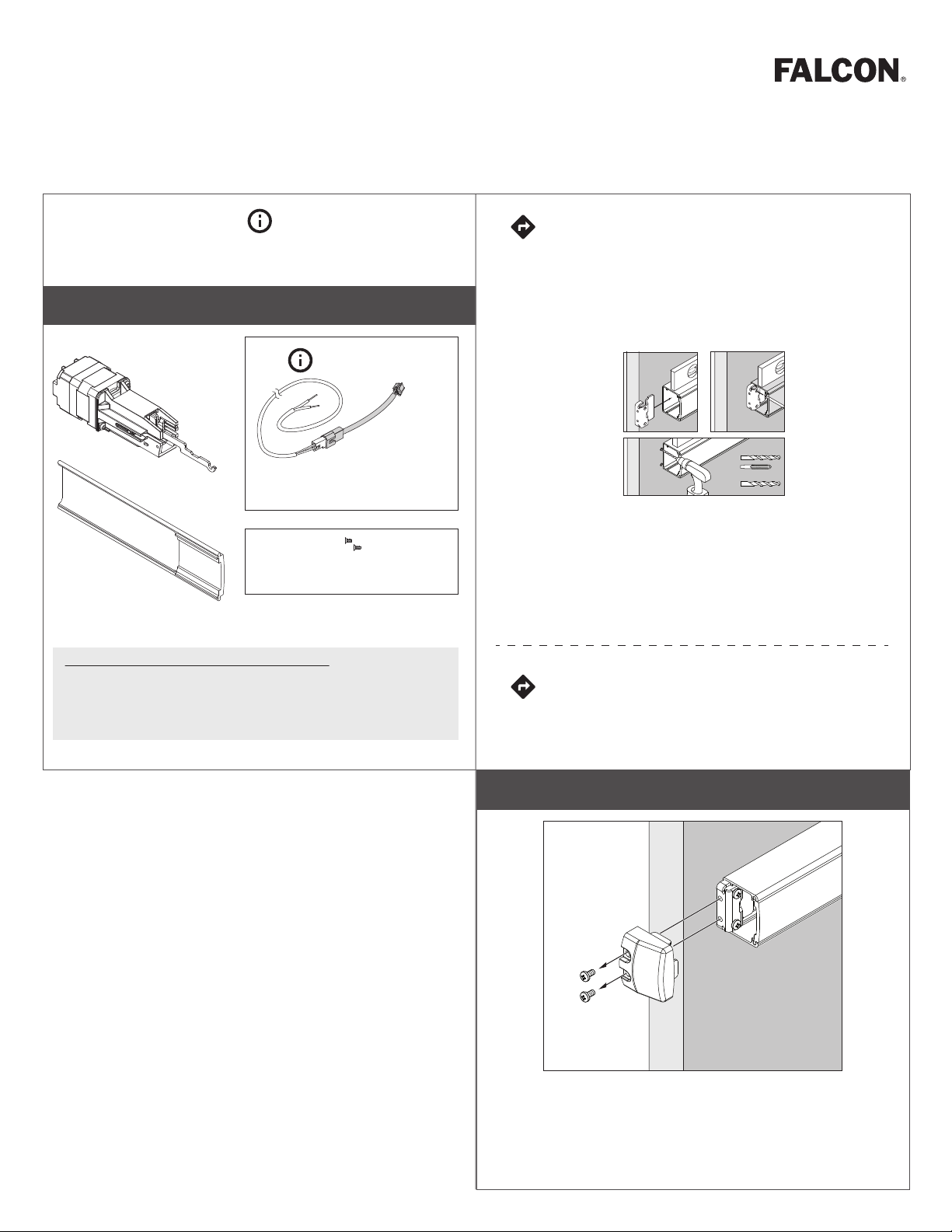
Parts
MEL motor
assembly
MEL 6' cable with motor cable
MEL
cover plate
4-20 x ¹⁄₄" FHP screws (qty 2)
Do not discard
Motor cable
only
(114320)
(47269206)
MEL motor mounting
Installation Instructions
If MEL is preinstalled in the device:
Follow original device instruction up to the point
A.
where this end mounting bracket step has been
completed.
Mark and Prepare 2 Holes
a
c
Complete MEL wiring per steps 15-21 of this
B.
instruction.
Return to original device instruction at point you left
C.
off, and complete installation.
b
Metal/Metal/Métal
#25
#10-24
Wood/Madera/Bois
¹⁄₈" (3 mm) x 1" (25 mm)
Allegion Connect accessories available to order
106198 MEL-CON adapter cable with 8-pin connector
040069 MEL motor cable + MEL-CON adapter cable with 8-pin
connector
If installing the MEL conversion kit, follow
the instruction steps as written.
1 Remove end cap
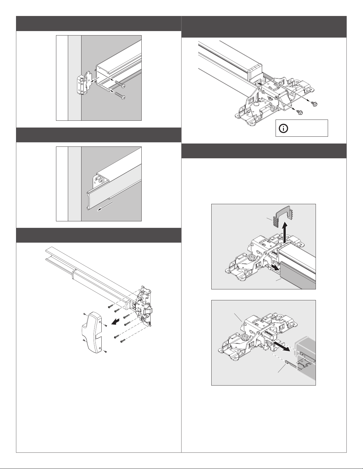
2 Remove device end mounting bracket from door
3 Slide back, remove and discard old cover plate
5 With device laying on a table or bench, remove the 2
screws that connect mechanism case to center case
Use long shank
screwdriver.
6 Unhook baseplate from center case
a. Slide back mechanism case about 2” to access hooking
parts.
b. Push bar guides will come loose and will need to be
reinstalled later.
c. Unhook baseplate from center case.
4 Remove center case cover and device from door
b
a
center
case
pushbar
guide
mechanism
case
baseplate
b
a
c
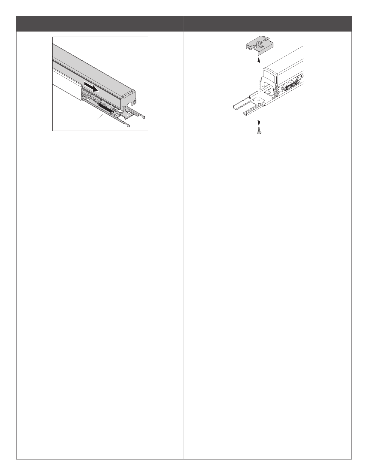
7 Slide baseplate out of mechanism case
baseplate
8 Remove any existing dogging assembly
d.
e.
f. Slide m
32
sticker
Use #1 Phillips
screwdriver
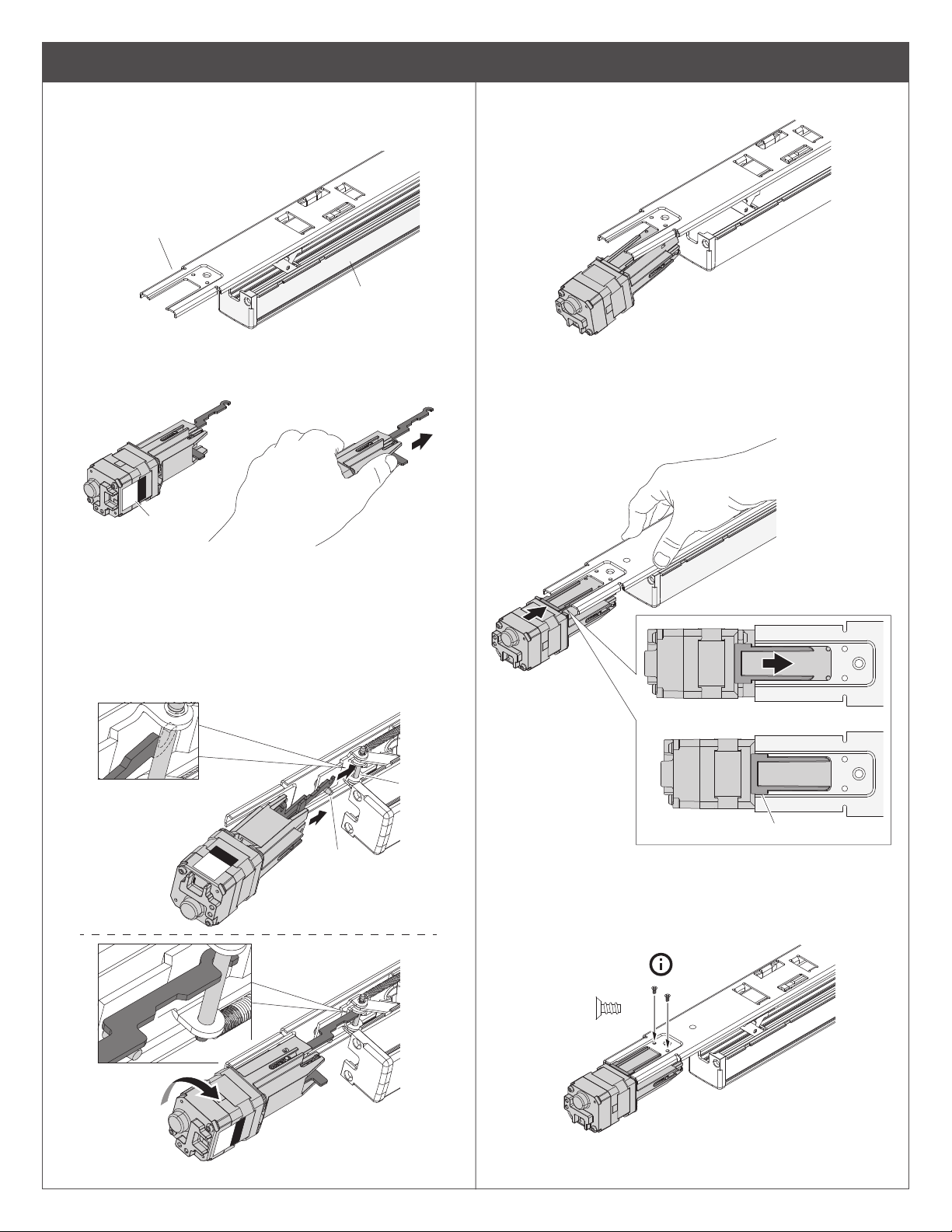
9 Secure motor assembly
a. Turn baseplate assembly upside down so pushpad is
resting on a at surface and motor mounting location is on
the left.
motor mounting
location
pushpad
b. Place motor in left hand with LED status sticker facing
toward you. Gently extend silver hook arm outward (about
Z\x”) until you meet some resistance, then hold.
b
LED
status
d. Set motor on at surface.
e. Push down rmly on baseplate so it bottoms out against
push pad.
f. While depressing baseplate, lift up motor assembly and
guide it along elongated baseplate slot until motor lip slips
over baseplate.
e
c. While tilting baseplate assembly away from you slightly,
move extended hook arm into position under baseplate. A
post will be hanging down from baseplate; the hook arm
should sit on the near side of that post. Rotate the motor
assembly to hook the arm over the baseplate axle pin that
is closest to the baseplate. Do not pull out on motor at this
step.
pin
post
f
Lip slips over baseplate
g. Release baseplate. Secure motor assembly with 2 small
self-tapping screws (provided).
90°
h. Turn baseplate and motor assembly right side up.
 Loading...