

Page 1
User Manual
Falcom TWIST GSM-Modem
Falcom TWIST GSM-Modem
Page 2

© 2001
The information in this manual is copyrighted for Falcom Wireless
Communications GmbH. Any reproduction of this User Manual in whole
or in part, electronic storage or translation in other languages are
permitted only with the prior written consent of Falcom Wireless
Communications GmbH.
The stated data is for the purpose of product description only and shall
not be regarded as guaranteed properties in the legal sense.
All rights reserved.
Trademarks:
Windows is a registered trademark of Microsoft Corporation.
Page 3

User Manual Contents
Contents
List of figures 3
Versions 5
1 Preliminary notes 7
1.1 General . . . . . . . . . . . . . . . . . . . . . . . . . . . . . . . . . . . . . . . . . 7
1.2 Alert symbols used . . . . . . . . . . . . . . . . . . . . . . . . . . . . . . . . 7
1.3 Scope of delivery . . . . . . . . . . . . . . . . . . . . . . . . . . . . . . . . . . 7
2 Technical specifications 8
3 Security 11
4 Safety standards 15
5 Technical description 17
5.1 Parts and brief description . . . . . . . . . . . . . . . . . . . . . . . . . . 17
6 Start-up 21
6.1 Basic installation . . . . . . . . . . . . . . . . . . . . . . . . . . . . . . . . . 21
6.1.1 Display window . . . . . . . . . . . . . . . . . . . . . . . . . . . . . . . 33
7 GSM-Communicator 37
7.1 Installation of the GSM-Communicator . . . . . . . . . . . . . . . . 37
7.1.1 Minimum system requirements . . . . . . . . . . . . . . . . . . . 37
7.1.2 Installation . . . . . . . . . . . . . . . . . . . . . . . . . . . . . . . . . . . 38
TWIST GSM-Modem Version 1.00 Page 1
Page 4

Contents User Manual
7.2 Initialization . . . . . . . . . . . . . . . . . . . . . . . . . . . . . . . . . . . . . 41
7.3 Main menu. . . . . . . . . . . . . . . . . . . . . . . . . . . . . . . . . . . . . . 43
7.3.1 Voice call . . . . . . . . . . . . . . . . . . . . . . . . . . . . . . . . . . . . 45
7.3.2 Phone book . . . . . . . . . . . . . . . . . . . . . . . . . . . . . . . . . . 49
7.3.3 SMS . . . . . . . . . . . . . . . . . . . . . . . . . . . . . . . . . . . . . . . . 51
7.3.4 Internet. . . . . . . . . . . . . . . . . . . . . . . . . . . . . . . . . . . . . . 53
8 Annex 55
8.1 Falcom.ini file. . . . . . . . . . . . . . . . . . . . . . . . . . . . . . . . . . . . 55
8.2 AT-Commands for start-up of the
Falcom TWIST GSM-Modem . . . . . . . . . . . . . . . . . . . . . . . 57
8.2.1 Transfer PIN. . . . . . . . . . . . . . . . . . . . . . . . . . . . . . . . . . 57
8.2.2 Activate saved default parameters. . . . . . . . . . . . . . . . . 58
8.2.3 Change and save defaults . . . . . . . . . . . . . . . . . . . . . . . 58
8.3 AT-Commands for user . . . . . . . . . . . . . . . . . . . . . . . . . . . . 58
8.3.1 Data transfer . . . . . . . . . . . . . . . . . . . . . . . . . . . . . . . . . 58
8.3.2 Setting the SMS Center . . . . . . . . . . . . . . . . . . . . . . . . . 58
8.3.3 Send SMS . . . . . . . . . . . . . . . . . . . . . . . . . . . . . . . . . . . 59
8.3.4 Receive SMS . . . . . . . . . . . . . . . . . . . . . . . . . . . . . . . . . 59
8.3.5 Send voice call. . . . . . . . . . . . . . . . . . . . . . . . . . . . . . . . 60
8.4 General AT-Commands. . . . . . . . . . . . . . . . . . . . . . . . . . . . 61
8.5 Pin configuration of the 9-pole D-sub socket . . . . . . . . . . . . 63
8.6 Pin configuration of serial data cable. . . . . . . . . . . . . . . . . . 64
8.7 Falcom TWIST GSM-Modem troubleshooting
guide . . . . . . . . . . . . . . . . . . . . . . . . . . . . . . . . . . . . . . . . . . 65
8.8 Service. . . . . . . . . . . . . . . . . . . . . . . . . . . . . . . . . . . . . . . . . 67
Page 2 Version 1.00 TWIST GSM-Modem
Page 5

User Manual List of figures
List of figures
Fig. 1: Falcom TWIST GSM-Modem . . . . . . . . . . . . . . . . . . . . . . 17
Fig. 2: Headset . . . . . . . . . . . . . . . . . . . . . . . . . . . . . . . . . . . . . . 18
Fig. 3: Installing the GSM antenna . . . . . . . . . . . . . . . . . . . . . . . 21
Fig. 4: Connecting the data cable to the computer . . . . . . . . . . . 22
Fig. 5: Connecting the data cable to the modem. . . . . . . . . . . . . 22
Fig. 6: Loading the SIM card step 1 . . . . . . . . . . . . . . . . . . . . . . 23
Fig. 7: Loading the SIM card step 2 . . . . . . . . . . . . . . . . . . . . . . 23
Fig. 8: Loading the SIM card step 3 . . . . . . . . . . . . . . . . . . . . . . 24
Fig. 9: Connecting the modem to the power supply . . . . . . . . . . 25
Fig. 10: Power supply with AC/DC adapter. . . . . . . . . . . . . . . . . . 25
Fig. 11: Connecting the headset . . . . . . . . . . . . . . . . . . . . . . . . . . 26
Fig. 12: Driver/driver application step 1. . . . . . . . . . . . . . . . . . . . . 26
Fig. 13: Driver/driver application step 2. . . . . . . . . . . . . . . . . . . . . 27
Fig. 14: Driver/driver application step 3. . . . . . . . . . . . . . . . . . . . . 27
Fig. 15: Windows modem installation step 1. . . . . . . . . . . . . . . . . 28
Fig. 16: Windows modem installation step 2. . . . . . . . . . . . . . . . . 28
Fig. 17: Windows modem installation step 3. . . . . . . . . . . . . . . . . 29
Fig. 18: Windows modem installation step 4. . . . . . . . . . . . . . . . . 29
Fig. 19: Windows modem installation step 5. . . . . . . . . . . . . . . . . 30
Fig. 20: Driver/driver application completion window . . . . . . . . . . 31
Fig. 21: Task bar with icon . . . . . . . . . . . . . . . . . . . . . . . . . . . . . . 31
Fig. 22: The Enter PIN window . . . . . . . . . . . . . . . . . . . . . . . . . . . 32
Fig. 23: Display window. . . . . . . . . . . . . . . . . . . . . . . . . . . . . . . . . 33
Fig. 24: File menu item . . . . . . . . . . . . . . . . . . . . . . . . . . . . . . . . . 33
Fig. 25: PIN menu item . . . . . . . . . . . . . . . . . . . . . . . . . . . . . . . . . 34
Fig. 26: Configuration menu item . . . . . . . . . . . . . . . . . . . . . . . . . 34
Fig. 27: SMS Settings . . . . . . . . . . . . . . . . . . . . . . . . . . . . . . . . . . 35
Fig. 28: Options. . . . . . . . . . . . . . . . . . . . . . . . . . . . . . . . . . . . . . . 35
Fig. 29: Reinitialization 1 . . . . . . . . . . . . . . . . . . . . . . . . . . . . . . . . 36
Fig. 30: Reinitialization 2 . . . . . . . . . . . . . . . . . . . . . . . . . . . . . . . . 36
Fig. 31: Info menu item . . . . . . . . . . . . . . . . . . . . . . . . . . . . . . . . . 36
Fig. 32: GSM-Communicator step 1 . . . . . . . . . . . . . . . . . . . . . . . 38
Fig. 33: GSM-Communicator step 2 . . . . . . . . . . . . . . . . . . . . . . . 39
TWIST GSM-Modem Version 1.00 Page 3
Page 6

List of figures User Manual
Fig. 34: GSM-Communicator Disk Space . . . . . . . . . . . . . . . . . . . 39
Fig. 35: GSM-Communicator step 3 . . . . . . . . . . . . . . . . . . . . . . . 40
Fig. 36: GSM-Communicator step 4 . . . . . . . . . . . . . . . . . . . . . . . 40
Fig. 37: Prompt window. . . . . . . . . . . . . . . . . . . . . . . . . . . . . . . . . 41
Fig. 38: configure Port window . . . . . . . . . . . . . . . . . . . . . . . . . . . 42
Fig. 39: configure internet window. . . . . . . . . . . . . . . . . . . . . . . . . 42
Fig. 40: Main menu window. . . . . . . . . . . . . . . . . . . . . . . . . . . . . . 43
Fig. 41: Main menu without SIM card . . . . . . . . . . . . . . . . . . . . . . 44
Fig. 42: Headset prompt . . . . . . . . . . . . . . . . . . . . . . . . . . . . . . . . 45
Fig. 43: Voice call window. . . . . . . . . . . . . . . . . . . . . . . . . . . . . . . 45
Fig. 44: Call history . . . . . . . . . . . . . . . . . . . . . . . . . . . . . . . . . . . . 46
Fig. 45: Select from call history . . . . . . . . . . . . . . . . . . . . . . . . . . . 48
Fig. 46: DTMF Dialer window . . . . . . . . . . . . . . . . . . . . . . . . . . . . 48
Fig. 47: Incoming call . . . . . . . . . . . . . . . . . . . . . . . . . . . . . . . . . . 49
Fig. 48: Phone book . . . . . . . . . . . . . . . . . . . . . . . . . . . . . . . . . . . 50
Fig. 49: SMS window. . . . . . . . . . . . . . . . . . . . . . . . . . . . . . . . . . . 51
Fig. 50: incoming SMS field. . . . . . . . . . . . . . . . . . . . . . . . . . . . . . 52
Fig. 51: Internet start address window . . . . . . . . . . . . . . . . . . . . . 53
Page 4 Version 1.00 TWIST GSM-Modem
Page 7
User Manual Versions
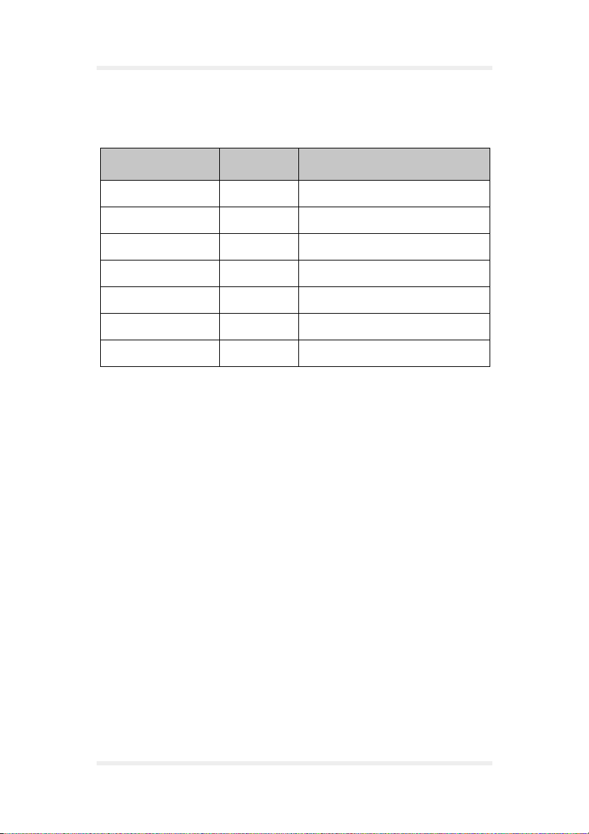
Versions
Version number Author Changes
1.00 J. Skeide Initial version
TWIST GSM-Modem Version 1.00 Page 5
Page 8

Versions User Manual
Page 6 Version 1.00 TWIST GSM-Modem
Page 9
User Manual Preliminary notes
1 Preliminary notes
1.1 General
Thank you very much for deciding to buy the Falcom TWIST
GSM-Modem.
This User Manual contains all information you require to use the
Falcom TWIST GSM-Modem.
Please read this User Manual very carefully to avoid mistakes and to
make optimal use of the modem.
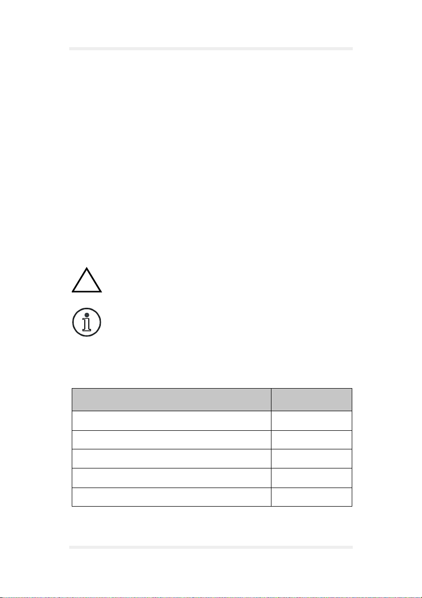
1.2 Alert symbols used
Alerts the user to potential safety risks or damage of the
!
application software
Indicates important information and tips
1.3 Scope of delivery
Part Quantity
Basic unit 1
Antenna 1
Serial data cable 1
Mains cable with AC/DC adapter 1
Setup CD 1
TWIST GSM-Modem Version 1.00 Page 7
Page 10
Technical specifications User Manual
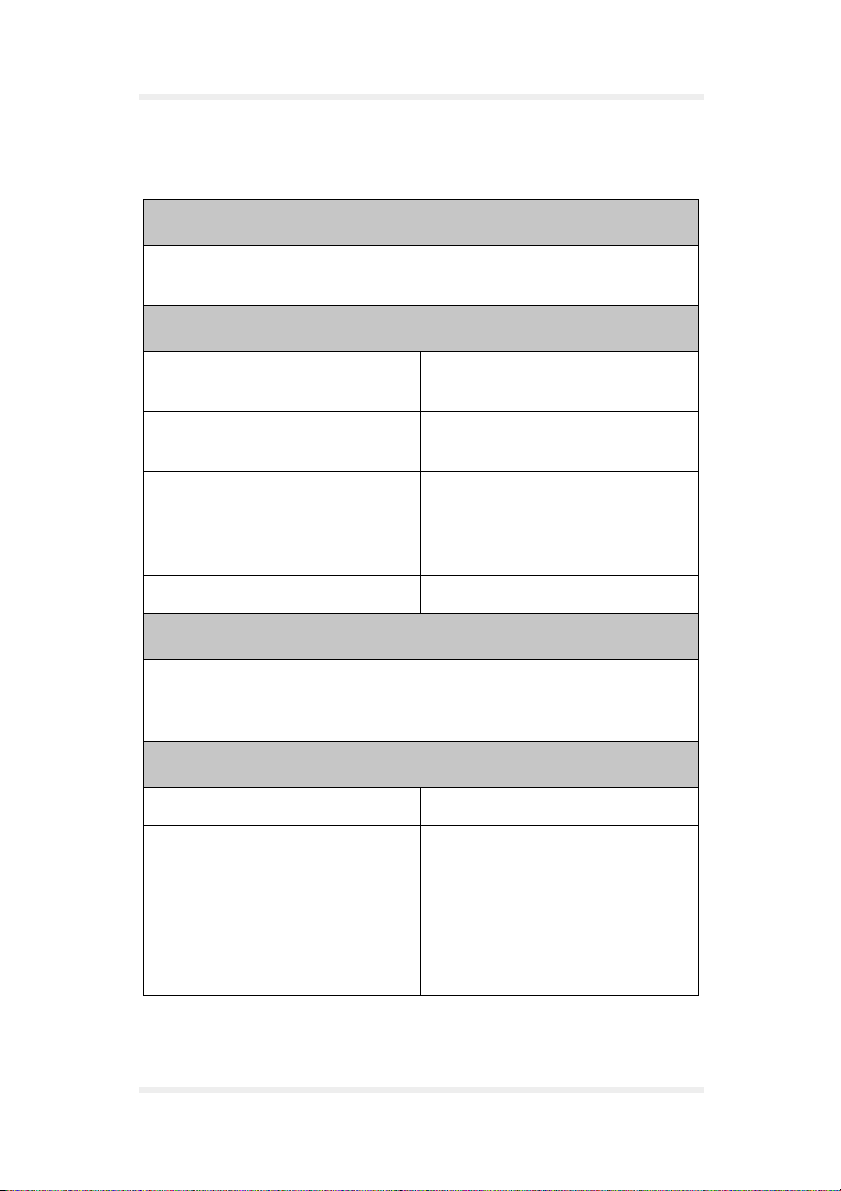
2 Technical specifications
Communications standard
GSM 900/1800 (1900) Phase 2/2+
Dual Band Modem
GSM services
Telephony Emergency Calls
FR/ERF/HR DTMF
SMS MO, MT, Cell Broadcast
Return Call Message
Data 300 ... 14400BPS, transparent/
non-transparent, V.21, V.22,
V.23, V. 2 2 b i s V. 26 t er, V.3 2 ,
V.34, V. 11 0
Fax Group3 / Class 2
Supplementary services
Echo Cancellation, Call Forwarding, Phonebook, Multiparty, Call
Baring, Fixed Dialling Number, Call waiting and Call hold, Call Line
Identity, Advice of Charge, USSD
Electrical parameters
Power supply DC 5 V +/- 20 %
Current consumption GSM 900:
• 120 mA/5 V Power Mode 1
(idle)
• 570 mA/5 V Power Mode 2
(Power Level 5; max.)
• 500 mA/5 V Power Mode 3
(Power Level 7)
Page 8 Version 1.00 TWIST GSM-Modem
Page 11

User Manual Technical specifications
Electrical parameters
Current consumption GSM 1800:
• 120 mA/5 V Power Mode 1
(idle)
• 400 mA/5 V Power Mode 2
(Power Level 3; max.)
• 340 mA/5 V Power Mode 3
(Power Level 7)
Sensitivity GSM 900: <-104 dBm
GSM 1800: <-100 dBm
Interfaces
D-Sub 9pin (female) RS 232
RJ45 8pin (shielded) Audio (headset / handset)
Power output, Control signals
Power input AC/DC adapter
(FRIWO type 7238/05)
Falcom dual-band antenna or SMB-Connector for other GSM
antenna
SIM card reader small SIM card
Ambient temperature
Mains supply -20 °C bis +55 °C
Storage temperature -20 °C bis +70 °C
General specifications
Dimensions (L x W x H) • 114 x 52 x 27 (without
antenna)
• 118 x 52 x 56 (with Falcom
dual-band antenna)
Weight 92 g
TWIST GSM-Modem Version 1.00 Page 9
Page 12

Technical specifications User Manual
Accessories
GSM 900/1800 (1900) antenna
dual-band antenna with SMB plug connector
Serial data cable (0,5 m with D-sub 9 plug connector, see
chapter 8.6)
Mains supply cable with AC/DC adapter (type FRIWO FW 7238/05)
Setup CD for Windows 95/98/CE and Windows 2000 with current
driver and driver application as well as GSM-Communicator
application software
Headset (optional) with RJ45 8pin audio plug connector
Modem registrations
GSM ETSI Phase 1 und 2
CE label acc. CE 168X
Page 10 Version 1.00 TWIST GSM-Modem
Page 13

User Manual Security
3 Security
IMPORTANT FOR THE EFFICIENT AND SAFE OPERATION OF
YOUR GSM MODEM READ THIS INFORMATION BEFORE USE !
Your GSM modem is one of the most exciting and innovative electronic
products ever developed. With it you can stay in contact with your
office, your home, emergency services, and others, wherever service
is provided.
GENERAL
Your modem utilises the GSM standard for cellular technology. GSM is
a newer radio frequency («RF») technology than the current FM
technology that has been used for radio communications for decades.
The GSM standard has been established for use in the European
community and elsewhere.
Your modem is actually a low power radio transmitter and receiver. It
sends out and receives radio frequency energy. When you use your
modem, the cellular system handling your calls controls both the radio
frequency and the power level of your cellular modem.
EXPOSURE TO RF ENERGY
There has been some public concern about possible health effects of
using GSM modem. Although research on health effects from RF
energy has focused for many years on the current RF technology,
scientists have begun research regarding newer radio technologies,
such as GSM. After existing research had been reviewed, and after
compliance to all applicable safety standards had been tested, it has
been concluded that the product is fit for use.
If you are concerned about exposure to RF energy there are things you
can do to minimise exposure. Obviously, limiting the duration of your
calls will reduce your exposure to RF energy. In addition, you can
reduce RF exposure by operating your cellular modem efficiently by
following the below guidelines.
TWIST GSM-Modem Version 1.00 Page 11
Page 14

Security User Manual
EFFICIENT MODEM OPERATION
For your modem to operate at the lowest power level, consistent with
satisfactory call quality:
If your modem has an extendible antenna, extend it fully. Some models
allow you to place a call with the antenna retracted. However your
modem operates more efficiently with the antenna fully extended.
Do not hold the antenna when the modem is «IN USE». Holding the
antenna affects call quality and may cause the modem to operate at a
higher power level than needed.
ANTENNA CARE AND REPLACEMENT
Do not use the modem with a damaged antenna. If a damaged antenna
comes into contact with the skin, a minor burn may result. Replace a
damaged antenna immediately. Consult your manual to see if you may
change the antenna yourself. If so, use only a manufacturer-approved
antenna. Otherwise, have your antenna repaired by a qualified
technician.
Use only the supplied or approved antenna. Unauthorised antennas,
modifications or attachments could damage the modem and may
contravene local RF emission regulations or invalidate type approval.
DRIVING
Check the laws and regulations on the use of cellular devices in the
area where you drive. Always obey them. Also, when using your
modem while driving, please: give full attention to driving, pull off the
road and park before making or answering a call if driving conditions so
allow. When applications are prepared for mobile use they should fulfil
road-safety instructions of the current law!
ELECTRONIC DEVICES
Most electronic equipment, for example in hospitals and motor vehicles
is shielded from RF energy. However RF energy may affect some
malfunctioning or improperly shielded electronic equipment.
Page 12 Version 1.00 TWIST GSM-Modem
Page 15

User Manual Security
VEHICLE ELECTRONIC EQUIPMENT
Check your vehicle manufacturer’s representative to determine if any
on board electronic equipment is adequately shielded from RF energy.
MEDICAL ELECTRONIC EQUIPMENT
Consult the manufacturer of any personal medical devices (such as
pacemakers, hearing aids, etc...) to determine if they are adequately
shielded from external RF energy.
Turn your modem OFF in health care facilities when any regulations
posted in the area instruct you to do so. Hospitals or health care
facilities may be using RF monitoring equipment.
AIRCRAFT
Turn your modem OFF before boarding any aircraft.
Use it on the ground only with crew permission.
Do not use in the air.
To prevent possible interference with aircraft systems, Federal Aviation
Administration (FAA) regulations require you to have permission from
a crew member to use your modem while the plane is on the ground.
To prevent interference with cellular systems, local RF regulations
prohibit using your modem whilst airborne.
CHILDREN
Do not allow children to play with your modem. It is not a toy. Children
could hurt themselves or others (by poking themselves or others in the
eye with the antenna, for example). Children could damage the
modem, or make calls that increase your modem bills.
TWIST GSM-Modem Version 1.00 Page 13
Page 16

Security User Manual
BLASTING AREAS
To avoid interfering with blasting operations, turn your unit OFF when
in a «blasting area» or in areas posted: «turn off two-way radio».
Construction crew often use remote control RF devices to set off
explosives.
POTENTIALLY EXPLOSIVE ATMOSPHERES
Turn your modem OFF when in any area with a potentially explosive
atmosphere. It is rare, but your modem or its accessories could
generate sparks. Sparks in such areas could cause an explosion or fire
resulting in bodily injury or even death and damages to property.
Areas with a potentially explosive atmosphere are often, but not
always, clearly marked. They include fuelling areas such as petrol
stations; below decks on boats; fuel or chemical transfer or storage
facilities; and areas where the air contains chemicals or particles, such
as grain, dust, or metal powders.
Do not transport or store flammable gas, liquid, or explosives, in the
compartment of your vehicle which contains your modem or
accessories.
Before using your modem in a vehicle powered by liquefied petroleum
gas (such as propane or butane) ensure that the vehicle complies with
the relevant fire and safety regulations of the country in which the
vehicle is to be used.
NON-IONISING RADIATION
As with other mobile radio transmitting equipment, users are advised
that for satisfactory operation and for the safety of personnel, it is
recommended that no part of the human body be allowed to come too
close to the antenna during operation of the equipment.
The radio equipment shall be connected to the antenna via a
non-radiating 50 Ω coaxial cable.
The antenna shall be mounted in such a position that no part of the
human body will normally rest close to any part of the antenna. It is also
recommended to use the equipment not close to medical devices as for
example hearing aids and pacemakers.
Page 14 Version 1.00 TWIST GSM-Modem
Page 17

User Manual Safety standards
4 Safety standards
THIS CELLULAR MODEM COMPLIES WITH ALL APPLICABLE RF
SAFETY STANDARDS.
This cellular modem meets the standards and recommendations for
the protection of public exposure to RF electromagnetic energy
established by governmental bodies and other qualified organisations,
such as the following:
Directives of the European Community, Directorate General V in
Matters of Radio Frequency Electromagnetic Energy.
TWIST GSM-Modem Version 1.00 Page 15
Page 18

Safety standards User Manual
Page 16 Version 1.00 TWIST GSM-Modem
Page 19
User Manual Technical description
5 Technical description
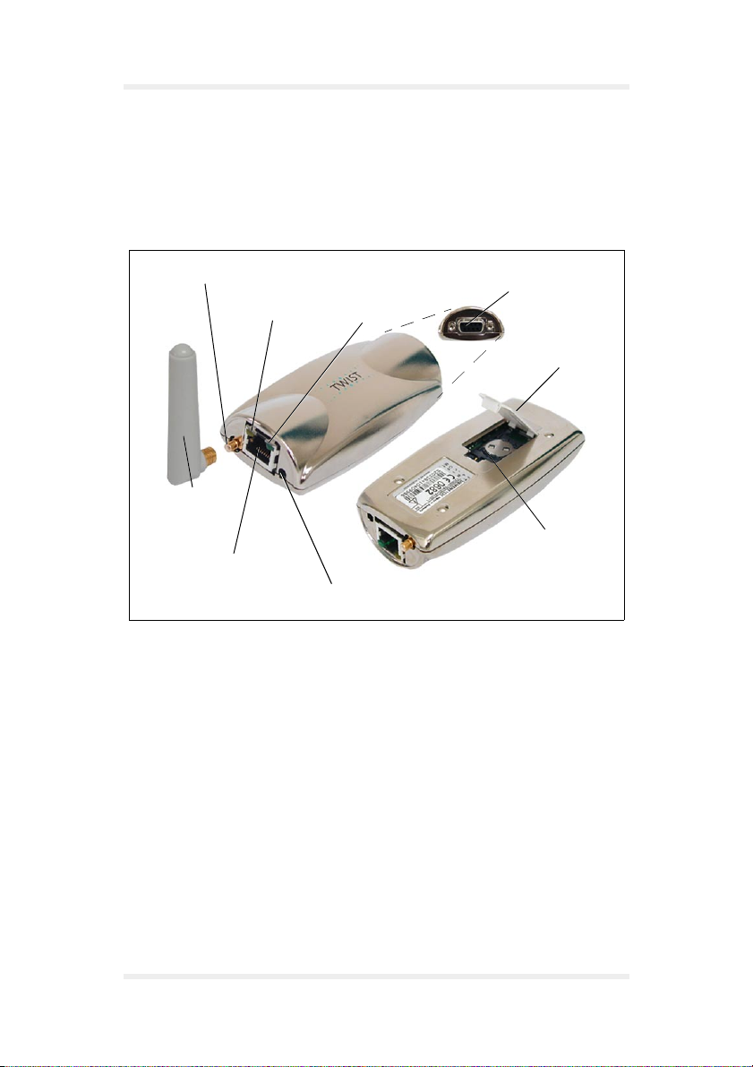
5.1 Parts and brief description
Antenna Socket
SMB
Orange LED
GSM-Antenna
Headset Socket
Fig. 1: Falcom TWIST GSM-Modem
With the Falcom TWIST GSM-Modem, connections can be made to the
GSM 900/1800 (1900) mobile radio network via the computer and the
supplied GSM-Communicator.
After connecting the modem, the following telecommunication services
are available:
Green LED
Power Supply
Serial Port
Cover Cap
SIM-Card Reader
making and receiving voice calls
❐
sending and receiving short messages
❐
data connections V32 (protocol)
❐
class 1/2 fax connections
❐
TWIST GSM-Modem Version 1.00 Page 17
Page 20
Technical description User Manual
All technical components required to establish the above
communication links are integrated in the Falcom TWIST
GSM-Modem.
The serial port is connected to the computer by the data cable.
Power is supplied to the modem from the power supply socket.
The internal SIM card reader serves for holding the SIM card given to
you by your provider, and it is closed by a cover cap.
To make telephone calls you require suitable application software or
you can use the application software contained in the
GSM-Communicator.
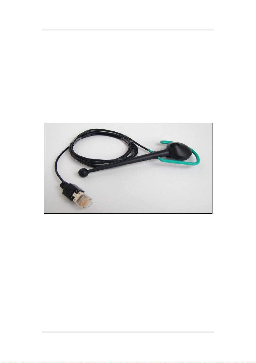
Plug the headset (optional) in the headset socket.
Fig. 2: Headset
Page 18 Version 1.00 TWIST GSM-Modem
Page 21
User Manual Technical description
The orange LED indicator lights up after the modem has been
connected to the power supply. The modem is not registered in the
mobile radio network of the network operator.
The green LED indicator on the modem flashes for 5 seconds after the
PIN number has been entered, and then switches itself off.
The green LED indicator flashes while a data or speech link is being
made, and lights continuously when the receiver answers. The green
LED indicator switches off after the connection has been terminated.
To use data and fax transmission, suitable software must
be installed in the computer (e. g. Microsoft Fax or
similar).
A suitable antenna is the dual-band antenna supplied
with the modem or a separate dual-band antenna with
SMB plug which can be connected to the antenna
socket.
When using the audio accessory, we recommend using
a remote GSM aerial to prevent interference radiation.
TWIST GSM-Modem Version 1.00 Page 19
Page 22

Technical description User Manual
Page 20 Version 1.00 TWIST GSM-Modem
Page 23

User Manual Start-up
6 Start-up
6.1 Basic installation
Install the modem as follows:
1. Exit Microsoft Windows 9x or Windows 2000 and switch off the
computer.
2. Insert the GSM antenna in the SMB socket of the modem.
Fig. 3: Installing the GSM antenna
3. Connect the data cable to the 9-pole COM1 or COM2 port
(depending on which COM is available) of the computer and
tighten the screws hand-tight with a screwdriver (see Fig. 4).
Connect the other end of the data cable to the serial port of the
modem and tighten the screws hand-tight with a screwdriver (see
Fig. 5).
TWIST GSM-Modem Version 1.00 Page 21
Page 24

Start-up User Manual
2
M
O
C
1
M
O
C
Fig. 4: Connecting the data cable to the computer
Fig. 5: Connecting the data cable to the modem
Page 22 Version 1.00 TWIST GSM-Modem
Page 25

User Manual Start-up
4. Open the cover cap on the underside of the modem.
Fig. 6: Loading the SIM card step 1
5. Turn the securing plate as far as it will go with the aid of the cover
cap.
Fig. 7: Loading the SIM card step 2
TWIST GSM-Modem Version 1.00 Page 23
Page 26

Start-up User Manual
6. Flap the holder upwards.
Slide the SIM card into the SIM card holder with the contact
surface facing down and the flattened side at the top left.
Fig. 8: Loading the SIM card step 3
7. Press the holder down and secure it with the securing plate.
Close the opening with the cover cap.
8. The SIM card is removed as follows:
Open the cover cap on the underside of the modem (see Fig. 6).
❐
Turn the securing plate as far as it will go with the aid of the cover
❐
cap (see Fig. 7).
Flap the holder up and pull the SIM card out.
❐
Close the opening with the cover cap.
❐
The SIM card must be inserted before connecting the
!
Page 24 Version 1.00 TWIST GSM-Modem
modem to the power supply, and must not be removed
until after the power supply to the modem has been
deactivated!
Page 27

User Manual Start-up
9. Attach the power cable to the modem.
Fig. 9: Connecting the modem to the power supply
10. Provide the power supply via the AC/DC adapter (type FRIWO FW
7238/05).
Fig. 10: Power supply with AC/DC adapter
TWIST GSM-Modem Version 1.00 Page 25
Page 28

Start-up User Manual
11. Insert the headset (optional) with the RJ45 8pin audio plug
connector in the headset socket of the modem.
Fig. 11: Connecting the headset
12. Install the driver and the driver application for the modem:
Load the installation CD in the CD drive.
❐
Double-click the setup.exe file in the A2D-Driver102 folder.
❐
Click [Next].
❐
Fig. 12: Driver/driver application step 1
Page 26 Version 1.00 TWIST GSM-Modem
Page 29

User Manual Start-up
Select Browse... to define the required program path.
❐
Then click [Next].
Fig. 13: Driver/driver application step 2
Then click [Next].
❐
Fig. 14: Driver/driver application step 3
TWIST GSM-Modem Version 1.00 Page 27
Page 30

Start-up User Manual
Click [Next].
❐
Fig. 15: Windows modem installation step 1
Windows starts the automatic modem identification.
❐
Fig. 16: Windows modem installation step 2
Page 28 Version 1.00 TWIST GSM-Modem
Page 31

User Manual Start-up
Click [Next].
❐
You can change the type of the installed modem with
[Change].
Fig. 17: Windows modem installation step 3
Click [Finish].
❐
Fig. 18: Windows modem installation step 4
TWIST GSM-Modem Version 1.00 Page 29
Page 32

Start-up User Manual
Click [OK].
❐
If you want to change the modem properties, use the buttons in
the displayed dialog screen.
Fig. 19: Windows modem installation step 5
Page 30 Version 1.00 TWIST GSM-Modem
Page 33

User Manual Start-up
Click [Finish].
❐
Fig. 20: Driver/driver application completion window
When the driver and the driver application have been successfully
installed, an icon is displayed on the task bar (see Fig. 21) and a
window prompts you to enter the personal identification number (PIN)
opens (see Fig. 22).
The PIN is a security number (mostly comprising four
digits), which protects the SIM from unauthorized use.
Fig. 21: Task bar with icon
TWIST GSM-Modem Version 1.00 Page 31
Page 34

Start-up User Manual
Fig. 22: The Enter PIN window
Save PIN Saves the PIN in the system.
Saving the PIN is a safety feature to protect the
!
The green LED indicator on the modem flashes for 5 seconds after the
PIN number has been entered, and then switches itself off.
computer from use by an unauthorized person.
If a wrong PIN is entered 3 times in succession, the SIM
card will be deactivated.
When this happens, the SIM card can only be released
with the PUK (super PIN) number supplied by the
provider.
Mouse-click the task bar icon to open the display window with
information about the status of the modems (see Fig. 23).
Page 32 Version 1.00 TWIST GSM-Modem
Page 35

User Manual Start-up
6.1.1 Display window
The display window menu contains the following functions:
Fig. 23: Display window
6.1.1.1 File menu item
The File menu items contains the close function.
Fig. 24: File menu item
The close function closes the display window and pits it in the task bar.
TWIST GSM-Modem Version 1.00 Page 33
Page 36

Start-up User Manual
6.1.1.2 PIN menu item
The PIN menu item contains the functions Enter PIN and Delete PIN.
Fig. 25: PIN menu item
The function Enter PIN prompts the user to enter his personal
identification number and confirm the entry.
The function Delete PIN deletes the PIN in the registration of Microsoft
Windows. After the PIN is deleted, it can be entered again with every
new start of the application.
The Delete PIN function is only active when Save PIN
has been selected in the PIN prompt window (see
Fig. 22).
6.1.1.3 Configuration menu item
The Configuration menu item provides the functions SMS Settings,
Options and Reinitialization.
Fig. 26: Configuration menu item
Page 34 Version 1.00 TWIST GSM-Modem
Page 37

User Manual Start-up
The number displayed in the SMS Settings function window is the
telephone number of the SMS Service Center of your network provider.
This number is permanently stored on the SIM card.
Fig. 27: SMS Settings
In the Options function window (see Fig. 28) the modem check
function is set in the field Check modem status. The status can be
checked for:
the mobile network in which the user has logged in
❐
whether the user has logged in
❐
the field strength of the mobile network
❐
The time of inactivity after which the modem is switched off is set in the
Turn off modem automatically if it is not used field in the Options
window (see Fig. 28).
Fig. 28: Options
TWIST GSM-Modem Version 1.00 Page 35
Page 38

Start-up User Manual
With the Reinitialization item in the Configuration menu, the
initialization of the modem is repeated.
All default settings of the modem are restored. Press Ja to continue or
Nein to quit this option (see Fig. 29).
Fig. 29: Reinitialization 1
If you press Ja a window opens in which the successful reinitialization
of the modem is confirmed (see Fig. 30).
Fig. 30: Reinitialization 2
6.1.1.4 Info menu item
The Info menu item contains the About function.
Fig. 31: Info menu item
Clicking About displays information on the supplier and the version of
the driver application.
Page 36 Version 1.00 TWIST GSM-Modem
Page 39

User Manual GSM-Communicator
7 GSM-Communicator
All important user functions of the user software of the modem can be
accessed from the control surface.
The following telecommunication functions are provided by the user
software:
making and receiving calls
❐
sending and receiving short messages
❐
The program parameters can be customized in the Falcom.ini file (see
chapter 8.1).
The structure of the Falcom.ini file must not be changed!
!
The Falcom.ini file is the most important initialization file
of the GSM-Communicator user software. The file is
generated automatically in the path defined by you at the
first program start and contains the default settings for
the program.
If a fault occurs in the Falcom.ini file, it can be deleted
and is generated again when the program is started next.
7.1 Installation of the GSM-Communicator
7.1.1 Minimum system requirements
Pentium 133 - 64 MB RAM
❐
Microsoft Windows 9x, Windows 2000
❐
1 unused serial port
❐
Before installing the software, please check if your computer has the
necessary requirements.
TWIST GSM-Modem Version 1.00 Page 37
Page 40

GSM-Communicator User Manual
7.1.2 Installation
Load the installation CD in the CD drive of your computer.
❐
Double-click setup.exe in the GSM-Communicator 305 folder.
❐
Click [Next].
❐
Fig. 32: GSM-Communicator step 1
Click [Next] again.
❐
Define the program path in the Folder field.
With Browse... you can select the installation path you require in
the Folder field.
You can interrupt the installation with a click on Cancel and go
back one step with a click on Previous (see Fig. 33).
Page 38 Version 1.00 TWIST GSM-Modem
Page 41

User Manual GSM-Communicator
Fig. 33: GSM-Communicator step 2
With a click on Disk Cost... (see Fig. 33) the system checks if
❐
sufficient free memory is available on the drives (see Fig. 34).
Fig. 34: GSM-Communicator Disk Space
Now click [Next].
❐
TWIST GSM-Modem Version 1.00 Page 39
Page 42

GSM-Communicator User Manual
Fig. 35: GSM-Communicator step 3
Now click [Close].
❐
Fig. 36: GSM-Communicator step 4
Page 40 Version 1.00 TWIST GSM-Modem
Page 43

User Manual GSM-Communicator
When the installation is complete, the program can be run from
❐
the start menu or the link to the desktop can be enabled.
If the system files require updating, you are prompted to
start the computer again.
After starting the computer, click Setup.exe for a new
installation.
After successful installation the program can be run from
the start menu or the link to the desktop can be enabled.
7.2 Initialization
When the program starts a prompt window is displayed asking you to
check the SIM card and all connectors (see Fig. 37).
The SIM card must be located in the SIM card reader and
the modem must be connected to the power supply.
Fig. 37: Prompt window
TWIST GSM-Modem Version 1.00 Page 41
Page 44

GSM-Communicator User Manual
Mouse-click the OK button in the prompt window (see Fig. 37) to
open the configure Port window (see Fig. 38). This window is only
displayed on the first start of the GSM-Communicator user software or
when the Falcom.ini file is generated.
Enter the COM port to which you want to connect the modem to the
computer in the configure Port window.
Confirm the selected COM port with OK.
Fig. 38: configure Port window
The configure internet window then appears (see Fig. 39). The
appropriate Internet start address must be entered in this window. This
entry is confirmed with the OK button.
The configure internet window is only opened the first time the GSM-
Communicator user software is started.
Fig. 39: configure internet window
If the connection is not made for more than 15 seconds,
the program quits after displaying a fault message.
Page 42 Version 1.00 TWIST GSM-Modem
Page 45

User Manual GSM-Communicator
7.3 Main menu
The main menu contains all modem functions for which icons are
provided (see Fig. 40).
Fig. 40: Main menu window
Provider Name of the mobile network
Signal Mobile signal strength in dbm
Voice call Menu for making voice call
SMS Menu for short messages
Internet Connections to the internet
User guide Provides information for the user
Emergency call Dials the emergency number
Exit Closes a window
Refresh all Reinitializes the modems with PIN
prompt and checks of field strength,
registration in the mobile radio network
and the mobile radio network provider
TWIST GSM-Modem Version 1.00 Page 43
Page 46

GSM-Communicator User Manual
minimize Minimizes the window and places it on
the taskbar
The signal field strength is displayed when the mouse
pointer is located over the icon in the task bar.
serial link
Green
Blinking red
COM1: 9600,n,8,1 COM1 serial port
After a one-time log-in the Emergency call button is
enabled when the program is started without the SIM
card.
Indicates the connection status of the
modem with the computer
Connected to the serial data cable
Connection to the computer is interrupted,
program displays an error message and is
canceled after 5 seconds
9600, n, 8, 1 Parameter anchored in the
communication protocol of
the GSM modem
Fig. 41: Main menu without SIM card
Page 44 Version 1.00 TWIST GSM-Modem
Page 47

User Manual GSM-Communicator
The emergency call number (default 112) can be
changed in the Falcom.ini file (see chapter 8.1).
7.3.1 Voice call
The Voice call button (see Fig. 40) accesses the functions for making
and receiving calls.
When the function Voice call is enabled for the first time, the system
inquires of a headset (optional) is connected.
Fig. 42: Headset prompt
Then the voice call control surface is displayed.
Fig. 43: Voice call window
TWIST GSM-Modem Version 1.00 Page 45
Page 48

GSM-Communicator User Manual
Makes a new entry in the SIM card phone
book
Deletes the selected entry from the SIM
card phone book
Changes selected entry in the SIM card
phonebook.
Finds an entry in the SIM card
phonebook.
Stops editing the phone book entry
call number name Field displays the position, call number
and the name of the entry on the SIM
card
call number Field displays the call number or
shortcode in the SIM card phone book
name Field displays the name related to the call
number
call Makes the telephone connection (all
dialed numbers are stored in the call
history)
clear call history Deletes all numbers from the call history
Fig. 44: call history
Page 46 Version 1.00 TWIST GSM-Modem
Page 49

User Manual GSM-Communicator
answer Receives an incoming call
hang up Ends a call, Button becomes active when
a telephone connection has been made.
Extension dialing Activates or deactivates the DTMF tone
dialing during a voice connection
Ringer melody
(is not available for the
Falcom TWIST)
set melody
(is not available for the
Falcom TWIST)
Signal Signal strength of the mobile phone in
change level
(is not available for the
Falcom TWIST)
to main Returns to the main menu
The call number field always displays the last dialed number (see
Fig. 43).
The SIM card phone book entries can be viewed with a click on call
number name (see Fig. 43).
A number is dialed by direct input in the call number field or from the
displayed phone list.
Double-clicking the selected number enters the call number field as
well as name field automatically with the entry from the phone book.
Selects one of 10 different ringer
melodies (value 0 in the Falcom.ini file
deactivates in the ringer melody)
Confirms the selected ringer melody
dbm
Field displays the microphone sensitivity
setting and the loudspeaker volume level
TWIST GSM-Modem Version 1.00 Page 47
Page 50

GSM-Communicator User Manual
Clicking the tab in the call number field automatically displays a list of
numbers dialed last and memory locations and if selected adds these
to the field.
Fig. 45: Select from call history
Clicking call (see Fig. 43) makes the connection with the dialed
number.
When the Extension dialing option in the call number field (see
Fig. 43) is active, the DTMF Dialer window opens after the connection
is made (see Fig. 46).
Fig. 46: DTMF Dialer window
In the DTMF Dialer window it is possible to send required DTMF tones
while a call is being made.
This function is also available via the computer keyboard and must be
confirmed with the enter key. (e. g. "Welcome to D2, if you want to know
your current credit, press 1").
You can edit DTMF tones with the button in the field above (see
Fig. 46).
Page 48 Version 1.00 TWIST GSM-Modem
Page 51

User Manual GSM-Communicator
If a call is incoming, the Voice call opens (see Fig. 43) automatically
and a red field is displayed in the bottom part of the window.
Fig. 47: Incoming call
This function is only active after starting the user software.
7.3.2 Phone book
The phone book window contains all functions for editing the phone
list. The phone numbers stored in the SIM card phone book are
displayed in the call number name field. It is possible to edit or delete
existing entries or add new entries to the SIM card phone book.
Fig. 48: Phone book
TWIST GSM-Modem Version 1.00 Page 49
Page 52

GSM-Communicator User Manual
A two-part text field appears below the function keys (see
Fig. 43) when the new phonebook entry (see Fig. 48)
button is pressed.
The telephone number (e. g. 0123456789) and name (e. g.
Mustermann) are entered in this field.
The name may not exceed 16 characters.
At the same time, the save entry to SIM card button
appears below the cancel button to enable the new entry to
be stored on the SIM card.
The new entry is stored at the first free position in the
phonebook memory of the SIM card.
A telephone number which has been highlighted is deleted
from the SIM card phonebook with the delete phonebook
entry button.
A subsequent safety question must be confirmed with Yes
or No.
An existing entry in the SIM card phonebook can be
changed with the edit phonebook entry button. The
telephone number and name of the entry are displayed in
the two-part field when the relevant entry is highlighted.
The entry is overwritten with the changed data by pressing
the save entry to SIM card button.
Pressing the find phonebook entry button enables a
search term or parts of a telephone number to be entered
in the input field.
The SIM card phonebook is searched with the OK option.
The first entry found is displayed in the call number and
name fields in the top right of the application window.
This is followed by the find next option. This may be
confirmed with either OK or cancel.
The new phonebook entry and edit phonebook entry
functions are aborted with the cancel button.
The new or changed entries are stored in the SIM card
phonebook with the save entry to SIM card button.
Page 50 Version 1.00 TWIST GSM-Modem
Page 53

User Manual GSM-Communicator
7.3.3 SMS
The SMS send and receive functions are accessed with the SMS
button.
Fig. 49: SMS window
send SMS Sends a short message
read new SMS Reads and displays new short messages
from the SIM card
read all SMS Reads and displays all short messages
from the SIM card
del SMS Deletes a selected short message from
the SIM card
del all SMS Deletes all short messages from the SIM
card
destination Number Number of the recipient
TWIST GSM-Modem Version 1.00 Page 51
Page 54

GSM-Communicator User Manual
SMSC from SIM Card Number of the network provider's SMS
Service Center address stored in the SIM
card
SIM Phonebook Field displays the position, call number
and name of the entry on the SIM card
Enter SMS text Field for SMS text entry
clear SMS text Deletes SMS text
remaining characters Number of remaining characters to
complete the short message (max. 160
characters)
received SMS SMS display field
to main Returns to the main menu
A number is dialed by direct input in the destination number field or
from the displayed phone list.
Double-clicking the selected number enters the destination number
field automatically with the entry from the phone book.
When the text entry in the Enter SMS text field is completed, it is sent
directly after clicking send SMS.
The address of the SMS Service Center stored in the SIM card is
displayed in the SMSC from SIM Card field.
When a SMS is received, the SMS window (see Fig. 49) opens
automatically, it contains the incoming SMS field in the received SMS
tab.
Clicking the read new SMS button displays all received and unread
SMS.
Fig. 50: incoming SMS field
Page 52 Version 1.00 TWIST GSM-Modem
Page 55

User Manual GSM-Communicator
This function is only active after the user software is
started.
7.3.4 Internet
To use the Internet function, an internet browser and a file transfer link
must have been properly set up in the computer. If this is the case it is
possible to link to the internet via the GSM modem (for file transfer link,
see Windows Help).
The Internet start address window appears after the Internet button
has been pressed. The Internet start address can be changed in this
window.
Abb. 51: Internet
TWIST GSM-Modem Version 1.00 Page 53
start address
The Internet start address is defined in the Falcom.ini file.
A changed Internet start address is transferred into the
Falcom.ini file (see Fig. 51).
window
Page 56

GSM-Communicator User Manual
Page 54 Version 1.00 TWIST GSM-Modem
Page 57

User Manual Annex
8 Annex
8.1 Falcom.ini file
The structure of the Falcom.ini file must not be changed!
!
The structure of the Falcom.ini file is defined as follows (factory
setting):
Value range: to number of COM
ports
[Port]
"1" Serial connection of the modem to
COM1
Value range: 0 ... 1
[SpeakerOutput]
"0" Connection to RJ45 8pin audio
connector activated
!
[SMS-CallNr]
" " Last dialed SMS number
[VoiceCallNr]
"0123456789" Last dialed call number
Value range: 3 ... 255
"[DTMFDurationTime-ms*100]"
"3" Tone length for DTMF tones in
TWIST GSM-Modem Version 1.00 Page 55
Do not change the value for [SpeakerOutput]!
milliseconds
Page 58

Annex User Manual
Value range: 0 ... 1
"[DTMFDialActivated]"
"1" DTMF dialing activated (value 0
means deactivated)
[InternetStartAdress]
"www.falcom.de" Start address when going to the
internet
[EmergencyCallNumber]
"112" Emergency call number
Value range: 30 ... 255
[CheckModemIntervalSec]
"30" Automatic check of field strength
and log-in within 30 seconds
Value range: 0 ... 10
[RingerMusic]
"1" Selected ringer melody (value 0 =
melody off)
Value range: 0 ... 1
[RingerOutput]
"0" Output of the ringer melody through
RJ45 8pin audio connector
The value for [RingerOutput] is automatically set by the
!
Page 56 Version 1.00 TWIST GSM-Modem
program!
Page 59

User Manual Annex
8.2 AT-Commands for start-up of the
Falcom TWIST GSM-Modem
The use of AT instructions of the Falcom TWIST GSMModem without the GSM-Communicator user software is
only recommended to experienced users.
AT-Commands are input via an external terminal (e. g. the hyper
terminal under Windows).
Usually when an AT-Command is input, it is confirmed with [Enter] on
the keyboard. If an AT-Command is not confirmed with [Enter], a
mention is made in the a2dman.pdf manual.
For feedback information to AT-Commands from the modem, see the
a2dman.pdf manual.
You can access the manual at any time as follows:
1. Internet address www.falcom.de
2. Link Service
3. Link Downloads
4. Link Falcom A2D
5. Link a2dman.pdf
8.2.1 Transfer PIN
AT+CPIN = "xxxx" [Enter]
❐
The PIN must be transferred before any other command!
!
TWIST GSM-Modem Version 1.00 Page 57
Page 60

Annex User Manual
8.2.2 Activate saved default parameters
ATZ [Enter] Resets the parameters to the saved
❐
defaults
8.2.3 Change and save defaults
e. g.:
AT+IPR = 2400 [Enter] set baud rate to 2400 bps
❐
AT&W [Enter] Save default parameters
❐
8.3 AT-Commands for user
8.3.1 Data transfer
e. g.:
AT+CPIN = "xxxx" [Enter] Transfer PIN
❐
AT+CREG? [Enter] Log in mobile radio network
❐
(0,1 means logged in)
ATD0367780420 [Enter] Data Call
❐
8.3.2 Setting the SMS Center
AT+CSCA = "+491722270000" [Enter]
❐
Set SMS Center D2 (D1 = +4917110760000)
Page 58 Version 1.00 TWIST GSM-Modem
Page 61

User Manual Annex
8.3.3 Send SMS
e. g.:
AT+CMGF = 1 [Enter] +CMGF = 1 sets the modem to text
❐
mode
AT+CMGS = "+491711234567" [Enter]
❐
>Please contact your office^Z
Send SMS (^Z stands for Ctrl Z). In mobile radio networks like D2 in
Germany, calls can be made without the country code or the area code.
If the call uses the country code and the area code, these are sent from
a foreign network.
8.3.4 Receive SMS
If a SMS is received, it is stored in the Falcom TWIST modem and
announced to the periphery via the RS232 serial interface. The
periphery sends a request to the modem to transfer the message and
clear the message so the memory space can be released again.
+CMTI: "SM",X X represents the memory position of
❐
the received SMS
AT+CMGR = X [Enter] Read SMS at memory position X
❐
AT+CMGD = X [Enter] Delete SMS at memory position X
❐
TWIST GSM-Modem Version 1.00 Page 59
Page 62

Annex User Manual
8.3.5 Send voice call
e. g.:
AT+CREG? [Enter] Log in mobile radio network (0,1
❐
means logged in)
ATD0367780420; [Enter] Voice call differs from data call only
❐
by a semicolon at the end.
As the transmission is digital, the ISDN service feature is
transmitted to the ISDN devices at the receiving end.
If you dial an ISDN voice subscriber with a data call, there
is no ringing tone.
Page 60 Version 1.00 TWIST GSM-Modem
Page 63

User Manual Annex
8.4 General AT-Commands
Scanning the field strength and the mobile radio networks
can take a few seconds until the answer is received.
ATZ;E [Enter] Echo off
❐
ATZ;E1 [Enter] Echo on
❐
AT+CSQ [Enter] Output field strength, field strength in
❐
dBm = -112 dBm+(2*X)
The larger variable X, the higher the
field strength. The field strength value
of -104 dBm is the lowest value for
voice connection. At this level noise
could interfere the data connection
and causes errors. The radio link
protocol RLP corrects errors due to
the radio transmission. If you are
using the Z modem software, protocol
security is ensured throughout the
transmission line (wire-radio-radiowire). Because Z modem transfers
blocks of data, you can see from
repeated blocks and the net transfer
rate how efficiently RLP identified and
corrected faults during transmission.
The GSM Modem signals +CR:Rel
ASYNC during data transfer with RLP
(see a2dman.pdf manual).
RLP is supported by D1 and D2 in
Germany. Some mobile radio
networks in other countries use only
transparent mode without RLP.
Please ask your network provider for
the network parameters.
TWIST GSM-Modem Version 1.00 Page 61
Page 64

Annex User Manual
AT+CREG? [Enter] Reply 0,X
❐
X=2 = "logged out"
X=1 = "logged in"
X=0 = "unknown"
(see a2dman.pdf manual)
AT+COPS? [Enter] Checks if the mobile radio network of
❐
the SIM card is available
0,2,26201= D1 available
AT+COPS = ? [Enter] Displays all available mobile radio
❐
networks
Page 62 Version 1.00 TWIST GSM-Modem
Page 65

User Manual Annex
8.5 Pin configuration of the 9-pole D-sub socket
Pin Signal Description
1 DCD Data Carrier Detect
2TXTransmit Data (out)
3RXReceive Data (in)
4DTRData Terminal Ready
5GNDSignal Ground
6DSRData Set Ready
7RTSRequest To Send
8CTSClear To Send
9RIRing Indicator
TWIST GSM-Modem Version 1.00 Page 63
Page 66

Annex User Manual
8.6 Pin configuration of serial data cable
Male Female
Pin1 Pin1
Pin2 Pin2
Pin3 Pin3
Pin4 Pin4
Pin5 Pin5
Pin6 Pin6
Pin7 Pin7
Pin8 Pin8
Pin9 Pin9
Page 64 Version 1.00 TWIST GSM-Modem
Page 67

User Manual Annex
8.7 Falcom TWIST GSM-Modem troubleshooting
guide
The following table can help you solve problems with the Falcom
TWIST GSM-Modem.
problem cause solution
orange LED does not
light
No calls or accept call
function possible
GSM-Communicator
says „Only
Emergency Call"
There are invalid
signs on the terminal
• Mains adapter is
not connected
• Poor transmission
and reception
• Network log-in
unsuccessful
• Antenna is not
connected
• Antenna is
defective
• No transfer of PIN
•No SIM card
loaded in modem
• No transfer of PIN
• Wrong baud rate
setting
• Connect mains
adapter
(AC/DC adapter
type FRIWO FW
7238/05)
• Change to a
position where the
field is stronger
• Make sure that the
antenna is
connected and not
defective
• Check whether the
PIN number has
been transferred
• Switch off the
modem,
Load the SIM card,
Switch on the
modem
• Check whether the
PIN number has
been transferred
• Set the terminal
device and the
modem to the
same baud rate
TWIST GSM-Modem Version 1.00 Page 65
Page 68

Annex User Manual
problem cause solution
No communication
possible with the
modem
I cannot hear my
partner when making
a voice call
My SMS does not get
to destination
No data link possible • Selected call
• Serial data cable is
defective
• No headset or
handset
connected
• Weak field
• Service Center
overloaded
number is not a
data number
• See pin
configuration in
annex or use the
9-pin serial data
cable from Falcom
• Please use
HA-4B,
HA-88 or
Falcom headset
with RJ45 audio
plug connector
• Change to a
position where the
field is stronger
• Please contact
your provider
Page 66 Version 1.00 TWIST GSM-Modem
Page 69

User Manual Annex
8.8 Service
IIf you have questions about technical details or technical problems,
please contact your dealer or distributor.
Contact Falcom Wireless Communications GmbH:
Web address: http:/ /www.falcom.de
❐
TWIST GSM-Modem Version 1.00 Page 67
Page 70

Annex User Manual
Page 68 Version 1.00 TWIST GSM-Modem
 Loading...