

Page 1

THIS DOCUMENT IS AVAILABLE AT HTTP://WWW.FALCOM.DE/
PROMOTION-KIT
Getting started
FOR BOLERO40 SERIES
Version: 1.0.1; Modified: Tuesday, January 16, 2018
Page 2

BOLERO40 Series Promotion Kit Version 1.0.1
Table of contents
1. About this document .............................................................................................. 4
1.1 Audience ............................................................................................................................................. 4
1.2 How this document is organized ......................................................................................................... 4
2. Overview ................................................................................................................ 5
2.1 Scope of delivery ................................................................................................................................. 5
2.2 Related documents ............................................................................................................................. 6
3. Getting started ........................................................................................................ 8
3.1 PROMOTION-KIT hardware set up ...................................................................................................... 8
3.2 Unpacking the PROMOTION-KIT ......................................................................................................... 8
3.2.1 Connecting BOLERO45/41 to the control-box ............................................................................................. 8
3.2.2 Installing the FALCOM Workbench software and start evaluation ............................................................ 10
3.2.3 Accessing online documentation ............................................................................................................... 10
3.3 Customer Support ............................................................................................................................. 11
3.4 FALCOM D2Sphere server-frontend ................................................................................................. 11
3.5 How does the basic configuration work ? ......................................................................................... 11
4. Control-Box - hardware description .......................................................................12
4.1 Front panel overview ........................................................................................................................ 12
4.2 Top panel overview ........................................................................................................................... 12
4.3 Rear panel overview ......................................................................................................................... 13
5. A detailed explanation of the sample configuration ...............................................14
6. Appendix ...............................................................................................................19
6.1 How does the BOLERO45/41 firmware operate? ............................................................................. 19
6.2 Installing your own SIM card and replacing the internal battery ..................................................... 20
6.3 Conn ecting BOLERO45/41 series to your server .............................................................................. 20
Page 1 of 21
This confidential document is a property of FALCOM GmbH and may not be copied or circulated without previous permission.
Page 3

BOLERO40 Series Promotion Kit Version 1.0.1
Version history:
This table provides a summary of the document revisions.
Version Author Changes Created
1.0.1 F. Beqiri -Added chapter 5, A detailed explanation of the sample configuration 16/01/2018
1.0.0 F. Beqiri - Initial version 22/12/2017
Page 2 of 21
This confidential document is a property of FALCOM GmbH and may not be copied or circulated without previous permission.
Page 4

BOLERO40 Series Promotion Kit Version 1.0.1
Cautions
The information furnished herein by FALCOM is believed to be accurate and reliable. However, no
responsibility is assumed for its use. Please, read carefully the safety precautions.
If you have any technical questions regarding this document or the product described in it, please contact
your vendor.
General information about FALCOM and its range of products are available at the following Internet
address: http://www.falcom.de/
Trademarks
Some mentioned products are registered trademarks of their respective companies.
Copyright
This document is copyrighted by FALCOM GmbH with all rights reserved. No part of this documentation
may be reproduced in any form without the prior written permission of FALCOM GmbH.
FALCOM GmbH
No liability (incl. patent liability) is assumed with respect to the use of the information contained herein.
Note
Because our products are being continuously improved, specifications and information given in this
document are subject to change by FALCOM without notice.
Page 3 of 21
This confidential document is a property of FALCOM GmbH and may not be copied or circulated without previous permission.
Page 5

BOLERO40 Series Promotion Kit Version 1.0.1
1. ABOUT THIS DOCUMENT
This document provides information about the BOLERO40 series PROMOTION-KIT giving customers the
possibility to easily and quickly evaluate the product and all its functionality.
This document was written assuming the user has basic computer knowledge, and is familiar with the
Windows operating environment.
1.1 Audience
This document is intended for system integrator and application developers.
1.2 How this document is organized
This guide consists of following chapters:
1. Chapter 2, “Overview” gives an overview of the BOLERO40 series PROMOTION-KIT and describes its
contents.
2. Chapter 3, “Getting started” provides installation instructions of the PROMOTION-KIT and testing its
functionality.
3. Chapter 4, “Control-Box - hardware description” provides an overview of the control-box and
describes how to use it.
4. Chapter 5, “Sample configuration explanation” provides information how the factory preloaded
configuration works and the explanation of alarms within the promotion kit configuration.
5. Chapter 6, “Appendix” provides information how the firmware operates and information about the
included installation cables. Here is also explained how to operate with your own SIM card and how to
login the BOLERO45/41 device to your own remote server.
Page 4 of 21
This confidential document is a property of FALCOM GmbH and may not be copied or circulated without previous permission.
Page 6

BOLERO40 Series Promotion Kit Version 1.0.1
2. OVERVIEW
This PROMOTION-KIT provides all the necessary hardware, software, and documentation to easily and
quickly evaluate the performance of your BOLERO40 series device. The BOLERO40 series device in the
promotion kit is shipped pre-configured allowing system integrators and developers to test the factorypreloaded configuration and see how the BOLERO40 series device works. Once the device is powered up, it
connects automatically to the FALCOM D2Sphere server which supports two-way communication interface
between server and device and lets you track all activities of the device, pull and change the factorypreloaded device configuration. You don’t need anything else to get started with PROMOTION-KIT. Only an
internet enabled computer (PC client) with a pre-installed standard web browser is required. After you log
in to the D2Sphere server, the exact location and other information transmitted from the device will be
displayed on the map.
Please note that, FALCOM's vehicle telematics devices are shipped generally un-configured by default, so,
before the device is deployed in the field, the user must write its own PFAL script to configure the
functionality of the device and load it into the device with the help of the Workbench configuration tool.
How the PFAL script looks like can be read out from the device in the promotion kit using the Workbench
configuration tool.
2.1 Scope of delivery
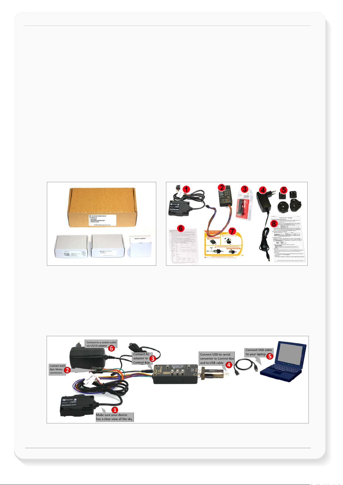
PROMOTION-KIT consists of 1 outer box with 3 small boxes inside. Before you start up the PROMOTIONKIT, make sure that your package includes the following items listed in table 1 below. If any item is missing
or damaged, please contact your vendor immediately.
Figure 1: PROMOTION-KIT delivery package.
Page 5 of 21
This confidential document is a property of FALCOM GmbH and may not be copied or circulated without previous permission.
Page 7

BOLERO40 Series Promotion Kit Version 1.0.1
Nr
Article name
Quantity
Description
BOLERO40 (BOX)
listed in chapter 2.2
Support
-
8 hours free technical support via skype, phone etc. for starting up your project.
Mounting instruction contains important information to assist personnel in the
of the device, insert the SIM card(s) and (re)place the internal battery.
Control-Box with a 50 cm long cable and an 8pin (2x4) connector at the end. It has a
USB to SERIAL
adapter
PC/Laptop.
4
Power Supply
1
Type
incl. UK/US/AU/EU adaptor
NR
PDF file name
Description
and the supported
Configuration Command Set for the FALCOM’s vehicle telematics devices.
[2]
BOLERO-40_Series_HardwareManual.pdf
Contains information about the hardware of the BOLERO45/41 device.
BOLERO45
or
BOLERO41
Battery 1 700 mAh rechargeable battery (already inserted and connected to the BOLERO45)
1
PREMIUM-FEATURES -
5 SIM-Card 1
6 Instruction sheet 1
7 Quick Setup Guide 1
8 Info-Sheet 1
BOLERO40-CONTROL-BOX
2 Control-Box 1
1
1 x BOLERO41 or BOLERO45 device (depending on customer request) pre-configured
and all supported Premium-features are activated. At the end of the cable there is an
8pin (2x4) connector that allows connection of the device to the Control-box.
All PREMIUM-FEATURES supported by the BOLERO45/41 device are activated by the
factory. For details how to use them refer to the corresponding Application Notes
Prepaid SIM card. Service fee includes 10MB of data transfer and 3 months access to
the FALCOM D2Sphere server for evaluation purposes.
installation of the unit.
Quick Setup Guide, containing the necessary information how to open/close the case
Contains log-in data to access the online documentation on the FALCOM website and
FALCOM D2Sphere frontend server for evaluation purposes.
RS-232 connector that allows USB connection to a PC using the USB-to-Serial
converter. This box looks the same as the BOLERO45' Control-Box, with the one
difference that it has only one 50 cm long cable instead of 2 cables like the
BOLERO45' Control-Box.
3
POWER-SUPPLY-BOX
1
Table 1: The list of items included in the PROMOTION-KIT.
USB-to-Serial converter with extension cable for connection of the control-box to the
FW7238/12
2.2 Related documents
In addition to this document, the following files comprise the full set of BOLERO40 series product manuals
and can be downloaded from the FALCOM web site (protected area). Downloading documents from the
FALCOM website:
1. Open your installed browser and enter "https://www.falcom.de/distributor-login/?origin=4"
2. Log-in using the logging data (Username & Password) available in the Info Sheet delivered with the
PROMOTION-KIT
3. Go to "Support" and select "AVL (FOX3, STEPPIII,.....)" from the "Documentation" selection box
4. This will list the supporting documents for all FALCOM’s vehicle telematics devices. Please, download
just the documents listed in the table below.
[1] AVL_PFAL_Command_Set.pdf
Contains the description of the internal firmware
Table 2: Documents for download from the FALCOM website (protected area)
Page 6 of 21
This confidential document is a property of FALCOM GmbH and may not be copied or circulated without previous permission.
Page 8

BOLERO40 Series Promotion Kit Version 1.0.1
NR
PDF file name
Description
FALCOM’s vehicle telematics device.
to a new firmware revision remotely via TCP.
This document provides all the necessary information how to connect 1-Wire
FALCOM D2Sphere-fleet documents
Downloading documents from the FALCOM website:
1. Open your browser and enter "https://www.falcom.de/support/documentation/application-notes/"
2. This will list the application notes for all FALCOM vehicle telematics devices. Please, download just the
application notes listed in the table below.
[3] AppNotes_ECO-DRIVE-GPS.pdf
[4] AppNotes_INDEXED_HISTORY.pdf
[5] AppNotes_Transform_history_data.pdf
[6] AppNote_Remote_update.pdf
[7] AppNotes_AVL_Installation_Guide.pdf
[8] AppNotes_1-Wire-Guide.pdf
[9] t4y_fleet_UsersGuide.pdf
Table 3: Documents for free download from the FALCOM website
Contains information about the using of ECO-DRIVE-GPS on FALCOM’s vehicle
telematics devices.
Contains information about the indexed history on FALCOM’s vehicle
telematics devices.
Contains information about the conversation of the history data stored in a
Contains information of how to upgrade FALCOM vehicle telematics devices
This document provides all the necessary information to allow your FALCOM
product to be properly and safely installed.
sensors to your FALCOM product and work with them.
This document provides all the necessary information how to get started and
work with FALCOM D2Sphere-fleet server application/frontend.
These PDF files are viewable and printable from Adobe Reader. If you do not have the Adobe Reader
installed, you can download it from
http://www.adobe.com.
Page 7 of 21
This confidential document is a property of FALCOM GmbH and may not be copied or circulated without previous permission.
Page 9
BOLERO40 Series Promotion Kit Version 1.0.1
3. GETTING STARTED
3.1 PROMOTION-KIT hardware set up
This chapter explains how to connect and set-up this PROMOTION-KIT.
Installing the PROMOTION-KIT in five steps:
1. Unpack the PROMOTION-KIT.
2. Connect the BOLERO45/41 unit to the control-box and PC and apply power.
3. Power up the control-box and charge the internal backup battery of the device.
4. Install the FALCOM Workbench software and start the evaluation of the BOLERO45/41 device
5. Access the online documentation from the FALCOM website using the login data available in the info
sheet supplied with PROMOTION-KIT.
3.2 Unpacking the PROMOTION-KIT
Unpack the contents as shown in the figure below. There is no external antenna included in the
PROMOTION-KIT, as the BOLERO45/41 has also internal GSM/GGNSS antennas.
Figure 2: Boxes inside the PROMOTION-KIT and the contents of the kit.
3.2.1 Connecting BOLERO45/41 to the control-box
1. Before starting initial operation, switch all switches on the Control-Box to "OFF" (factory default
setting) and make sure the device has a clear view of the sky so that the satellite signals can be
received.
2. Plug in the 8pin double row connector of cable of the device to the cable with 8pin double row
connector of the control-box. To unplug, press the "lever" on the back of this connector and pull it out.
Figure 4: Connecting PROMOTION-KIT to BOLERO45/41 and PC
Page 8 of 21
This confidential document is a property of FALCOM GmbH and may not be copied or circulated without previous permission.
Page 10

BOLERO40 Series Promotion Kit Version 1.0.1
3. Now, unpack the power supply from the box and plug it into the left input socket on the control-box
marked "INPUT 12.0V … 32.0V”. Then plug the AC adapter into the wall socket of your 220V electric
mains (to access British/American wall socket use the included UK/US adaptor accordingly).
4. The internal battery in the device may be shipped with a minimal charge and will need to be fully
charged before use. To charge the internal battery, follow the steps below:
a) After connecting the AC adapter to the Control-Box and into the wall socket, apply power to
the control box and BOLERO45/41 device by turning just the “+IN” switch to “ON” position.
Figure 5: Overview of the control-box top panel (+IN = ON)
b) Depending on the battery charge state, the charging time may by different but usually it
takes 2-3 hours to fully charge the internal battery.
5. After the battery is fully charged, unpack the USB to serial converter and the USB extension cable.
Remove the USB cover on the converter and connect the USB cable to the converter (1), see figure
below. Plug the serial port of the converter to the COM port of the control box (2). Finally, plug the
other end of the cable into a free USB port on your PC (3). This cable is used for communication
between the BOLERO45/41 and Workbench software for sending and receiving data as well as to
change the configuration stored in the BOLERO45/41 device.
Figure 6: Connecting the converter with the USB cable
6. Finally, power up the BOLERO45/41 device by turning the “IGN”-switch to "ON" position.
“+IN” It supplies power to the control box and the connected BOLERO45/41 device.
“IGN” It wakes up the BOLERO45/41 from IGN-Sleep mode.
Figure 7: Overview of the control-box top panel (IGN = ON)
Page 9 of 21
This confidential document is a property of FALCOM GmbH and may not be copied or circulated without previous permission.
Page 11
BOLERO40 Series Promotion Kit Version 1.0.1
3.2.2 Installing the FALCOM Workbench software and start evaluation
The following list shows the hardware requirements for Workbench software:
(a) PC with 700 megahertz or higher processor Intel Pentium II or compatible processor recommended
(b) 512 MB of RAM or higher recommended (512MB min. supported; may limit performance and some
features)
(c) 90 megabytes (MB) of available hard disk space (recommended 2 gigabytes)
(d) Keyboard and Mouse.
To be able to test your device with factory preloaded configuration or to change this configuration and load
your configuration into the BOLERO40, you need to install the Workbench evaluation software. Go to the
link below and download it: http://www.falcom.de/support/software-tools/falcom-workbench/. An install
shield will guide you through the installation. An integrated online help can be found after the installation
completes.
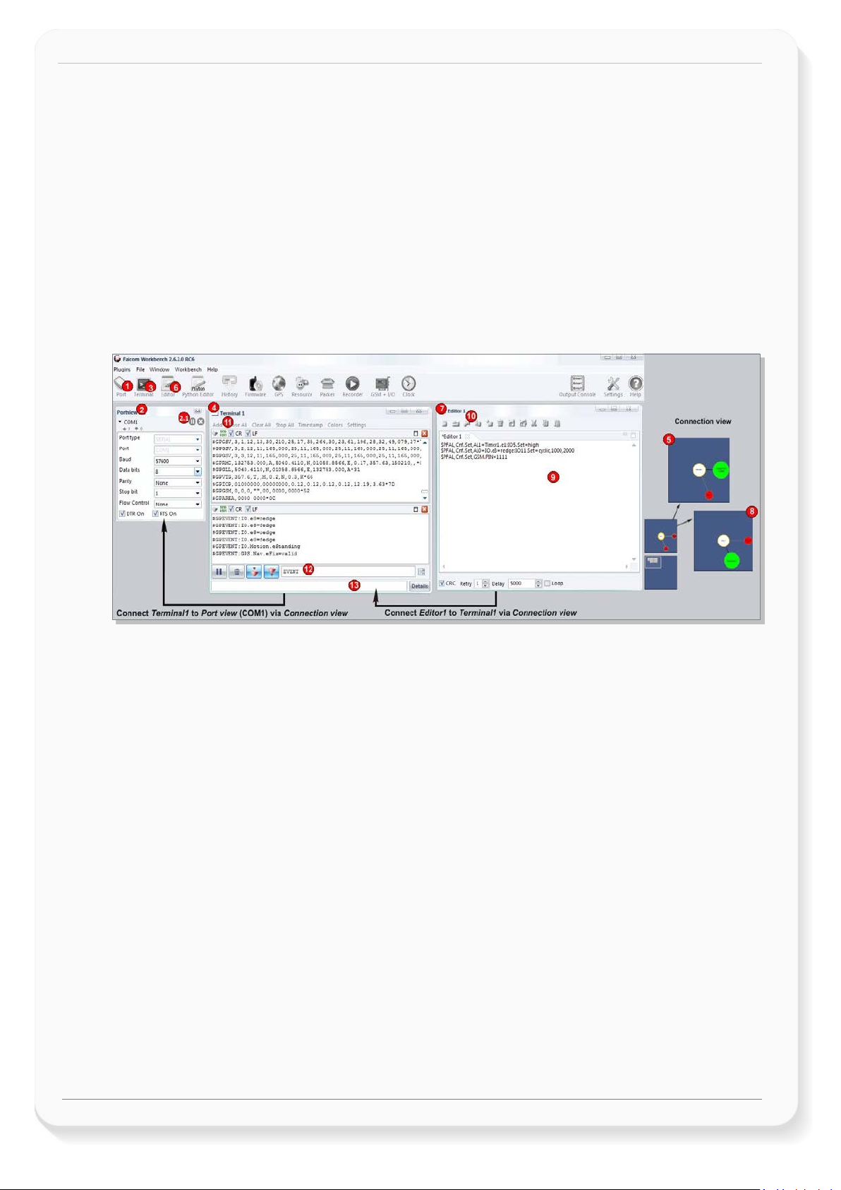
Figure 9: FALCOM Workbench software.
1. After completing the installation, start the Workbench.exe by double-clicking on it. Open a new COM
Port from the Toolbar (1), on the COM Port view (2) choose the Port where BOLERO45/41 is
connected (go to Device Manager > Ports > USB Serial Port (COMxx), where xx is the COM port to use),
define the port settings (115200 bps, 8 Data bits, No Parity bit, 1 Stop bit, None Flow control) and
finally, click the connect (play) icon (2.1) to open that COM Port. You can also get an online help in
HTML format if you click "Help" button on the upper-right corner.
2. Open a new Console from the Toolbar (3), click on the Console1 (4), then go to Connection view and
click on COMPort (5).
3. Open a new Editor from the Toolbar (6), click on the Editor1 (7), then go to Connection view and click
on Console1 (8).
4. To send commands to the BOLERO45/41 device, type them on the Editor (9) and then click on Start
sending configuration (10) or double click with left mouse each configuration line on the Editor (9)
individually.
5. To see all events generated by the BOLERO45/41 device, either open a new console “Console2” or on
the Console1 (4), click “Add” (11), type the text “GPEVENT” on input field (12), finally click the button
(13 )“Filter incoming”. A description how to operate with the Control-Box is given in chapter 4.
6. You have to load/save your configuration into your device before installing the device in the vehicle.
How to send data to a TCP-Server or SMS messages to a phone number/SMS server and how to
reconfigure the loaded configuration on the device, refer to the Related Documents [1]. A description
how the firmware on the BOLERO45/41 works is given in chapter 5.1.
3.2.3 Accessing online documentation
References to the online documentation are listed in chapter 2.2, related documents.
Page 10 of 21
This confidential document is a property of FALCOM GmbH and may not be copied or circulated without previous permission.
Page 12

BOLERO40 Series Promotion Kit Version 1.0.1
3.3 Customer Support
Users of the PROMOTION-KITS can receive assistance up to 8 hours through technical support team.
Contact our technical support through our web site at: http://www.falcom.de/support/support-form/
3.4 FALCOM D2Sphere server-frontend
The D2Sphere-fleet is a web-based tracking application that provides users with an easy-to-use interface
from where you can remotely monitor and view the location of the FALCOM AVL devices in real-time. The
D2Sphere online tracking software allows you to view the device history and device-generated event, view
reports, manage geofences as well as pull and change the factory-preloaded device configuration. After
the BOLERO45/41 is successfully powered up, open a web browser (IE or Firefox) and follow the
registration process as given on the enclosed slip of paper called „Info-Sheet“.
3.5 How does the sample configuration work ?
Once the BOLERO45/41 device is powered up, it tries automatically to register to the GSM network, attach
to the GPRS network and finally connect to the FALCOM trace4yor server using the factory-preloaded
configuration. The connection state of the GPRS and TCP services will be shown by the generated events
GSM.GPRS.eConnected and TCP.Client.eConnected telling you that the device is connected to the GPRS/TCP
server. These events are displayed on the Terminal in the Workbench. The device GPS location is shown on
the trac4you frontend server after log-in. Fore more details about the sample configuration, refer to the
chapter 5, A detailed explanation of the sample configuration. For more details about the D2Sphere server
refer to the Related Documents
[14].
Page 11 of 21
This confidential document is a property of FALCOM GmbH and may not be copied or circulated without previous permission.
Page 13

BOLERO40 Series Promotion Kit Version 1.0.1
Item
Description
INPUT (12V – 32V)
Input power supply for control-box and BOLERO45/41 device with 1.1 A fuse protected.
Item
Description
LED (+IN)
Lights when the +IN-switch is turned to ON.
LED (IGN)
Lights when the IGN-switch is turned to ON.
+IN - switch
This two-way-switch enables or disables power to the connected BOLERO45/41 unit. (To enable
power to the device, the Current- switch must be set to “ON“)
IGN - switch
This two-way-switch wakes up the BOLERO45/41 device from IGN-sleep mode and sets the IGN-pin
of the BOLERO45/41 to High or Low signal level for using the rising edge and falling edge events.
IO - switches
These pins have dual functions. All are controlled by the internal firmware of BOLERO40. Therefore,
nputs. Their function is controlled with
by changing the
or digital outputs. More details how to test these IOs, are given below.
Testing IOs as digital
When the reference IO (e.g: IO/2) is configured as digital input with "$PFAL,IO1.Config=DI,2,10", the
the position of the IO/2-Switch changes from "Digital IN - Low" to "Digital IN - High".
4. CONTROL-BOX - HARDWARE DESCRIPTION
This chapter gives you some information about the operation of the control box. It allows you to exercise
the function of all inputs and outputs on the BOLERO45/41 device without the need to add any other
external component to them. The components on the control-box can be identified from the figures below
showing the front, top, and the rear panels. Inside the control-box there is a 1-wire temperature sensor,
therefore you are able with corresponding PFAL commands to test also the 1-Wire interface on BOLERO40
series device.
4.1 Front panel overview
Figure 10: Front panel of the control-box.
A description of each of the items on the front panel is provided in Table 4.
Table 4: Front panel overview.
4.2 Top panel overview
Figure 11: Top panel of the control-box.
A description of each of the items on the top panel is provided in Table 5.
the user must define whether to use them as analog or digital pins. The configured digital pins can be
inputs or outputs while the analog pins can only be i
commands with $PFAL,IO1[2].Config=DI,1,10 or $PFAL,IO1[2].Config=AI,1,10
electrical behaviour of the reference pin to digital or analogue input (DI = Digital input; AI = Analogue
input). These three-way switches (from IO/2 to IO/3, while the IO/1 does not have any function – as
IO1 is not available for BOLERO40 series.) allow operation of the IOs either as digital/analogue inputs
inputs:
Page 12 of 21
This confidential document is a property of FALCOM GmbH and may not be copied or circulated without previous permission.
BOLERO45/41 device will generate a rising edge event "IO.e1=redge" and set the state of the IO/2 to
high "IO.s1=high", if:
•
Page 14

BOLERO40 Series Promotion Kit Version 1.0.1
Item
Description
and will generate a falling edge event "IO.e1=fedge" and sets its state to low "IO.s1=low", if:
the position of the IO /2 -Switch changes from "Digital IN - High" to "Digital IN -Low".
Testing
IOs as
When the reference IO (e.g: IO/2) is configured as analogue input with "$PFAL,IO1.Config=AI,2,10,
➒
➒
(see Fi g.
" position. This position has a
Send the configuration
" from the
➒
After the timer expires (1 second has passed), the red LED of the BOLERO45/41 (front side, next to
the BOLERO40 device, refer to the Related Documents [2].
Testing IOs as digital
When the reference IO (e.g: IO/2) is supposed to be used as digital output, there is no configuration to
4. Send the command "$PFAL,IO6.Set=low" to set it to Low.
Item
Description
Serial port 0
•
you have to calibrate first this IO the low and high voltages. To do it, perform the following steps (e.g.
analogue
inputs:
IO/1):
1. Switch the IO/2-Switch (IO/2) to "Digital IN - Low" position.
2. Send t he command "$PFAL,IO0.Calibrate,offset=0" from the W orkbench Editor
8) to BOLERO40.
3. Switch the IO/2-Switch (IO/2) to "Digital IN - High" position.
4. Send t he command "$PFAL,IO1.Calibrate,gain=15" from the Workbench Editor
8) to BOLERO40.
5. Switch t he IO/2-Switch (IO/2) to "Digital OUT / analogue IN
fixed voltage of approx. 6V.
(see Fig.
Now, you can configure an alarm (e.g. $PFAL,CNF.Set,AL31=Sys.Timer.e1&IO.s1>6.0:IO6.Set=high) to
switch on an LED (e.g. IO/3) when the voltage on the IO/3 is higher than e.g. 5.0 V. To test it, perform
the steps below:
6.
"$PFAL,CNF.Set,AL31=Sys.Timer.e0&IO.s2>5.0:IO13.Set=hpulse,5000
Workbench Editor ➒ (see Fig. 8) to BOLERO40.
7. Switch the IO/1-Switch (IO/2) to "Digital OUT / analogue IN" position.
8. Send the c ommand "$PFAL,Sys.Timer0.Start=single,1000" from the Workbench Editor
(see Fig. 8) to BOLERO40.
the 6pin accessory port) goes ON for 5 seconds and then turns OFF. For more details about the LED of
outputs:
be done in the firmware. To test it, perform the steps below:
1. Remove the available configuration for the IO/2 with
"$PFAL,IO0.Config="
2. Switch the IO/2-Switch to the "Digital OUT / analogue IN" position
3. Send the command "$PFAL,IO5.Set=high" to set it to High
Table 5: Components on the top panel of the control-box and their functionality
4.3 Rear panel overview
A description of each of the items on the rear panel is provided in Table 6.
Figure 12: Rear panel of the control-box.
With the serial-toUSB adapter supplied with promotion kit you are able to connect the control-box to
a PC and evaluate the connected BOLERO45/41 device.
Table 6: Item description on the rear panel of the control-box.
Page 13 of 21
This confidential document is a property of FALCOM GmbH and may not be copied or circulated without previous permission.
Page 15

Functions
Configuration alarms and their descriptions.
Tracking
$PFAL,CNF.Set,AL0=SYS.Device.eStart:SYS.TIMER1.start=cyclic,20000&SYS.TIMER0.start=cyclic,5000&SYS.T
IMER2.start=cyclic,2000
$PFAL,CNF.Set,AL1=SYS.Device.eStart:GPS.Nav.Position0=load0&GPS.Nav.Position1=load0&Sys.Timer3.Sta
rt=single,10000
AL1: Every time the BOLERO45 turns on or wakes up, it loads the saved Position from memory slot zero
$PFAL,CNF.Set,AL2=SYS.Device.eShutdown:GPS.Nav.Position0=save0&GPS.Nav.SaveLastValid
$PFAL,CNF.Set,AL3=SYS.Device.eShutdown:TCP.Client.Send,8,"<sfal.event text='shutdown'>"
AL3: Before the device goes in sleep mode, it sends a TCP packet to the server including the RMC GPS
with the text event ‘shutdown’.
$PFAL,CNF.Set,AL9=SYS.TIMER.e0&GPS.Nav.Position.s1>50&GPS.Nav.sFix=correct&GPS.Nav.sSpeed>2:GPS
.Nav.Position1=current&GPS.History.Write,0,""
$PFAL,CNF.Set,AL10=SYS.TIMER.e1&GPS.Nav.Position.s0>200&GPS.Nav.sSpeed>2:GPS.Nav.Position0=curr
ent&TCP.Client.Send,8,"<sfal.pos>"
TCP packet to the server including the GPRMC protocol and the user text <sfal.pos>.
$PFAL,CNF.Set,AL11=GPS.Nav.eChangeHeading&GPS.Nav.sSpeed>2:GPS.Nav.Position1=current&GPS.Nav.
Position0=current&GPS.History.Write,0,"HEAD"
$PFAL,CNF.Set,AL12=GPS.Nav.eChangeHeading&GPS.Nav.sSpeed>2:TCP.Client.Send,8,"<sfal.pos>"
sends a TCP packet to the server including the GPRMC protocol AND the user text ‘HEAD’.
$PFAL,CNF.Set,AL13=IO.e8=redge:Sys.Timer3.Start=single,2000&Sys.Timer4.Stop
AL13
$PFAL,CNF.Set,AL14=Sys.Timer.e3&IO.s8=high:TCP.Client.Send,8,"<sfal.trip.start>"&GPS.History.Write,20,"
<sfal.trip.start>"&GPS.Nav.Distance=0
TCP packet to the server including the GPRMC protocol, the user text <sfal.trip.start> and also it saves
BOLERO40 Series Promotion Kit Version 1.0.1
5. A DETAILED EXPLANATION OF THE SAMPLE CONFIGURATION
In the table below you find a detailed description of the configuration preloaded in the device shipped with
promotion kit. To call this configuration use either the command $PFAL,Cnf.Show or use the button “Read
current device configuration” from the Editor of the Workbench software. See chapter 3.1.4, Fig. 9.
AL0: Every time the BOLERO45 turns on or wakes up, it starts three cyclic Timers: Timer0, Timer1 and
Timer2 with repeat timer events that occur every time a 20000, 5000 and 2000 of milliseconds elapses.
These timer events will be used later in other alarms to start or stop actions (PFAL commands).
E.g. Timer0 event (Sys.Timer.e0) is used in AL9 to save GPS position data every 20 sec. in the history if
other set conditions (like: displaced distance is > 50m and GPS fix is valid) are true.
to GPS.Nav.Position0 and starts a Timer3 with a single timer event that occurs once, after 100000 of
milliseconds (10 sec.).
AL2: Before the device goes in sleep mode, it saves both its position from GPS.Nav.Position0 to memory
slot zero and the last valid position in the corresponding configuration parameter.
protocol and the user text <sfal.event text='shutdown'>, telling the server D2Sphere its current location
AL9: Each time the cyclic Timer0 runs out, the displaced distance from the position 1 is greater than 50
meters, the GPS is corrected and the speed is > 2m/s, then the device sets the new position to current
position and saves the position in the history (Data logging) inside the device.
AL10: Each time the cyclic Timer1 runs out, the displaced distance is greater than 200 meters, the GPS is
corrected and the speed is > 2m/s, then the device sets the new position to current position and sends a
AL11: Each time the predefined angle (course) is exceeded and the speed is > 2m/s, then the device sets
the new position to current position AND it saves the position in the History (Data logging) with the user
text "HEAD"
AL12: Each time the predefined angle (course) is exceeded and the speed is > 2m/s, then the device
: Each time the Ignition is turned ON (IO.e8=redge), the device starts Timer3 with a single timer
event that occurs once, after 2000 of milliseconds (2 sec.) and stops running the Timer4.
AL14: When the single Timer3 runs out and the status of the Ignition is still high, then the device sends a
Page 14 of 21
This confidential document is a property of FALCOM GmbH and may not be copied or circulated without previous permission.
Page 16

BOLERO40 Series Promotion Kit Version 1.0.1
Functions
Configuration alarms and their descriptions.
the user text in the history (data logging) with the user text <sfal.trip.start>.
$PFAL,CNF.Set,AL15=IO.e8=fedge:Sys.Timer4.Start=Single,2000&Sys.Timer3.Stop
$PFAL,CNF.Set,AL16=Sys.Timer.e4&IO.s8=low:TCP.Client.Send,8,"<sfal.trip.stop
dist='&(NavDist)'>"&Sys.Timer5.Start=single,60000
AL16: When the Timer4 runs out and the Ignition pin is still OFF, then the device sends a TCP packet to
dynamic variable: &(NavDist.km) or &(NavDist.miles)
$PFAL,CNF.Set,AL17=Sys.Timer.e5&IO.s8=low:Sys.Device.Sleep=IGN
LED status
$PFAL,CNF.Set,AL4=SYS.Power.eDropped:IO13.Set=cyclic,200,200
red LED (IO13) starts flashing 200msON/200ms OFF.
$PFAL,CNF.Set,AL5=SYS.Power.eDetected:IO13.Set=high
$PFAL,CNF.Set,AL6=Sys.Device.eStart&Sys.Power.sVoltage>=9:IO13.Set=high
LED (IO13) gets solid.
$PFAL,CNF.Set,AL7=Sys.Device.eStart&Sys.Power.sVoltage<9:IO13.Set=cyclic,200,200
AL7
$PFAL,CNF.Set,AL8=TCP.Client.ePacketSent:IO12.Set=lpulse,200
pulse of 200ms.
$PFAL,CNF.Set,AL18=Sys.device.eStart&GPS.Nav.sFix=invalid:IO13.Set=cyclic,200,200
$PFAL,CNF.Set,AL19=GPS.Nav.eFix=valid:IO13.Set=high
$PFAL,CNF.Set,AL20=GPS.Nav.eFix=invalid:IO13.Set=cyclic,200,200
$PFAL,CNF.Set,AL27=Sys.device.eStart&GPS.Nav.sFix=valid:IO13.Set=high
$PFAL,CNF.Set,AL21=GSM.eOpfound:IO12.Set=cyclic,200,200
$PFAL,CNF.Set,AL26=GSM.eOplost:IO12.Set=low
$PFAL,CNF.Set,AL22=GSM.GPRS.eConnected:IO12.Set=cyclic,400,400
$PFAL,CNF.Set,AL25=GSM.GPRS.eDisconnected&GSM.sOpValid:IO12.Set=cyclic,200,200
AL15: When the Ignition is turned OFF (IO.e8=fedge), the device starts Timer4 with a single timer event
that occurs once, after 2000 of milliseconds (2 sec.) and stops running the Timer3.
dist='&(NavDist)'>"&GPS.History.Write,20,"<sfal.trip.stop
the server including the GPRMC protocol, the user text <sfal.trip.stop> and the driven distance in meters
&(NavDist). It also saves the user text in the history (data logging) with the user text <sfal.trip.stop>, the
driven distance in meters and starts Timer5 with a single timer event that occurs once, after 60000 of
milliseconds (60 sec.)
//If another unit of the driven distance is needed, then replace &(NavDist) with the corresponding
AL17: When the Timer5 runs out and the status of the Ignition pin is still low, then the device goes in
sleep mode with the wakeup parameter IGN. The wakeup parameter ‘IGN’ means, the device will wake
up whenever the Ignition pin is switched to high.
AL4: When the external/main power drops and the BOLERO45 runs on its internal backup battery, the
AL5: When the external/main power is applied and the BOLERO45 runs on its internal backup battery,
the red LED (IO13) gets solid.
AL6: When the BOLERO45 turns on or wakes up from Sleep and external/main power is applied, the red
: When the BOLERO45 turns on or wakes up on its internal backup battery and the external power is
below 9VDC, the red LED (IO13) starts flashing 200msON/200msOFF.
AL8: Each time the BOLERO45 sends a TCP message to the server, the green LED (IO12) initiates a low
AL18, 19, 20, 27: Every time the BOLERO45 turns on or wakes up, it checks all the time for GPS fix and
sets the orange LED (IO13) either blinking (AL19, AL27) or turns it ON (AL18, AL27) depending if the
device has a GPS fix (AL19, AL27) or not (AL18, AL20).
AL21, 26: Once the device has found a GSM operator, the green LED (IO12) will blink and when it has lost
a GSM operator, the LED will turn OFF.
Page 15 of 21
This confidential document is a property of FALCOM GmbH and may not be copied or circulated without previous permission.
Page 17

BOLERO40 Series Promotion Kit Version 1.0.1
Functions
Configuration alarms and their descriptions.
AL22, 25
$PFAL,CNF.Set,AL23=TCP.Client.eConnected:IO12.Set=high
$PFAL,CNF.Set,AL24=TCP.Client.eDisconnected&GSM.sOpValid:IO12.Set=cyclic,400,400
Configuration
$PFAL,CNF.Set,DEVICE.BAT.CHARGEMODE=eco
$PFAL,CNF.Set,DEVICE.BAT.MODE=auto
Automatically switching between external power and internal battery power source depending on the
$PFAL,GPS.NAV.GNSS=GPS,GLONASS,Beidou
Acquires and tracks 3 GNSS systems concurrently: GPS,GLONASS,Beidou
$PFAL,CNF.Set,DEVICE.COMM.SERIAL0=cmd,7F
$PFAL,CNF.Set,DEVICE.COMM.TCP.CLIENT=cmd,60
$PFAL,CNF.Set,DEVICE.GPS.AUTOCORRECT=on,5.0,58,50,10,50
and maximal acceleration of 50 m/s.
$PFAL,CNF.Set,DEVICE.GPS.CFG=4
$PFAL,CNF.Set,DEVICE.GPS.HEADING=25
Heading tolerance is set to 25 degrees. Each time this angle is exceeded, the event
$PFAL,CNF.Set,DEVICE.GPS.TIMEOUT=1,30
$PFAL,CNF.Set,DEVICE.NAME=BOLERO45
$PFAL,CNF.Set,DEVICE.PFAL.SEND.FORMAT="$",CKSUM,"","$<end>"
$<end>. These settings can be changed based on your server requirements.
$PFAL,CNF.Set,PPP.PASSWORD=blau
$PFAL,CNF.Set,PPP.USERNAME=blau
Required string (username) for the Chap and Pap authentication methods over PPPP to attach the device
: Once the device is attached to GPRS services, the green LED (IO12) will blink and when it is
detached from that services but it still has a valid GSM operator, the green LED (IO12) will blink fast.
AL23, 24: Once the device is connected to TCP server, the green LED (IO12) goes ON and when it is
disconnects from that server but it still has a valid GSM operator, the green LED (IO12) will blink slower
than when it detaches from GPRS services.
parameters
Starts charging if the voltage of the internal battery drops to less than 3.9V and terminates charging
when the battery is full-charged.
power source currently available. External DC power supply has priority, if it is higher than 8 V.
The serial port 0 is set into the command operation mode with protocols and events output enabled.
The serial port 0 is set into the command operation mode without protocols and events output enabled
Enables filtering of GPS auto correction to calculate a valid GPS fix using maximal allowed PDO of 5.0,
maximal speed limit of 58 m/s, maximal allowed distance error of 50, drop count incorrect position of 10
At least 4 satellites must be in use to consider a GPS fix as valid.
GPS.Nav.eChangeHeading occurs, and the driving direction resets to zero.
Restarts the GPS receiver to do a new search for visible GPS satellites, if within this time no valid fix is
available.
Device name is defined to BOLERO45. To use another name replace ‘BOLERO45’ to your string and send
it to the device.
The syntax of the PFAL messages is defined to start each line with the character ‘$’, followed by the user
text and terminated by a NMEA compatible checksum and <CRLF>. The complete message(s) end(s) with
Required string (password) for the Chap and Pap authentication methods over PPPP to attach the device
into the GPRS network. This setting is provider-dependant.
Page 16 of 21
This confidential document is a property of FALCOM GmbH and may not be copied or circulated without previous permission.
Page 18

BOLERO40 Series Promotion Kit Version 1.0.1
Functions
Configuration alarms and their descriptions.
into the GPRS network. This setting is provider-dependant.
$PFAL,CNF.Set,GPRS.APN=Public4.m2minternet.com
APN (Access Point Name) name that your network operator has provided to you to connect the device to
the GPRS/Internet. This setting is operator or provider dependant.
$PFAL,CNF.Set,GPRS.AUTOSTART=1
$PFAL,CNF.Set,GPRS.DIAL=ATD*99***1#
$PFAL,CNF.Set,GPRS.QOS=0,0,0,0,0
GPRS network.
$PFAL,CNF.Set,GPRS.QOSMIN=0,0,0,0,0
$PFAL,CNF.Set,GPRS.TIMEOUT=1,600000
$PFAL,CNF.Set,GSM.BALANCE.DIAL=*100#
GSM dial number for retrieving balance information
$PFAL,CNF.Set,GSM.OPLOST.RESTART=1,1200000,8
$PFAL,CNF.Set,PROT.3DP=0
$PFAL,CNF.Set,PROT.AREA=0
device.
$PFAL,CNF.Set,PROT.BIN=0
$PFAL,CNF.Set,PROT.GGA=1
$PFAL,CNF.Set,PROT.GLL=1
$PFAL,CNF.Set,PROT.GSA=1
GSA protocol is activated. To deactivate this protocol replace 1 to 0 and send it to the device.
$PFAL,CNF.Set,PROT.GSM=1
$PFAL,CNF.Set,PROT.GSV=1
GSV protocol is activated. To deactivate this protocol replace 1 to 0 and send it to the device.
$PFAL,CNF.Set,PROT.IOP=1
Enables automatic attachments to the GPRS network. If the GPRS network connection gets lost, it tries to
reconnect automatically as soon as the network is available again.
The V.250 'D' (Dial) command causes the device to enter the V.250 online data state.
Quality of Service Profile used when the device sends an Activate PDP Context Request message to the
Minimum acceptable profile checked by the device against the negotiated profile returned in the
Activate PDP Context Accept message.
Detaches the device from GPRS network if no TCP communication available within the timeout.
Reinitializes the GSM engine periodically until a GSM operator is found.
3DP protocol (motion sensor data) is deactivated. To activate this protocol replace 0 to 1 and send it to
the device.
AREA protocol (area states) is deactivated. To activate this protocol replace 0 to 1 and send it to the
BIN protocol (FALCOM) is deactivated. To activate this protocol replace 0 to 1 and send it to the device.
GGA protocol is activated. To deactivate this protocol replace 1 to 0 and send it to the device.
GLL protocol is activated. To deactivate this protocol replace 1 to 0 and send it to the device.
GSM protocol is activated. To deactivate this protocol replace 1 to 0 and send it to the device.
Page 17 of 21
This confidential document is a property of FALCOM GmbH and may not be copied or circulated without previous permission.
Page 19

BOLERO40 Series Promotion Kit Version 1.0.1
Functions
Configuration alarms and their descriptions.
$PFAL,CNF.Set,PROT.RMC=1
RMC protocol is activated. To deactivate this protocol replace 1 to 0 and send it to the device.
$PFAL,CNF.Set,PROT.START.BIN=$!
$PFAL,CNF.Set,PROT.VTG=0
$PFAL,CNF.Set,TCP.CLIENT.CONNECT=1,5.35.253.3,4444
Enables the connection to the remote server and specifies the IP address and the Port number of the TCP
$PFAL,CNF.Set,TCP.CLIENT.DNS.TIMEOUT=86400
$PFAL,CNF.Set,TCP.CLIENT.LOGIN=1
Sends the login data automatically to the remote server after requesting the TCP server for establishing a
connection.
$PFAL,CNF.Set,TCP.CLIENT.PING=1,240000
$PFAL,CNF.Set,TCP.CLIENT.SENDMODE=2
Safe and non-volatile transmission mode.
$PFAL,CNF.Set,TCP.CLIENT.TIMEOUT=300000,30000
$PFAL,CNF.Set,GSM.PIN=1111
Enters/saves the PIN code of the SIM card inserted into the device..
$PFAL,GSM.Band=auto
Factory settings
It consists of configuration settings preloaded at the factory during the manufacturing of BOLERO45 series
The user has the possibility of personalizing this configuration and with the help of
the device to factory settings, the device must be configured in order to operate
referring to your application (see chapter for more details
AddOns*
The Promotion Kit is shipped with some sample functions. To extend its functionality, you can refer to the
(define reference GPS points along a specific route where the vehicle should track. Alerts when
DR8+ Blue Dot Receptor iButton Reader
: DS18(B)20
IOP protocol is activated. To deactivate this protocol replace 1 to 0 and send it to the device.
BIN protocol starts with ‘$!’. To use other charates replace ‘$!’and send it to the device.
VTG protocol is deactivated. To activate this protocol replace 0 to 1 and send it to the device.
server to connect to.
The length of time (in seconds) to keep the DNS cache valid.
Activates sending of pings and specifies the amount of time, in milliseconds, on which a ping will be sent
to the remote server.
Period of time in milliseconds that the device will wait for a response and between two connection
attempts when TCP connection fails.
The GSM band to be used by the device is set to ‘auto’. The device registers to that frequency band
currently available. Refer to the PFAL command set for the supported settings.
devices.
$PFAL,Sys.Device.FactoryReset command it is possible to overwrite the User Settings with the Factory
Settings. After reseting
setting file „AddOns.conf“ and modify it according to your needs. Please contact support (see chapter 3.2)
for more details about the file „AddOns.conf“.
eCodrive (This feature includes instant and results for driving activities and driver behaviors such as: TripStart /
TripStop / Harsh-Brake / Harsh-Acceleration / Harsh-Turn) - refer to the
Waypoints
Tilting (> 45°) and crash detection (1 x Tilt alert every 15 sec.)
1Wire (iButton + Temp. Sensors) Supported iButton: DS1402D-
exiting/entering that route)
Cable with DS1982 iButton and DS1921 iButton (MAXIM). Supported 1Wire Temp.Sensor
(MAXIM). Refer to the Related documents [13]
Related documents [6]
HINT: The user text (in quotation marks “ ”) started with “sfal” indicates an event on our D2Sphere server. This event text is only
supported on our server, use other text formats for your own server.
Page 18 of 21
This confidential document is a property of FALCOM GmbH and may not be copied or circulated without previous permission.
Page 20

BOLERO40 Series Promotion Kit Version 1.0.1
6. APPENDIX
6.1 How does the BOLERO40 Series firmware operate?
BOLERO45/41 device can be easily integrated into a variety of new applications. It contains an
independent-customized software that provides even greater performance and flexibility for its users and
system integrators to develop high-performance applications. The concept of the device is based on a
simple implementation for a wide range of applications with low costs and high flexibility. The software
enables you to configure, to track, control and monitor the BOLERO45/41 device via SMS, as well as allows
you set and poll the configuration remotely over Internet from the remote server. The software comprises
a set of word-like commands termed “PFAL”. Each of these causes the system BOLERO45/41 either to take
a particular action or to read or set a particular configuration. The software provides the basic configuration
settings needed when the system starts up and is used as starting points for the creation of user
applications. The development of user applications is based on the advanced event-handling features
provided by the operating software. The exact point at which you configure the BOLERO45/41 unit depends
on your application you want to develop. Events are triggered automatically at system run-time and
manually when the inputs change.
A part of events triggered at system run-time can be:
Geo-fence violations (in/out)
Changes to analog inputs (signal exceeds the range)
Over speed detection (exceeding the speed limits)
Specific distance reached (distance reached event)
Towing detection (park events)
Moving/acceleration detection and many other features.
A part of events triggered manually can be:
Changes on digital or analog inputs (car' door open/close events, ignition on/off events)
BOLERO45/41 executes actions in response to an event or state(s) or in any combination. BOLERO45/41 can
also execute direct actions immediately after the user sends a command (via SMS, TCP, RS-232) to the
device. When an event is triggered, the alarms related to that event are automatically sent either over GSM
(SMS, Data call) and/or via TCP, or internally used to switch On/Off something in remote e.g. activating a
Buzzer.
A part of alarms that can be executed can be:
Message generation (route verification arrival/departure notification via SMS/TCP)
Activation of outputs in a number of ways (activate a buzzer )
Data logging activation (stores the data inside the device
Handling of incoming messages of any type (Activation on SMS text type)
Vehicle doors Lock & Unlock
Vehicle engine starter Disable and Enable
Handling of Timers, Triggers and Counters, and many others
Above are listed just a few software features and for a full view of the set of events, states, alarms,
configurations and their functionalities refer to the Related Documents [1].
Page 19 of 21
This confidential document is a property of FALCOM GmbH and may not be copied or circulated without previous permission.
Page 21
BOLERO40 Series Promotion Kit Version 1.0.1
Hint
$PFAL,Cnf.Set,TCP.CLIENT.CONNECT=1,2222.222.222.222,1111 (enter your IP and Port)
Hint: Activate GPRS autostart to reconnect automatically when GPRS network connection gets lost.
automatically sent to your remote server. For more details refer to the Related Documents [1].
6.2 Installing your own SIM card and replacing the internal battery
To insert your own SIM card into the BOLERO40' SIM holder and replace the internal battery by a new one,
follow the steps shown in the package insert.
6.3 Conn ecting BOLERO40 series to your server
When using your own SIM card and another TCP server, the following table shows the basic configuration
settings that should be done in the BOLERO45 device to register the device in the GSM network and enable
internet connection to your TCP-Server. These configuration settings should be done locally via serial port
connection. After inserting your SIM card and powering up the device, send the following commands
(marked in red) from Workbench Editor
: Settings required for a GPRS attachment (please enter your mobile operator's data)
$PFAL,Cnf.Set,GPRS.APN=internet.t-d1.de (enter your operator's APN)
SETUP
SETUP
$PFAL,Cnf.Set,GPRS.QOS=3,4,3,0,0
$PFAL,Cnf.Set,GPRS.QOSMIN=0,0,0,0,0
$PFAL,Cnf.Set,PPP.USERNAME=t-d1 (if your operator requires)
$PFAL,Cnf.Set,PPP.PASSWORD=gprs (if your operator requires)
Hint: Settings required for a TCP connection (enter your server settings)
Where: 2222.222.222.222 - is the IP-address of the TCP server to be connected;
1111 - is the TCP port number of the TCP server to be connected;
➒ (see Fig. 8) to the BOLERO40.
SETUP
SETUP
BOLERO45/41
sends login data
to your server
$PFAL,Cnf.Set,GPRS.AUTOSTART=1 (default = 0)
Hint: Enter the SIM PIN to register the BOLERO45 device into the GSM network:
Where: 1111 - is the PIN of the inserted SIM card.
$PFAL,Cnf.Set,DEVICE.PIN=1111 (enter the PIN of your (used) SIM card)
Table 8: Adapt device configuration settings to your application conditions.
Hint: After establishing TCP connection with your remote server, the following ServerLogin data is
$<MSG.Info.ServerLogin>
$DeviceName=AVL Device
$Security=0
$Software=avl_3.0.0 (FBNCT0xFUk80NSByZXY6MDEtTlVhAgEA)
$Hardware=BOLERO45 rev:01-NUa
$LastValidPosition=$GPRMC,131040.000,A,5040.4089,N,01058.8536,E,0.01,162.02,250917,,
$IMEI=357520070404948
$PhoneNumber=+491134501024564
$LocalIP=10.208.151.168
$CmdVersion=2
$SUCCESS
$<end>
Table 9: Login data sent automatically from the BOLERO45/41 to your remote server when the
device starts up.
Page 20 of 21
This confidential document is a property of FALCOM GmbH and may not be copied or circulated without previous permission.
 Loading...