

Page 1
User Manual
BMS123 Smart
Page 2

Introduction
After the introduction of affordable LiFePO4 batteries, off-grid solutions became available for wide
public. It is vital that such batteries are charged very carefully. In other words, they can easily be overcharged, or over-discharged. Cell-temperature and current are also very important, in order to
guarantee a long life.
The GWL Battery Management System ( or : BMS ) is primarily intended for prismatic LiFePO4LiFeYPO4-cells, but can also be adapted by the end-user for other cells like Li-Ion and LiPo, provided the
cell-voltage is in the range of 2V to 5V.
Keep the batteries in perfect condition
The drawing below shows that your expensive batteries are in good hands with 123 electric.
The system sets the coulomb counter to 100% when either all cells get to V-bypass or one cell reaches Vmax. (You can change these settings with the PC software by yourself.)
Calibrating the coulomb counter to 100% is important, as otherwise small errors will appear, because of
changes in the charging efficiency, aging of the batteries etc. etc.
The width of the green (safe) area, can also be selected by yourselves. If you use 90 Ah cells, for instance,
and you only want to use 60% of the capacity, you can enter 60% of 90 Ah = 54 Ah in the field for Cellcapacity.
Page 3
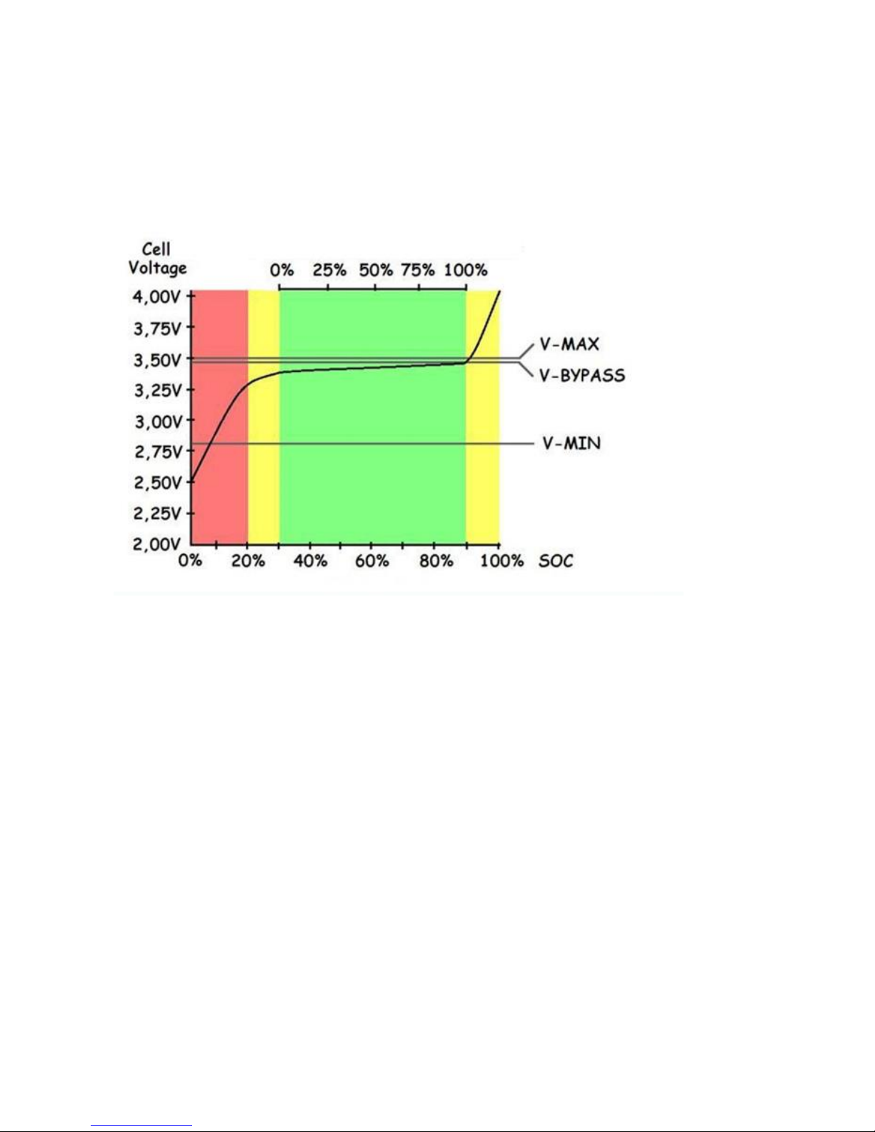
Conclusion : the upper limit is safe-guarded by entering V-max / V-bypass, and the lower limit by V-min.
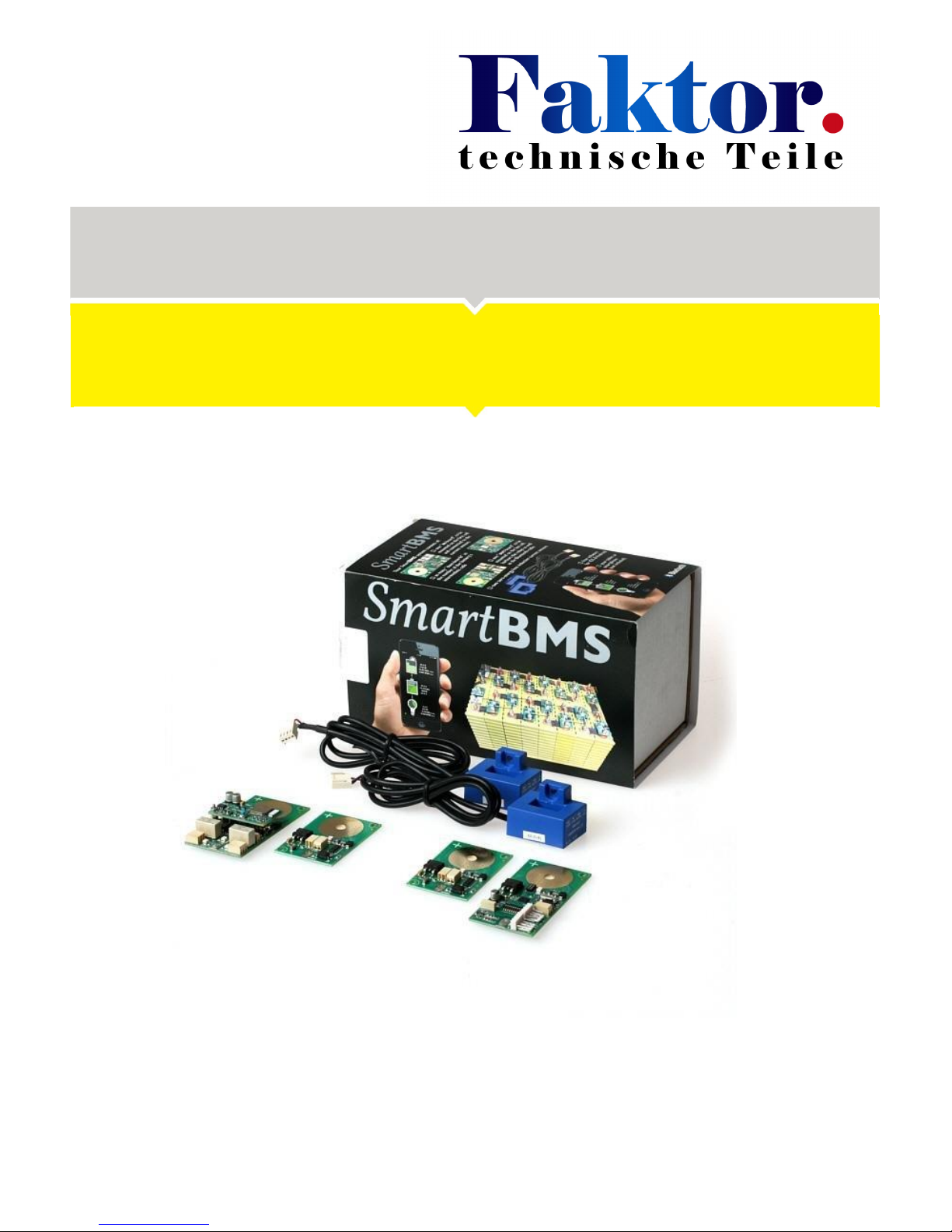
Package contains (12 Volt, 4 cells)
- IN Cell Board
- OUT Cell Board
- 2 Cell Boards
- 2 Current sensors
- Piece of 0,75 mm² wire for the interconnections
- Connector unlock tool
Page 4

Specification
Placing the cell modules
Please be aware that your battery-pack contains a large amount of energy, which can be potentially
dangerous. Use isolated spanners, to prevent any short circuits. High inrush currents, causing arc-ing (
sparks ) and ultra-high electromagnetic levels, can easily damage electronic circuits.
We therefore strongly recommend to always FIRST connect the so called "large current connections"
in a new setup, and THEN separately connect the BMS-boards.
A good way of doing this is indicated on photo number one. After thorough cleaning of the cell-poles,
the copper strips are bolted-on. Don't forget to also attach wires to the first and last cell in the same
way, and connect these to the solar panels, MPPT, charger and the load.
Item
Specifications
Idle Current of the BMS-IN / OUT Modules
inclusive current sensors and standby Bluetooth
< 2 mA
OUT Module current when Bluetooth
connection is active
<25mA
Idle Current BMS-modules
< 100 uA
Balancing Current
1 Amp.
Number of Cells
2 - 255
Current-sensors
100 Amp.
Resolution
10 Bit A/D converter
App compatibility
iOS, Android
Page 5
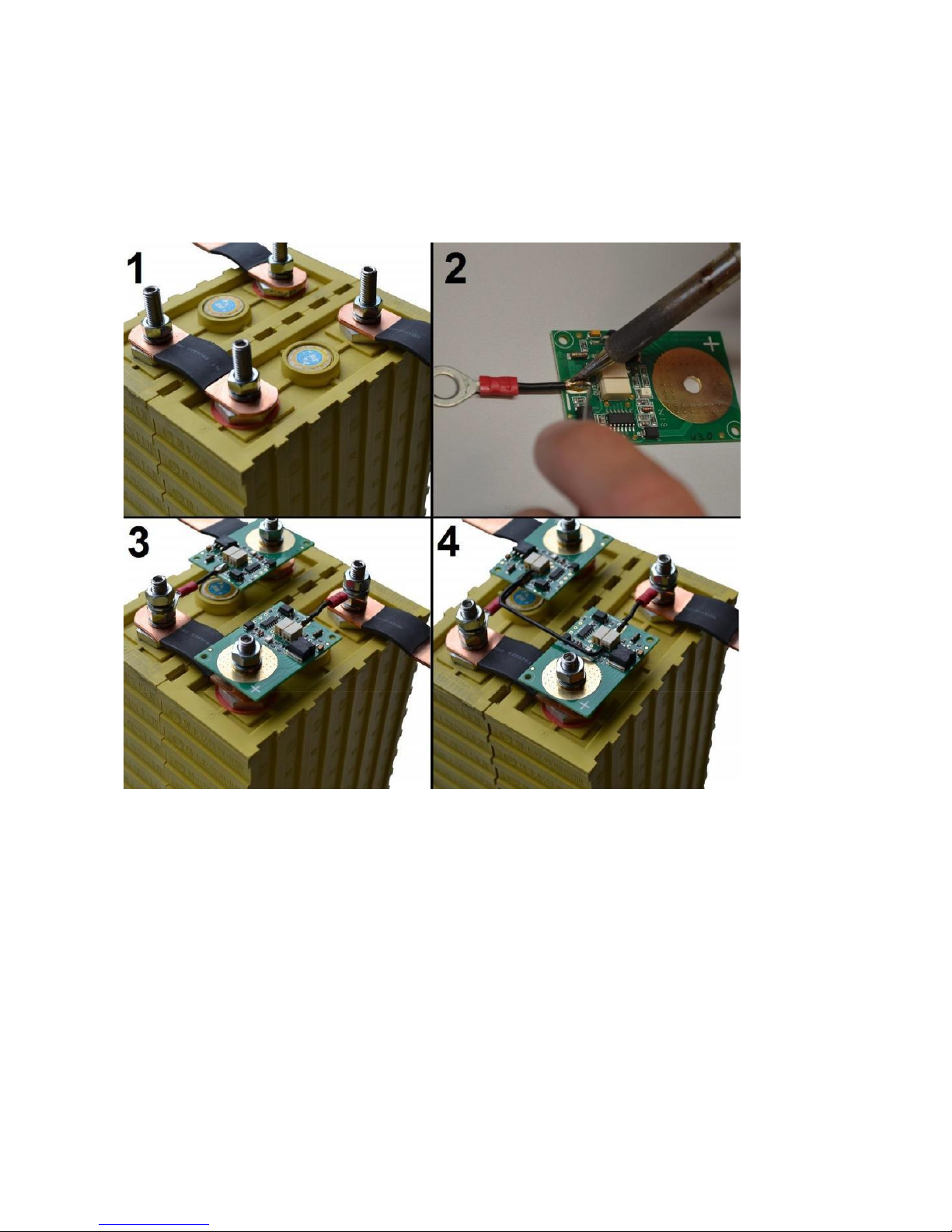
Mounting the IN Module
Start to mount the IN-Board on the first cell. It is important this is the cell on the minus (-) side of the battery
pack. Solder a wire on the solder pad of the IN-Board. (Photo 2) Connect this wire to the minus (-) side of the cell.
After the IN-Board is connected the LED will start blinking every second, this shows the IN-Board is trying to send
out data messages to the following cell board.
Install a current sensor in the incoming power line (solar panels, PMMT, charger) and connect this current sensor
to the IN-Board connector”J1” marked “I-1”. Install the other current sensor in the power line of the consumers
(inverter) and connect this sensor to the IN-Board connector ”J2” marked “I-2”. Make sure the arrow on the
current sensor is pointing in the right direction. The direction where the current is flowing (see picture on the
following page).
Note: when only using 1 current sensor, connect this sensor to J1.
Page 6

Mounting the „Between“ cell Modules
After the IN-Board was installed, please proceed by the cell boards. Now, prepare the BMS-boards as shown
on photo number two. Use thick solid-copper wire for this, for optimum accuracy. (the bypass-current has
to flow through these wires)
Take your time: the result has to look good!
The BMS module always has to be mounted on the 'plus' pole of the cell. This '+' is also indicated on the cell
modules. Connect all the modules as shown in photo number three.
Mounting the OUT module
On the last cell (+ side of the battery pack) the OUT-Board has to be installed. This works the same way
as the other cell boards. It’s normal you will hear some clicking relays when you power up the OUT
board.
Cell boards interconnections
After all cell boards are installed the interconnection can be made. Start the interconnection of the IN-Board
to the following cell board. Make a connection from the single connector marked “OUT” on the IN-Board to
the double connector position 1 Marked “IN” on the following cell board. Please be careful while you’re
doing this in order to prevent a short circuit. The single wire is now under power. Do not touch any other
part of circuit by this wire except the correct connector. It could damage the board. After you have made
the interconnection between the IN-Board and the first cell board you will notice the green LED on the next
cell board will flash as well every second. This confirms the cell board was correct installed and the
interconnection between the cell boards are made correct. Now go on with the other cell boards. Make
connections from the double connector position 1 market “OUT” to the next cell board connector position 1
market “IN” If the flashing LED’s stop somewhere in the middle of the cell chain there is an error, in this case
check the wiring.
A four cells 12 volt system needs three connections:
IN-Board J4 “OUT” Cell-Board “IN” position 1
Cell-Board “OUT” position 1
Cell-Board “IN” position 1
Cell-Board “OUT” position 1
OUT-Board J1 “IN”
Page 7
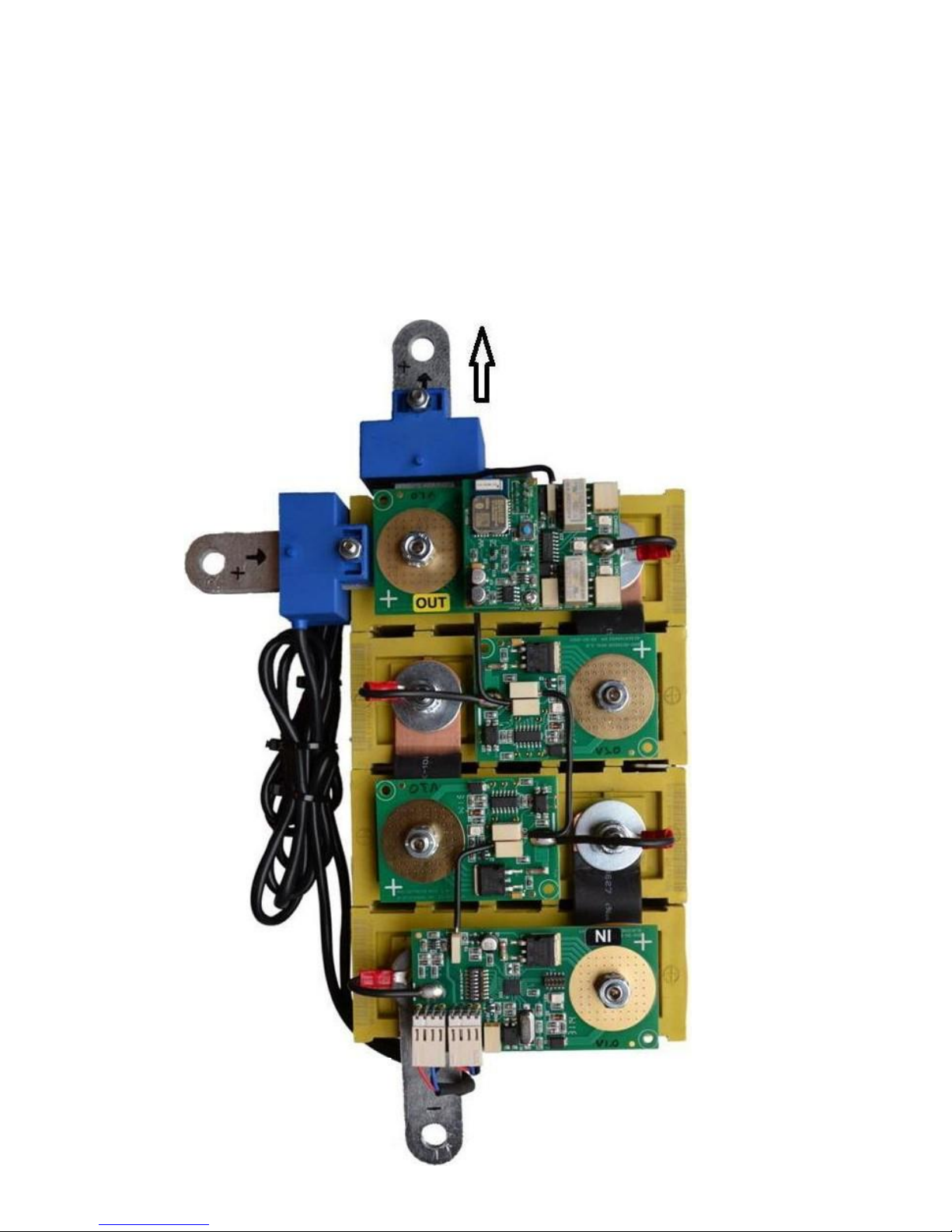
The
picture
below
shows a
basic
setup of a 12
Volt
battery pack
Page 8
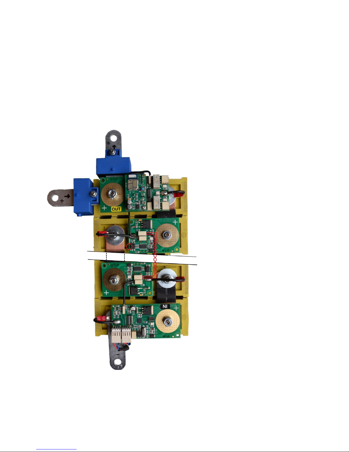
The picture below shows a setup with separated battery banks.
When the battery pack has separated battery banks the interconnection has to be changed to prevent
interference from other components in the system. The data connection has to be galvanic isolated. This can be
done by the following procedure:
Page 9

1- Cut of the PCB track between the two gold dots. ( red circled in the picture above )
Use a twisted pair cable and use both terminals.
IN-Board 'option switch' functions
Settings
The option switches can be changed when the system is active.
The table below shows you the functions of the option switches.
Important: Don't use switch number 8, this will overwrite hidden factory settings
Switch:
1 2 3 4 5 6 7
Function:
Fast
message
V-
Bypass
Bigger
blind
spot
Set zero
Mode
V-Bypass
ON
Messages every 0,5 Sec.
OFF
Messages every 1,0 Sec.
ON
Blind spot around zero AMP enable
OFF
Blind spot around zero AMP disable
OFF
Auto zero inactive
ON
Auto zero active
OFF
Normal mode (recommended)
ON
Critical mode
OFF
OFF
OFF
V-Bypass 3,4 Volt
OFF
OFF
ON
V-Bypass 3,5 Volt
OFF
ON
OFF
V-Bypass 3,6 Volt
OFF
ON
ON
V-Bypass 3,7 Volt
ON
OFF
OFF
V-Bypass 4,0 Volt
ON
OFF
ON
V-Bypass 4,1 Volt
ON
ON
OFF
V-Bypass 4,2 Volt
ON
ON
ON
V-Bypass 4,3 Volt
Option switch nr 1: The frequency of the cell board messages can be changed by these option switch. For fastest
information set the switch to ON, for saving energy set the switch to OFF.
Option switch nr 3: To prevent the current sensor is too sensitive around 0 Amps and this will cause
miscalculations in the SOC calculation, enable option switch 3. Now the current sensor has a little blind spot
around zero. ( this function is available in version 1,1 or newer )
Option switch nr 4: When the current sensors need to be calibrated follow the next procedure: Make sure there
is running absolutely no current through the current sensors during the zero calibration procedure. On the IN
Page 10

module you will find the option switches. Set option switch number 4 to the ON position. Now the “Auto zero”
procedure will be active. The currents on the App screen will show 0 Amps in a couple of seconds. Set the option
switch number 4 back to the OFF position again.
Option switch nr 5 (v1.5+): OFF (recommended): the BMS works in normal mode. The SOC is reset to 100% when
all cell voltages are at or above Vbypass. The relays are controlled by the BMS charge/discharge algoritm. Please
see section “Algoritm” for more info.
ON: the BMS does not act on SOC anymore and only switches the relays off in critical conditions like
communication error, too low voltage, too high voltage, too low temperature and too high temperature. The SOC
is reset to 100% if the total pack voltage is at or above Vbypass x Number of cells.
Option switch 2, 6 and 7: Set option switch 2, 6 and 7 in the right positions for the Bypass voltage you like.
See table for details.
Hidden factory settings
The settings below are normally pre-programmed during the production.
For programing other current sensors or change the number of cells follow the next
procedure:
Set all switches below in the right positions for current sensor and number of cells and toggle
switch 8 ON and OFF again.
The hidden settings are now stored in the BMS. Set the switches back in the original positions.
Please be aware it could be necessary to follow the current sensor calibration procedure
again.
Page 11

Switch:
1 2 3 4 5 6 7
Function:
Current
sensor
Number of cells
OFF
OFF
OFF
25 Amp
OFF
OFF
ON
50 Amp
OFF
ON
OFF
100 Amp (Default)
OFF
ON
ON
250 Amp
ON
OFF
OFF
400 Amp
ON
OFF
ON
500 Amp
ON
ON
OFF
-
ON
ON
ON
-
OFF
OFF
OFF
OFF
4 Cells
OFF
OFF
OFF
ON
8 Cells
OFF
OFF
ON
OFF
12 Cells
OFF
OFF
ON
ON
16 Cells
OFF
ON
OFF
OFF
20 Cells
OFF
ON
OFF
ON
24 Cells
OFF
ON
ON
OFF
28 Cells
OFF
ON
ON
ON
32 Cells
ON
OFF
OFF
OFF
48 Cells
ON
OFF
OFF
ON
64 Cells
ON
OFF
ON
OFF
80 Cells
ON
OFF
ON
ON
96 Cells
ON
ON
OFF
OFF
128 Cells
ON
ON
OFF
ON
156 Cells
ON
ON
ON
OFF
204 Cells
ON
ON
ON
ON
255 Cells
The App
First connection
Go to the App store for Apple devices and search for “BMS123 Smart”. Install the BMS123 Smart App on
your Apple device. For Android devices go to the Play store and search for “BMS123 Smart”. Install the
App on your Android device. Enable the Bluetooth functionality of your device.
Start the App, You will see an overview of an off-grid system. Tab the screen to show the title bar on
the top of the screen. Tab settings to open the settings section.
In case of the first connection push the little blue button on the OUT Board to wake up the
Page 12

Bluetooth section of the OUT-Board. Now your BMS will be discovered, Tab on the discovered
BMS123 Smart device to make a connection. The App will ask for a password, this password is stored in
the BMS to prevent everybody with a Bluetooth device can control your BMS. The standard password
is “1234”. After the connection has been made it’s time to configure the system.
Normally the BMS will search for Bluetooth devices every 30 seconds. This is done to save energy,
because a BMS is to protect, balance and monitor battery packs while consuming as less as possible
energy. So normally it can take at much 30 seconds before the BMS will be discovered. If the
connection has been made one time before, the device will re-connect automatically when you
start the App the next time. Every time you like to direct connect press the blue button.
Settings
Solar peak power: Set the maximum power of your incoming energy source, for example solar
panels. If the system contains 10 solar panels of 250 Watt each, the total power of 2,50 kW has to be
configured.
Inverter peak power: Set the maximum power of the consumers, for example an inverter.
When your inverter can supply 5 kilo Watt, 5,00 kW has to be configured.
Battery capacity: The battery capacity can of course be set to the total capacity of the battery pack.
We advise however to take only 75% of the rated capacity, to comply with cell aging and temperature
effects.
Change PIN: It is strongly recommended to change the password of the BMS to prevent intruders can
sabotage the system. Tab the “change PIN” line and follow the instructions.
Clear energy counters: Totals of incoming and outgoing energy will be stored into the BMS. If you
like to set these total counters to zero, tab the “Clear energy counters” line and follow the
instructions.
V min: If one of the cells gets below this minimum cell voltage threshold the “Vl“ warning indicator on
the battery details screen is switched on. The capacity will be set to 0% SOC and of course the “allow
to discharge” relay to control external devices will be switched off.
V max: If one of the cells gets above this maximum cell voltage threshold the “Vh“ warning indicator on
the battery details screen is switched on. The “allow to charge” relay to control external devices (solar
charger) will be switched off.
Page 13

V bypass: This is the voltage where you want all the cells to end up. Above this Voltage the cell modules
start to dissipate 1 Ampere to balance the cells. This setting can be changed with the option switched
on the IN-board and will only be displayed.
T min: If one of the cells gets below this minimum cell temperature threshold the “Tl“ warning
indicator on the battery details screen is switched on.
T max: If one of the cells gets above this maximum cell temperature threshold the “Th“ warning
indicator on the battery details screen is switched on.
Charge restart: When the battery pack capacity is 100% SOC, In case of all cells are above the Bypass
threshold the charge relay switched OFF and switches ON again if the capacity is below the
programmable “Charge restart”. This is to prevent toggling relays.
Discharge restart: The load relay will be switched off if the battery pack capacity is 0% or one of the
cells goes below the programmable minimum cell voltage, and switches on again if the capacity is
above the programmable “Discharge restart”.
Prevent auto-lock: Enabling this function prevent the device goes into sleep mode.
Show simulator: If you don’t have an BMS123 Smart but you like to discover the App, you can run a
simulator.
Page 14
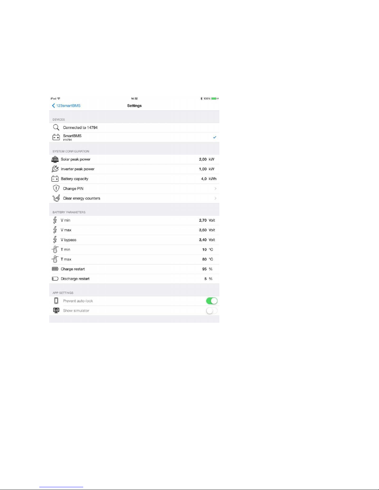
After the settings has been done, Tap the “< BMS123 Smart” button to show up the overview
Dashboard
The overview dashboard shows you all information you like to know.
The Solar panel shows the status of the incoming energy, next to this graphic presentation you
will find details like: Incoming charge current, Incoming power, harvest energy today, total of
harvest energy.
The battery shows the SOC ( State of charge ) of the battery pack. Next to this graphic presentation
you will find details like: State of charge percentage, Incoming / outgoing current of the battery,
Stored power in kWh, Incoming / outgoing power, Total battery pack voltage.
Page 15
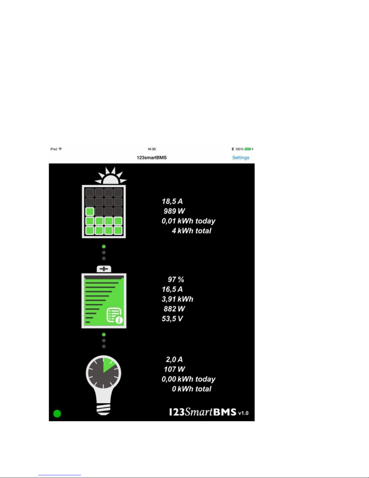
The light bulb shows the status of the outgoing energy, next to this graphic presentation you will
find details like: consumed current, consumed power, consumed energy today, total of consumed
energy.
When you Tap the “ i ” sign off the battery you will enter the battery details section.
Page 16
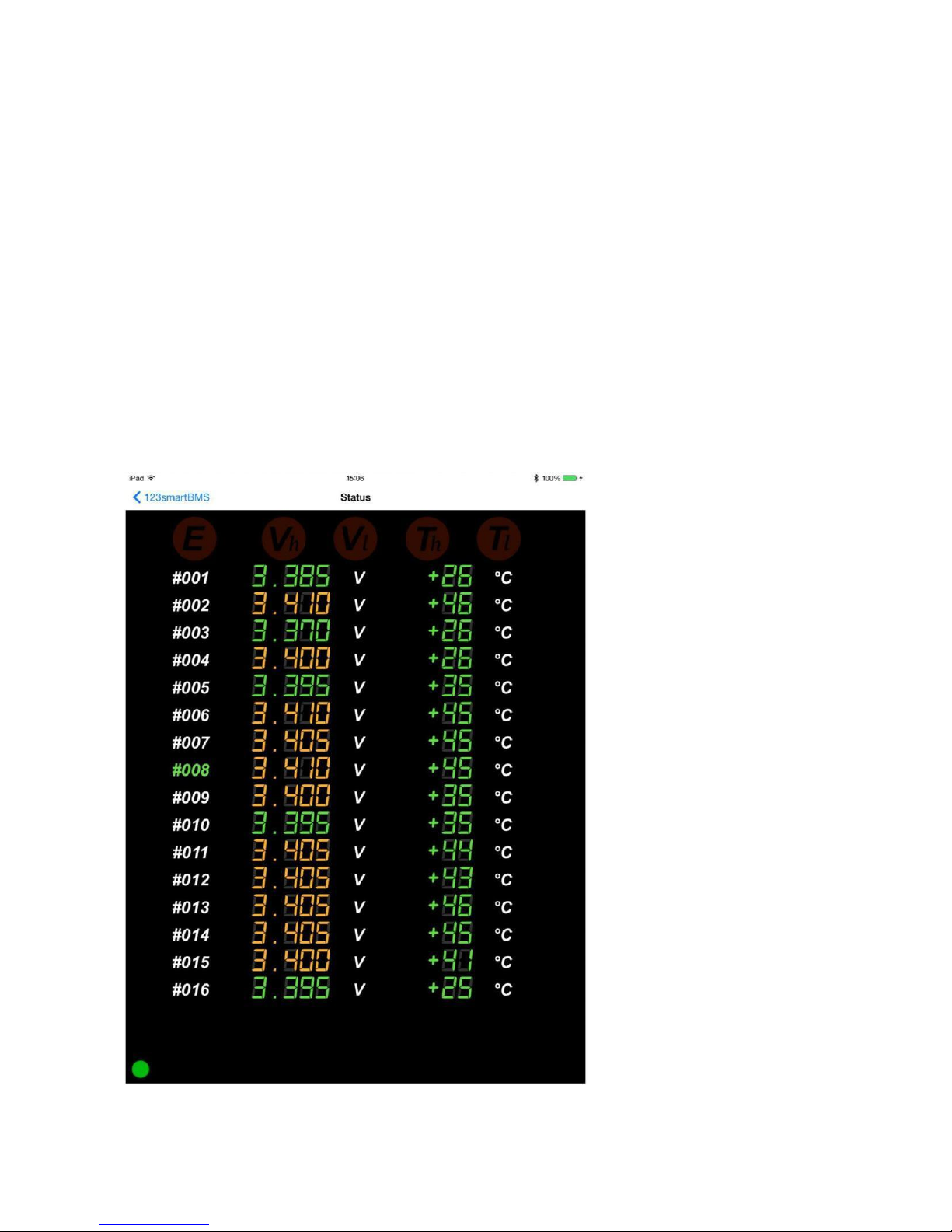
Battery details
The battery details shows you detailed info of the battery pack. Voltage and temperature of each cell
is displayed. Please be aware the temperature during bypass mode is much higher than the really cell
temperature. Green values are in the safe range, yellow values shows balancing cells and red values
are out of the safe range cells (above V max or below V min for example)
On top of the screen five warning lights will show critical errors. “E” Cell board communication error,
“Vh” Exceeding maximum cell voltage, “Vl” Exceeding minimum cell voltage, “Th” exceeding maximum
cell temperature, “Tl” exceeding minimum cell temperature.
Page 17

Controlling external components
On the OUT Module you will find two bi stable signal relays to control external components of your off-
grid system. This can be “solar chargers”, “Maximum power point trackers”, “inverters”, etc. An example
is the “enable” pin on many Victron inverters. The maximum current through these relays may be 1
ampere.
Charge relay
There is one relay to control incoming energy components of the system, like MPPT, solar charger et.
This relay is called the “CHARGE” relay. When charging is allowed the green CHARGE LED next to the
CHARGE relay will flash every second.
When charging is allowed Pin 1 and 2 of the CHARGE relay contacts (See OUT-Board details ) are closed.
(Pin 2 & 3 are open)
When charging is NOT allowed Pin 2 and 3 of the CHARGE relay contacts are closed. (Pin 1 & 2 are open)
Note: when switching inductive loads like a relay/contactor, make sure there is a protection against
flyback of the coil. A simple example is the flyback diode parallel to the coil.
Load relay
The other relay is to control outgoing energy components of the system, like inverters or other
consumers. This relay is called the “LOAD” relay. When discharging is allowed the green LOAD LED next
to the LOAD relay will flash every second.
When discharging is allowed Pin 1 and 2 of the LOAD relay contacts (See OUT-Board details ) are closed.
(Pin 2 & 3 are open).
When discharging is NOT allowed Pin 2 and 3 of the LOAD relay contacts are closed. (Pin 1 & 2 are open).
Note: when switching inductive loads like a relay/contactor, make sure there is a protection against
flyback of the coil. A simple example is the flyback diode parallel to the coil.
Algoritm
Charging is not allowed when one of the cells reaches the programmed “V-MAX” limit. Charging will be
allowed again after the “State of charge” has decreased to the value of the “Charge Restart” percentage
and all cells are below “V-Max”.
Discharging is not allowed when one of the cells goes below the programmed “V-MIN” limit. Discharging
will be allowed again after the “State of charge” has increased to the value of the “Discharge Restart”
percentage and when all cells are above ”V-MIN”.
Page 18
Discharging and charging will be stopped when there is a communication error. For example when there
is a loose contact in the string of cells. In this case the OUT module has no information of the cells before,
and will stop charging and discharging for safety reasons.
Discharging and charging will be both stopped when the temperature limits will be exceeded.
Module details
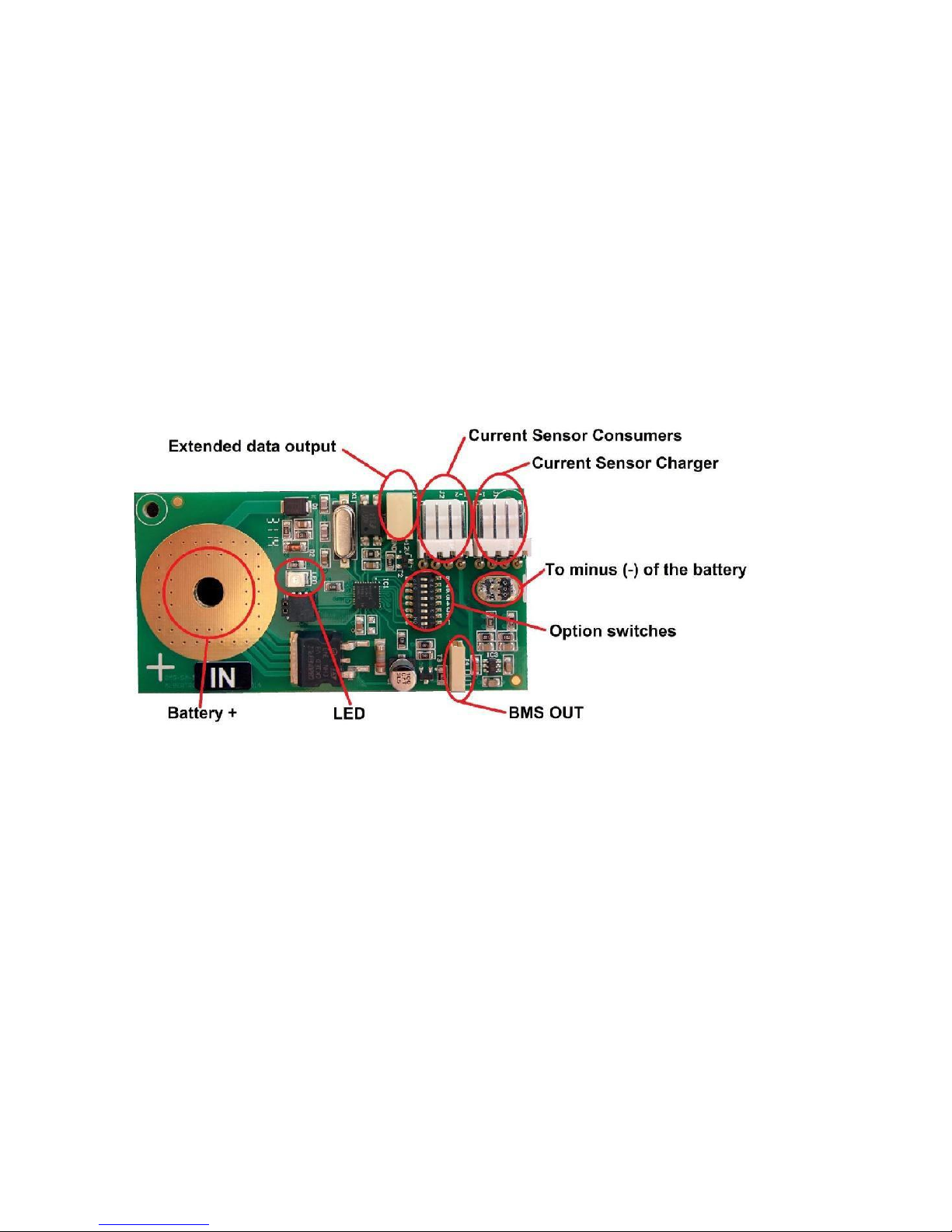
In Board
Battery + Mount hole for the 'plus'-pole of the cell.
LED Indicator LED, Flashes when data will be send, continuous ON when the
bypass mode is active
BMS OUT Interconnection connector for the data link to the next cell board
Option switches See page 7
To minus (-) of the battery Solder a wire on the solder pad and connect this wire to the minus (-)
side of the cell.
Current sensor charger Connector for the current sensor of the incoming current (solar)
Current sensor consumers Connector for the current sensor of the outgoing current (consumers)
Extended data input Data input
Page 19
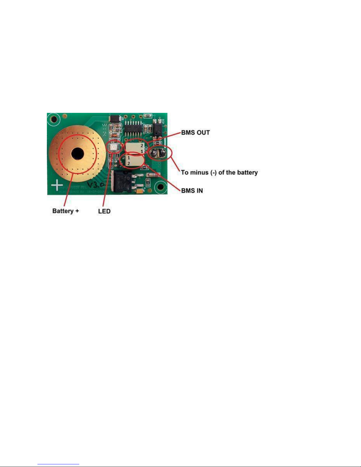
Between Cell boards
Battery + Mount hole for the 'plus'-pole of the cell.
To minus (-) of the battery Solder a wire on the solder pad and connect this wire to the minus (-)
side of the cell.
LED Indicator LED, Flashes when data will be received / send, continuous
ON when the bypass mode is active
BMS IN Data input from the previous cell board or IN-Board. Use the inner
connector hole marked with the text IN
BMS OUT Data output to the next cell board or OUT-Board. Use the inner
connector hole marked with the text OUT
Page 20
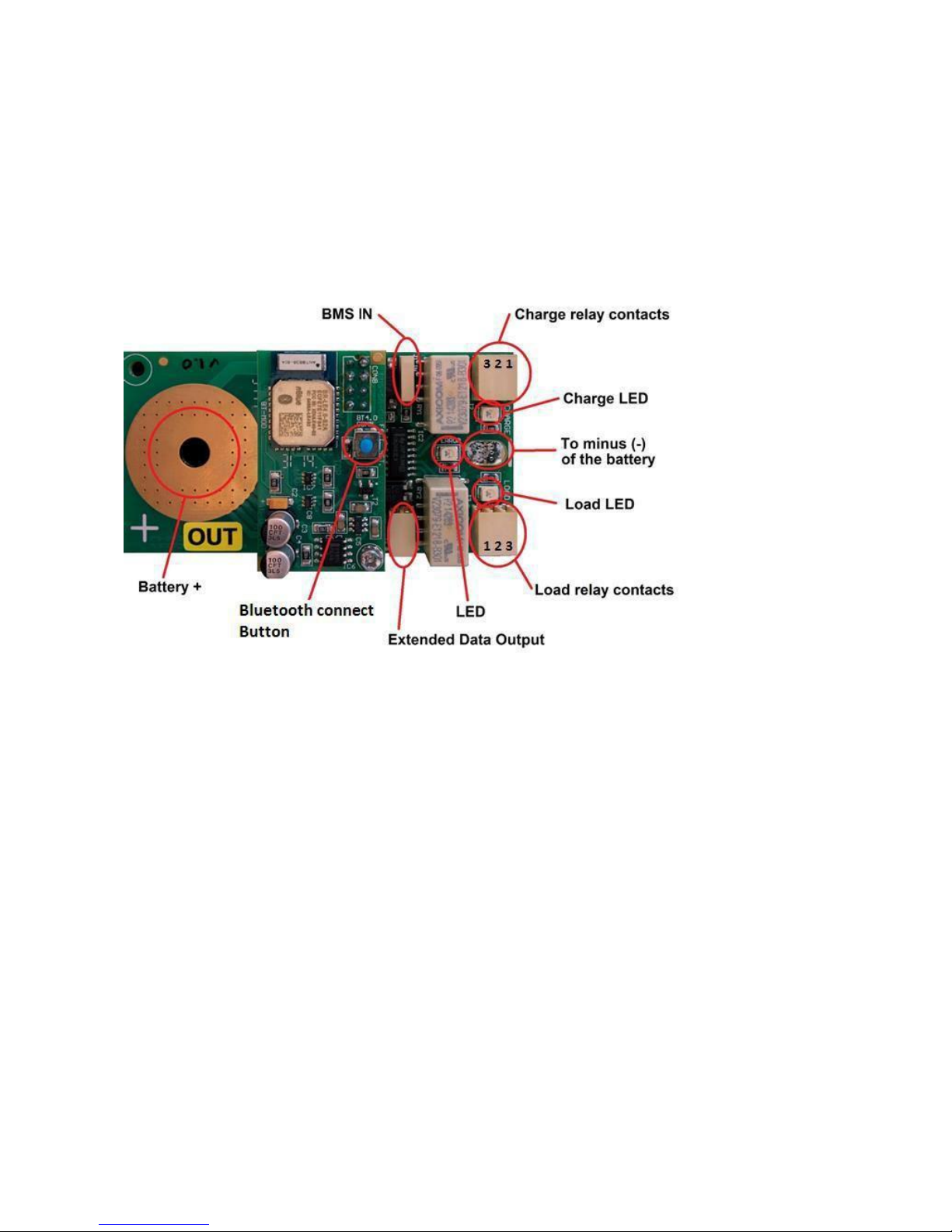
Out Board
Battery + Mount hole for the 'plus'-pole of the cell.
To minus (-) of the battery Solder a wire on the solder pad and connect this wire to the minus (-)
side of the cell.
LED Indicator LED, Flashes when data will be received, continuous ON
when the bypass mode is active
Load LED Flashes when consuming energy is allowed, load relay is active
Charge LED Flashes when charging energy is allowed, charge relay is active
BMS IN Interconnection connector for the data link to the previous cell board
Connection button Direct connect button for Bluetooth devices
Charge relay contacts Relay for cutting off chargers, MPPT, solar chargers etc. In case of full
batteries
Load relay contacts Relay for cutting off consumers like invertors, etc. In case of empty
batteries
Extended data output Data output for external modules
Page 21

FAQ:
Communication error No battery data on the app and the “E” sign will light ON in the battery
details tab of the App. Check the flashing LED’s on the string of cells. The position where the LED’s
stop flashing is the location of the problem. Check wiring or replace cell modules.
Forgot my password Press and hold the Bluetooth button for 5 seconds, the password will be set
the standard “1234”.
Reset the OUT-Module Disconnect the OUT Module of the battery cell. Press and hold the
Bluetooth button while you re-connect the OUT Module on the cell.
Current sensor isn’t zero in idle mode Make sure there is running absolutely no current through
the current sensors during the zero calibration procedure. On the IN module you will find the
option switches. Set option switch number 4 to the ON position. Now the “set to zero” procedure
will be active. The currents on the App screen will show 0 Amps in a couple of seconds. Set the
option switch number 4 back to the OFF position again.
Faktor
GmbH
83059 3D Spinnereiinsel Kolbermoor
Deutschland, European Union
www.faktor.de
 Loading...