

fakro ZWG1 User Manual

User manual of ZWG1 controller
Contents
1.Description..........................................................................................................................................................2
2.Installation of ZWG1 controller..........................................................................................................................3
3.Controller programming .....................................................................................................................................4
3.1.Adding device to network (INCLUDE function)........................................................................................5
3.2.Associating device with a pair of buttons on the controller (ASSOCIATE function)................................6
3.3.Associating another controller with the network (LEARN MODE)...........................................................7
3.4.Deleting device from a pair of controller buttons (DELETE function) ......................................................8
3.5.Excluding device from the network (EXCLUDE function)........................................................................9
3.6.Restoring default settings in the controller (DEFAULT function)............................................................10
3.7.Removing SECONDARY controller from the network............................................................................10
4.Technical parameters.........................................................................................................................................10
5.Battery replacement...........................................................................................................................................11
6.WARRANTY....................................................................................................................................................12
11.11.15 NC818 1/16 ©2012, FAKRO
GB
1. Description
The ZWG1 (wall keyboard) enables remote control of electronic accessories compatible with the
“Z-Wave” system, e.g. ZWS12 or ZWS30 motors for operating FAKRO roof windows. The ZWG1 controller
operates individually 1 or more devices simultaneously. It is possible to control up to 231 devices (all devices
will work at the same time).
The ZWG1 controller is equipped with a two-way “Z-Wave” communication radio module. For
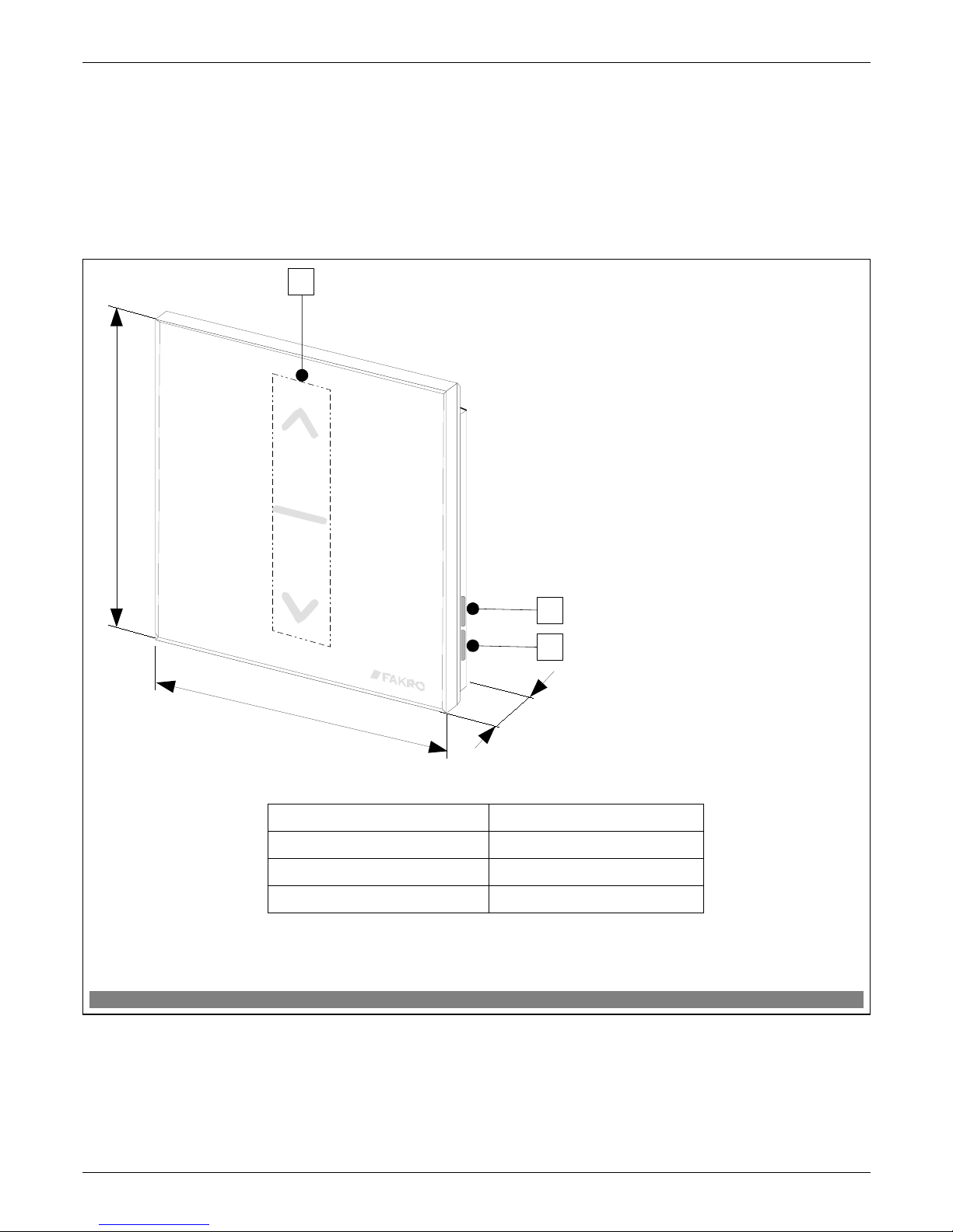
communication, the Z-Wave module exploits radio wave frequency of 868,42 MHz. In Figure 1, there is
presented a general view of the ZWG1 keyboard with description of available buttons and signaling.
11.11.15 NC818 2/16 ©2012, FAKRO
Figure 1: ZWG1 keyboard
Dimension ZWG1
A 80 [mm]
B 80 [mm]
C 15 [mm]
1. Functional button “In/Ex”.
2. Functional button “FK”.
3. Controlling buttons.
A
2
B
C
3
1
2. Installation of ZWG1 controller
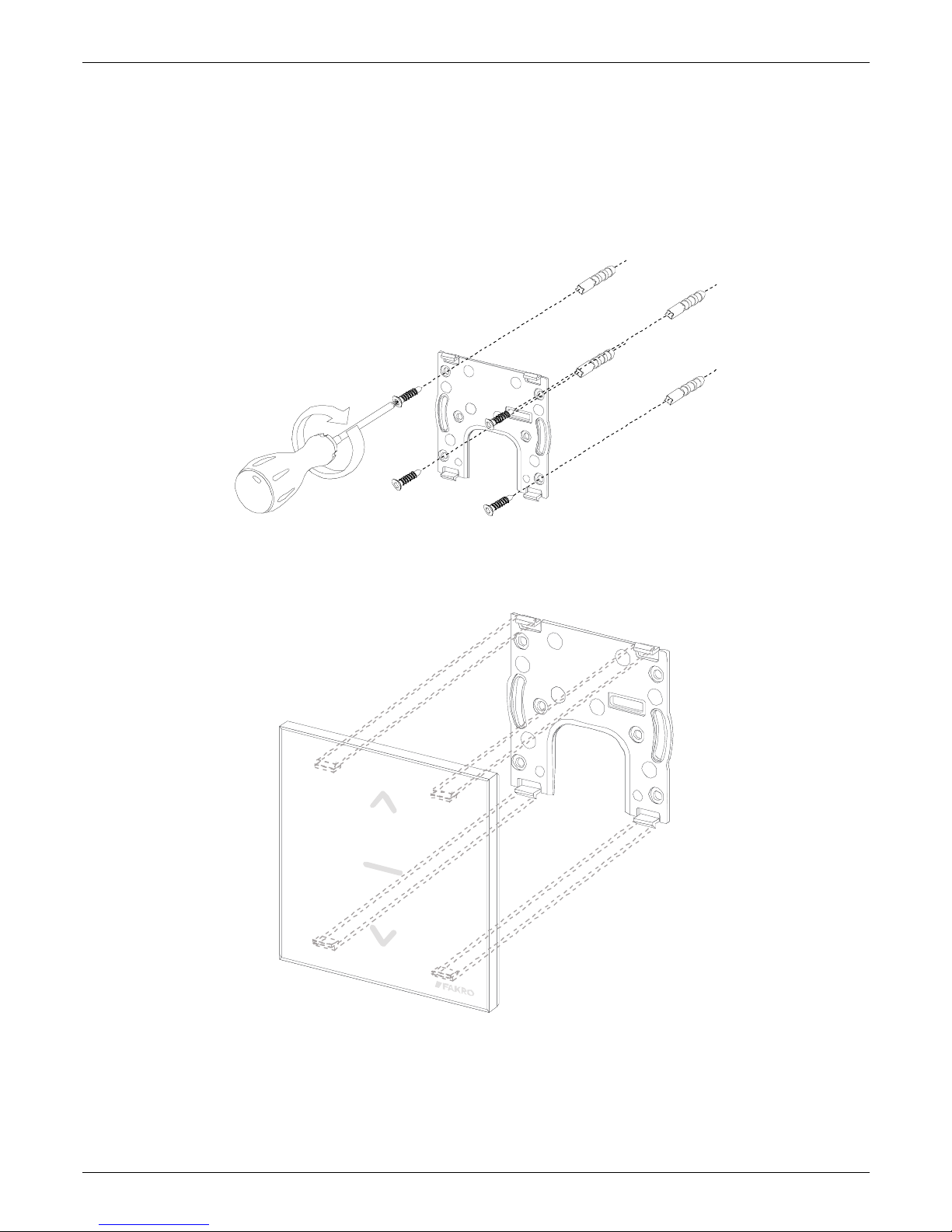
The ZWG1 controller should be attached to the wall or other permanent building element by means
of four screws driven into cylindrical plugs placed in the openings drilled earlier in the wall. Mounting bracket
is also designed for mounting in a standard electric can.
1. Fix the holder to the wall using included screws driven into wall plugs placed in the drilled openings.
2. Place the ZWG1 controller onto the holder.
11.11.15 NC818 3/16 ©2012, FAKRO

3. Controller programming
In order to operate FAKRO electronic accessories, featuring Z-Wave system, by means of the
ZWG1 controller, it is necessary to:
1. Add the device to the “Z-Wave” network (INCLUDE function) – see section 3.1
and
2. Associate the device with a selected pair of buttons on the controller with which user wishes to operate
the device (ASSOCIATE function) – see section 3.2.
In one “Z-Wave” network, there can be included a maximum of 232 devices, i.e. controllers, electronic
accessories for FAKRO roof windows as well as other electronic devices.
Note !!! Any device which is physically removed from the network (e.g. damaged) should be deleted from the
memory of the controller (PRIMARY, SECONDARY), that is first deleted from the pair of buttons (section
3.4) and then removed from the network (section 3.5). The correct implementation of the procedures is to
ensure optimal communication between devices. Unplugging the device without removing it from the controller
memory will result in a prolonged reaction time to commands and faster depletion of the controller battery. If it
is necessary to remove the damaged equipment, whose removal from the controller memory is not possible, it is
desirable to reconfigure the whole network (all devices). Start a new network configuration from restoring the
controller to the factory settings (DEFAULT function), then call the EXCLUDE function of devices working
correctly and continue to the section 3, "Controller Programming".
Note !!! Moving the device within the network (e.g. socket module) it is recommended to delete it from the
controller memory (delete it from the pair of buttons first (section 3.4) and then remove from the network
(section 3.5) and then add it again after installation in new place of work.
11.11.15 NC818 4/16 ©2012, FAKRO
3.1. Adding device to network (INCLUDE function)
Adding a device to the “Z-Wave” network is possible only via “PRIMARY” controller (every
single brand new controller is set as primary controller by default). In each network, there is always only one
primary controller and any other added to it is identified as “SECONDARY”. The procedure of device adding
to the network is presented in Figure 2.
*) Programming error can be caused by:
• no button being pressed within 10 seconds from controller signaling its readiness for adding a new
device to the network;
• long distance between controller and device being added;
• the device already belonging to other network. It is necessary to use EXCLUDE function and repeat the
procedure of device adding to the network.
11.11.15 NC818 5/16 ©2012, FAKRO
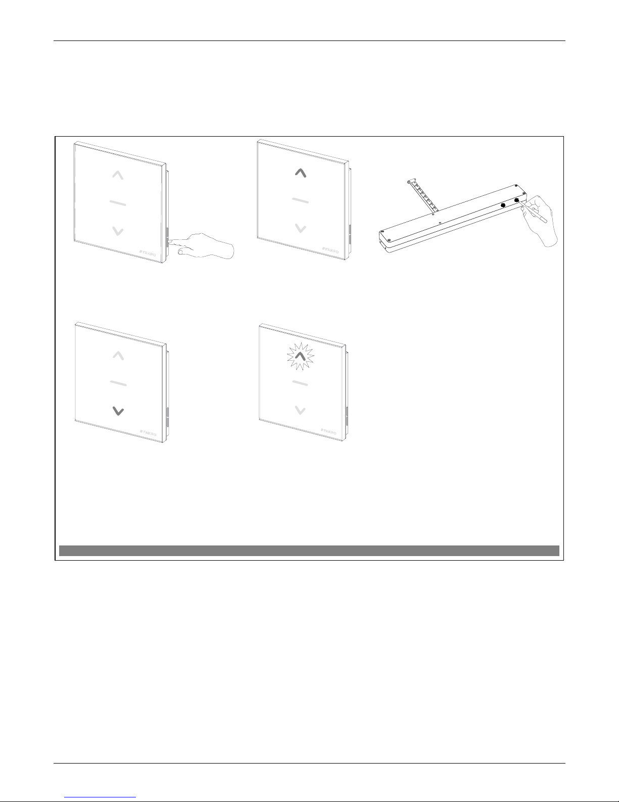
Figure 2: Adding device to Z-Wave network
3. Press “P” button on the device
and hold it for 0.5 sec. (see
Installation Manual).
4. The controller is signalizing that the
device has been successfully added to
the network (button lights up for 2-3
sec. as presented in the drawing).
1. Press “In/Ex” button once
5*. Programming error – button flashing for
2-3 sec. as presented in the drawing.
2. The controller is signalizing its
readiness for adding a new device to
the network (button lights up for 10
sec. as presented in the drawing).
x1
x1
Note!!! In the newer controller version, interrupting any procedure is possible by pressing the “IN/EX” button. In the
older version, it is necessary to wait 10 seconds until the error is signalled by the controller or reset it by removing the
batteries.
 Loading...