

Page 1
FAI DETMULTI
Instruction Manual
Read this instruction manual thoroughly
before use and retain for future reference.
Page 2

2
This instrument is guaranteed to be free from
defects in material and workmanship for a period
of one year. The guarantee does not cover
product failure due to misuse, negligence or fair
wear and tear. In the case of electrical products
used for hire, the guarantee period is restricted
to three months. This guarantee does not cover
expendable items such as batteries or fuses.
Warranty
Safety Information
Electrical Symbols
This digital multimeter has been designed
according to IEC-1010 concerning electronic
measuring instruments with a measurement
category II (CAT II 600V) and pollution degree 2.
AC (Alternating Current)
DC (Direct Current)
Important safety information. Refer to Manual.
Dangerous voltage may be present.
Earth ground
Fuse
Conforms to European Union directives
The equipment is protected throughout by
double or reinforced insulation
Page 3
3
Warning
To avoid possible electric shock or personal
injury, follow these guidelines:
Do not use the meter if it is damaged.
Before you use the meter, inspect the case.
Pay particular attention to the insulation
surrounding the connectors.
Inspect the test leads for damaged insulation
or exposed metal. Check the test leads for
continuity.
Replace damaged test leads before you use
the meter.
Do not use the meter if it appears to operate in
unusual manner as its safety features may be
impaired. If in doubt, have the meter serviced.
Do not operate the meter around explosive
gas, vapour or dust.
Do not apply more than the rated voltage, as
marked on the meter, between terminals or
between any terminal and earth ground.
Before use, verify the meter's operation by
measuring a known voltage.
Do not operate this meter in a manner not
specified by the manufacturer as the protection
provided by the equipment may be impaired.
Page 4
4
When servicing the meter, use only specified
replacement parts.
Use with caution when working above 30V ac
rms, 42V peak, or 60V dc. Such voltages pose
a shock hazard. USE EXTREME CAUTION
when working with high voltages.
When using the probes, keep your fingers
behind the finger guards on the probes.
Connect the common test lead before you
connect the live test lead. When you disconnect
test leads, disconnect the live test lead first.
Remove the test leads from the meter before
you open the case or the cover.
Do not operate the meter with the back cover
or portions of the case removed or loosened.
To avoid false readings, which could lead to
possible electric shock or personal injury,
replace the batteries as soon as the low
battery indicator ( ) appears.
CAUTION - When an input terminal is connected
to a dangerous live source it is to be noted that
a shock potential equivalent to the live source is
present at all other terminals. USE EXTREME
CAUTION when working with high voltages.
When measuring a current, turn off the circuit
power before connecting the meter in the
circuit. Remember to place the meter in series
with the circuit.
Page 5
5
CAT II - Measurement Category II is for
measurements performed on circuits directly
connected to low voltage installation.
(Examples are measurements on household
appliances, portable tools and similar
equipment.)
Do not use the meter for measurements
within Measurement Categories III and IV.
Caution
To avoid possible damage to the meter or to
the equipment under test, follow these
guidelines:
Disconnect circuit power and discharge all
high-voltage capacitors before testing
resistance, continuity, diodes, or capacitance.
Use the correct terminals, function, and range
for your measurements.
Before measuring current, check the meter's
fuse and turn the power OFF to the circuit
before connecting the meter to the circuit.
Before rotating the range switch to change
functions, disconnect test leads from the
circuit under test.
Remove test leads from the meter before
opening the meter case.
Page 6

6
Before opening the case, always disconnect
the test leads from all live circuits.
To continue protection against fire, replace
fuse only with the specified voltage and
current ratings: F250mA/250V (Fast Blown)
Φ 5 x 20
Periodically wipe the case with a damp cloth
and mild detergent. Do not use abrasives or
solvents.
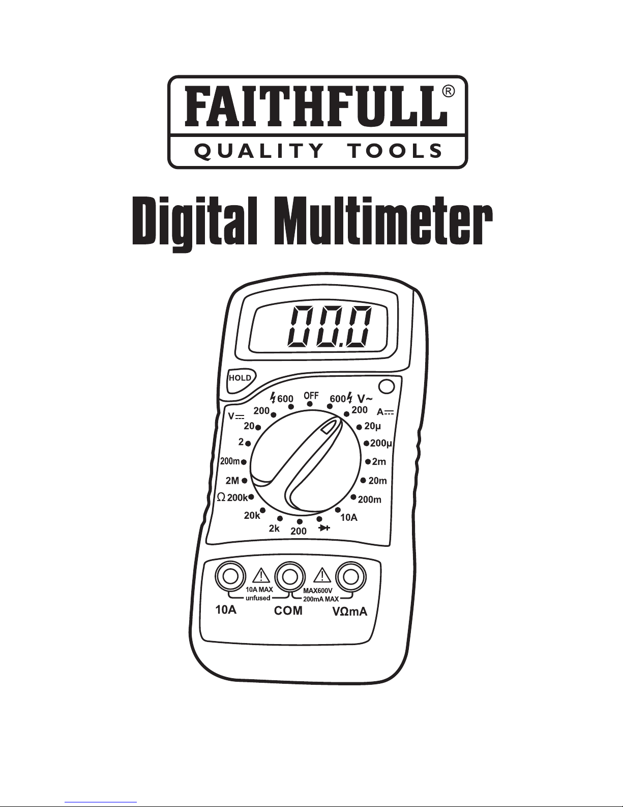
FAI DETMULTI is a handheld 3½-digit LCD
digital multimeter with the advantages of
precision reading and stable performance, and
can be used for the measurement of DC voltage,
AC voltage, DC current, resistance, diode and
continuity.
Maintenance
Introduction
Page 7
7
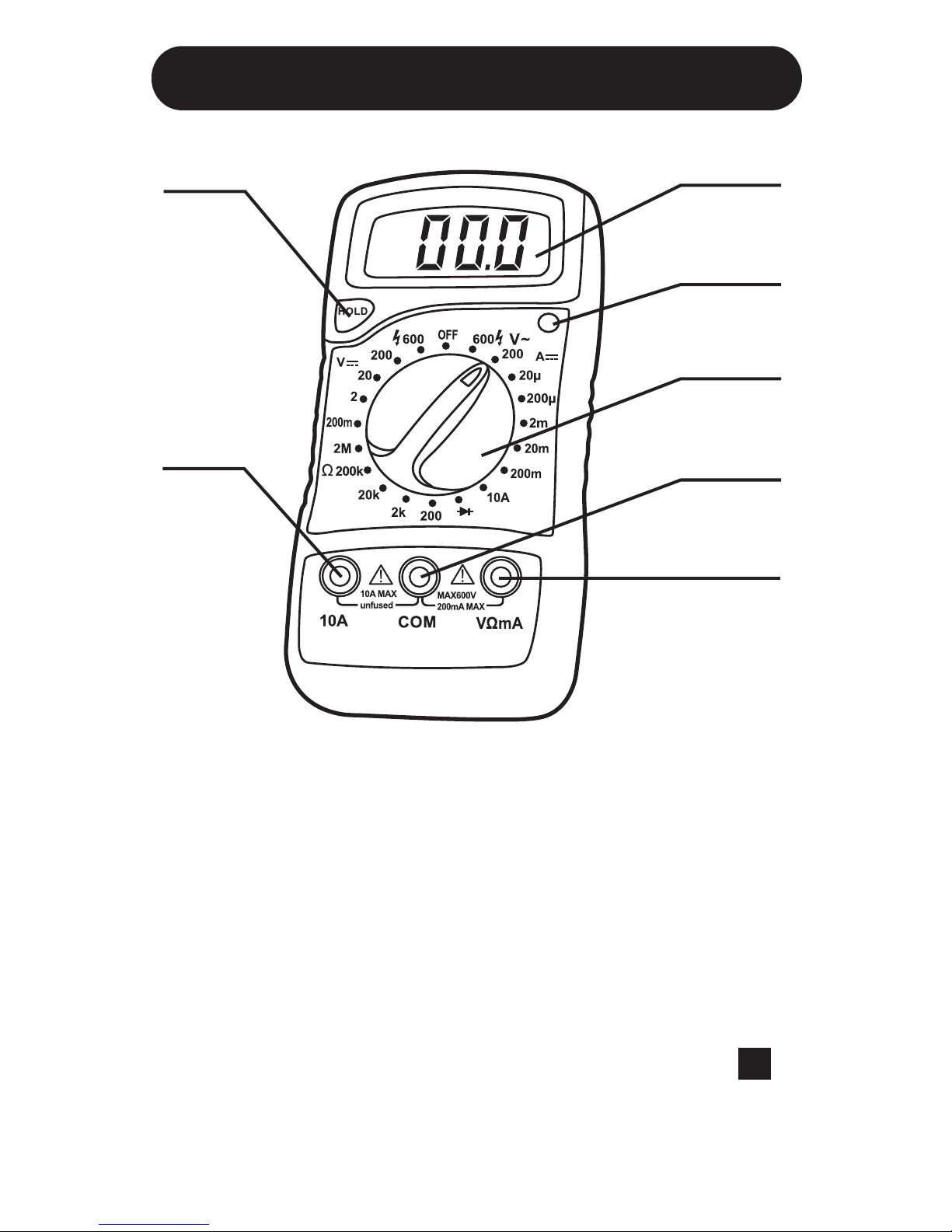
Front Panel
1. Display 3½ digit, 7 segment, 15mm high LCD.
2. Back light switch Press to illuminate the LED
display, auto switch off after approximately
7 seconds.
3. Rotary switch Used to turn the meter on and
off and select the required function and ranges.
4. Hold button When this button is pushed, the
display will keep the last reading and the “ H ”
symbol will appear in the LCD until the button
is pushed again.
1
2
3
6
7
4
5
Page 8

8
General Specifications
Display: 3½-digit LCD, Max reading 1999
Measuring method: Dual-slope integration A/D
converter
Automatic polarity indication, " - " displayed for
negative polarity
Automatic over-range indication with
figure "1" displayed.
Auto power-off
Operating temperature: 0°C~40°C (32°F~104°F)
Storage temperature: -10°C~50°C (14°F~122°F)
Low battery indication: Symbol " " displayed
on the upper left side of the LCD.
Dimensions: 138 x 69 x 31mm
Weight: approx. 170g (including battery)
5. “10A” jack Plug in connector for Red test
lead when performing 10A measurement.
6. “COM” jack Plug in connector for Black
(negative) test lead.
7. “VΩmA” jack Plug in connector for Red
(positive) test lead for voltage, resistance and
current (except 10A) measurements.
Page 9
9
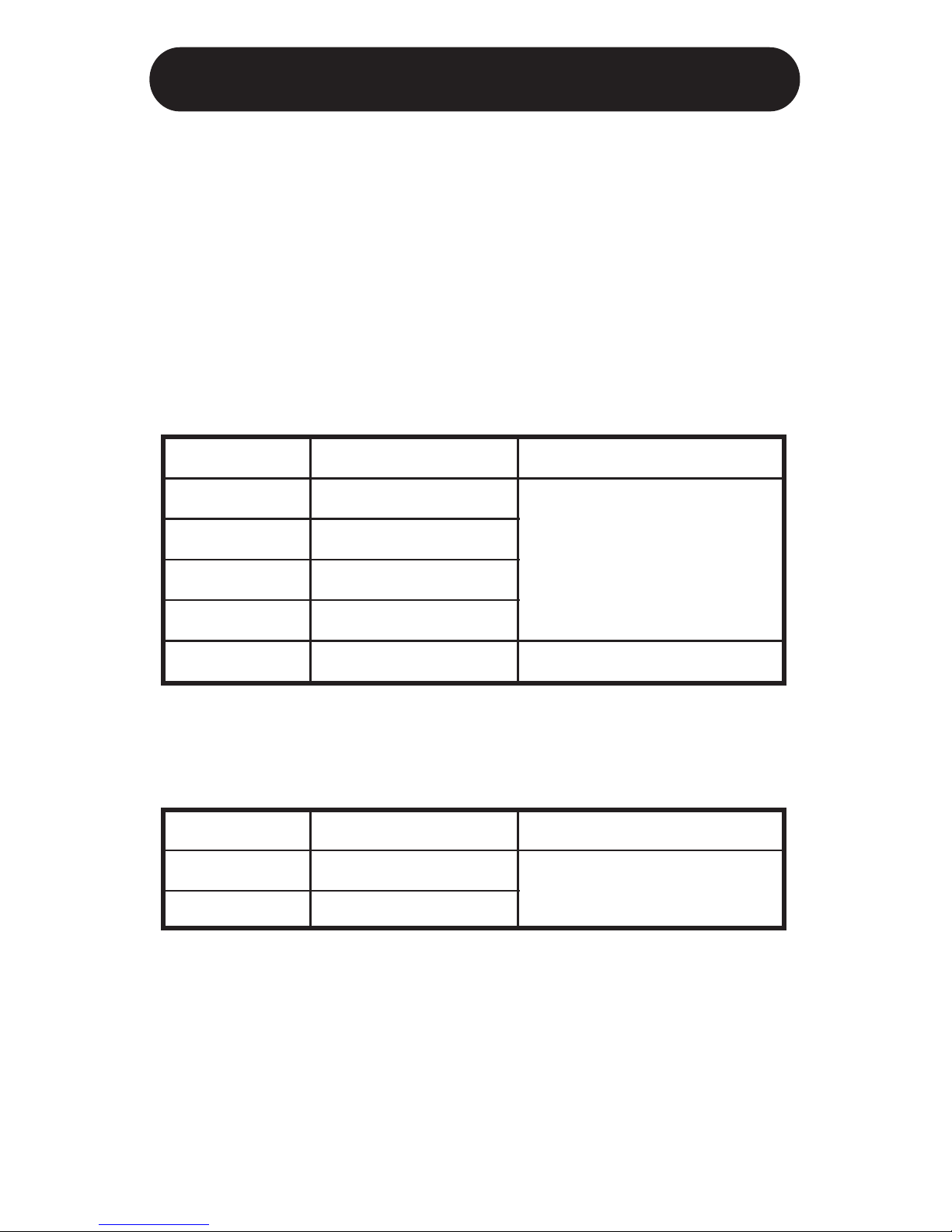
DC VOLTAGE
Specifications
Accuracy is specified for a period of 1 year after
calibration and at 18°C ~ 28°C with relative
humidity up to 75%
Accuracy specifications take the form of:
±[(% of Reading)+(Number of Least Significant Digits)]
ACCURACY
±(0.8%+5)
±(1.0%+5)
RANGE
200mV
2V
20V
200V
600V
RESOLUTION
100µV
1mV
10mV
100mV
1V
ACCURACY
±(1.2%+10)
RANGE
200V
600V
RESOLUTION
100mV
1V
Input impedance 1MΩ
AC VOLTAGE
Input impedance: about 500KΩ
Response: average, calibrated in RMS of sine wave.
Frequency Response:40 - 400Hz
Page 10
10
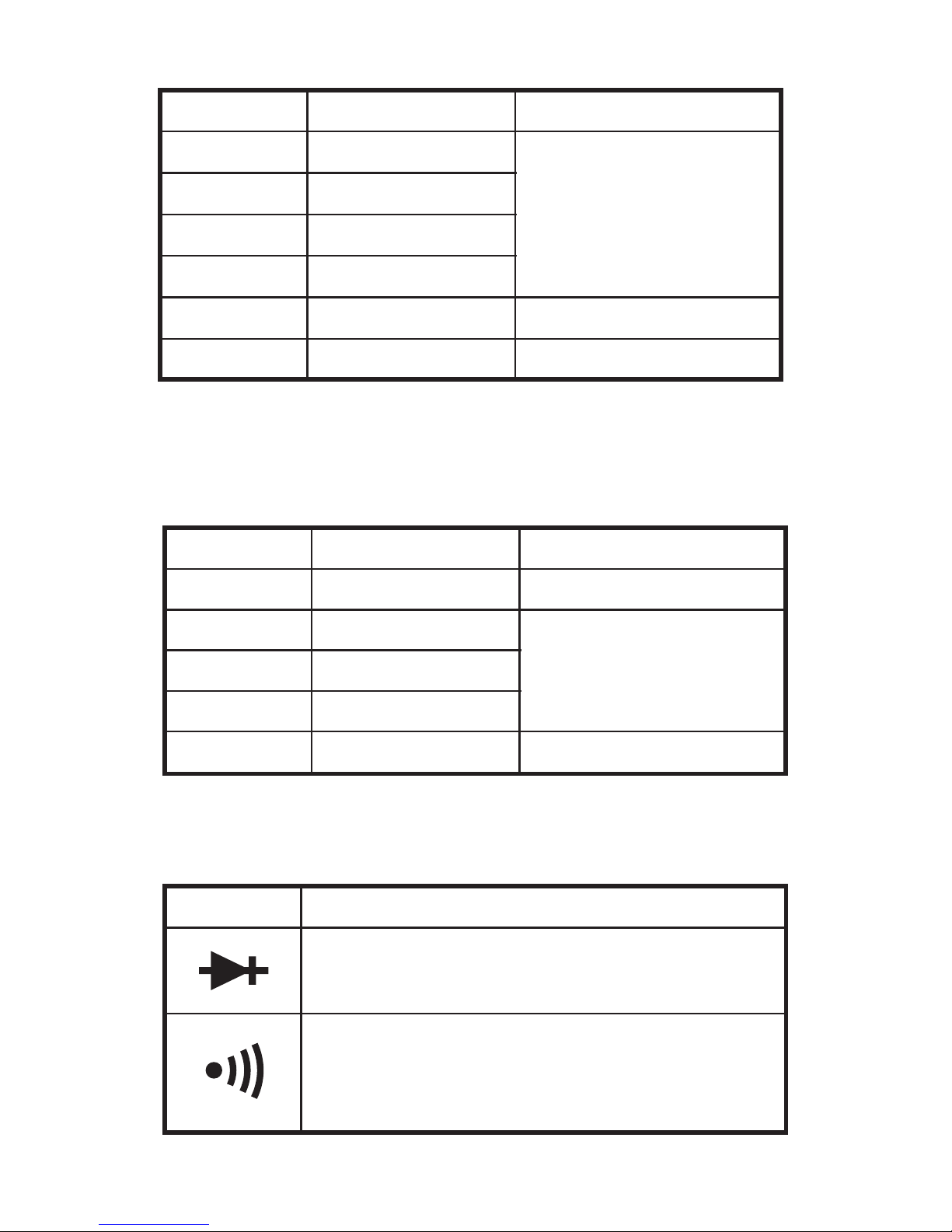
RESISTANCE
Maximum open circuit voltage: 3.2V
DIODE & AUDIBLE CONTINUITY
ACCURACY
±(1.2%+5)
±(1.0%+5)
±(1.2%+5)
RANGE
200Ω
2kΩ
20kΩ
200kΩ
2MΩ
RESOLUTION
0.1Ω
1Ω
10Ω
100Ω
1kΩ
RANGE DESCRIPTION
The approx. forward voltage drop of
the diode will be displayed on the LCD.
If the resistance under measurement
is less than about 50Ω, the built-in
buzzer will sound
ACCURACY
±(1.0%+5)
±(1.2%+5)
±(2.0%+5)
RANGE
20µA
200µA
2mA
20mA
200mA
10A
RESOLUTION
0.01µA
0.1µA
1µA
10µA
100µA
10mA
DC CURRENT
Max. input current: 10A (Can not last for more
than 10 seconds)
Page 11

11
Operating Instructions
DC Voltage Measurement
1. Connect the Red test lead to the "V Ω mA" jack
and the Black test lead to the "COM" jack.
2. Set the Function/Range switch to the desired
range. If the voltage to be measured is not
known beforehand, set the range switch to the
highest range and then turn it down range by
range until satisfactory resolution is obtained.
3. Connect the test leads to the source or circuit
to be measured.
4. Read the voltage value displayed on the LCD
along with the polarity of the Red test lead.
DC Current Measurement
1. Connect the Black test lead to the "COM" jack
and the Red test lead to the "V Ω mA" jack.
(If the current to be measured is between
200mA and 10A, remove the Red test lead to
the 10A jack instead.)
(For "10A" jack, the max. permitted test
duration is 10 seconds, interval is 15 minutes.)
Page 12

12
2. Set the Function/Range switch to the desired
range. If the current to be measured is not
known beforehand, set the range switch to the
highest range and then turn it down range by
range until satisfactory resolution is obtained.
3. Open the circuit in which the current is to be
measured, and connect the test leads in series
with the circuit.
4. Read the current value displayed on the LCD
along with the polarity of the Red test lead.
AC Voltage Measurement
1. Connect the Red test lead to the "V Ω mA" jack
and the Black test lead to the "COM" jack.
2. Set the Function/Range switch to the desired
V~ range. If the voltage to be measured is not
known beforehand, set the range switch to the
highest range and then turn it down range by
range until satisfactory resolution is obtained.
3. Connect the test leads to the source or load to
be measured.
4. Read the voltage value displayed on the LCD.
Page 13
13
Resistance Measurement
1. Connect the Red test lead to the "V Ω mA" jack
and the Black test lead to the "COM" jack.
2. Set the Function/Range switch to the desired Ω
range.
3. Connect the test leads to the resistor to be
measured and read the value displayed on the
LCD.
Note
While measuring resistance about 1MΩ and above,
the meter may take a few seconds to stabilize.
This is normal for high resistance readings.
Diode Test
1. Connect the Red test lead to the "V Ω mA" jack
and the Black test lead to the "COM" jack.
(The polarity of the red test lead is positive "+".)
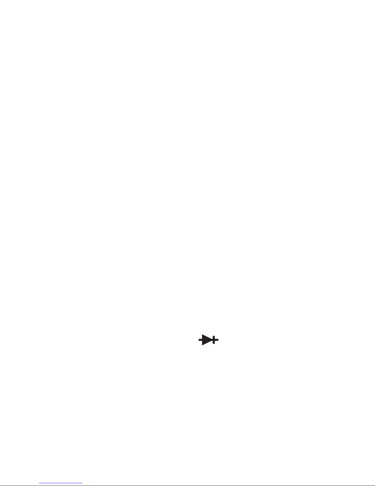
2. Set the rotary switch to " " range.
3. Connect the Red test lead to the anode of the
diode to be tested and the Black test lead to the
cathode of the diode. The approximate forward
voltage drop of the diode will be displayed on
the LCD. If the connection is reversed, only
figure "1" will be shown.
Page 14

14
Audible Continuity Test
1. Connect the Red test lead to the "V Ω mA" jack
and the Black test lead to the "COM" jack.
2. Set the Function/Range switch to " " range.
3. Connect the test leads to the two terminals of
the circuit to be tested. If the resistance is less
than about 50Ω, the built-in buzzer will sound.
Test Signal Output
1. Set the Function/Range
switch to the " " range.
2. A test signal (50Hz, about 2.5Vp-p) is output
between "VΩmA" and "COM" jack. When the
test signal is connected to a circuit, an
additional blocking capacitor should be used.
Page 15

15
Battery & Fuse Replacement
If " " appears on the LCD, it indicates that the
battery should be replaced. To replace the battery,
open the case and remove the depleted battery,
replace with a new one of the same type (9V
battery, 6F22 or equivalent), then close the case.
Depleted batteries should be disposed of at your
local recycling facility.
The fuse rarely needs to be replaced and is blown
generally as a result of the operator's error. To
replace the fuse, open the case, replace the blown
fuse with a new one of the same rating, then close
the case.
The meter uses one fuse: 259mA/250V,
Fast
Φ 5x20mm
Page 16
16
1. This manual is subject to change without notice.
2.
Faithfull tools take no responsibility for any
personal injury, loss or damage caused by the
impropriate or misuse of this product.
3. The contents of this manual can not be used
as the reason to use the meter for any other
special application.
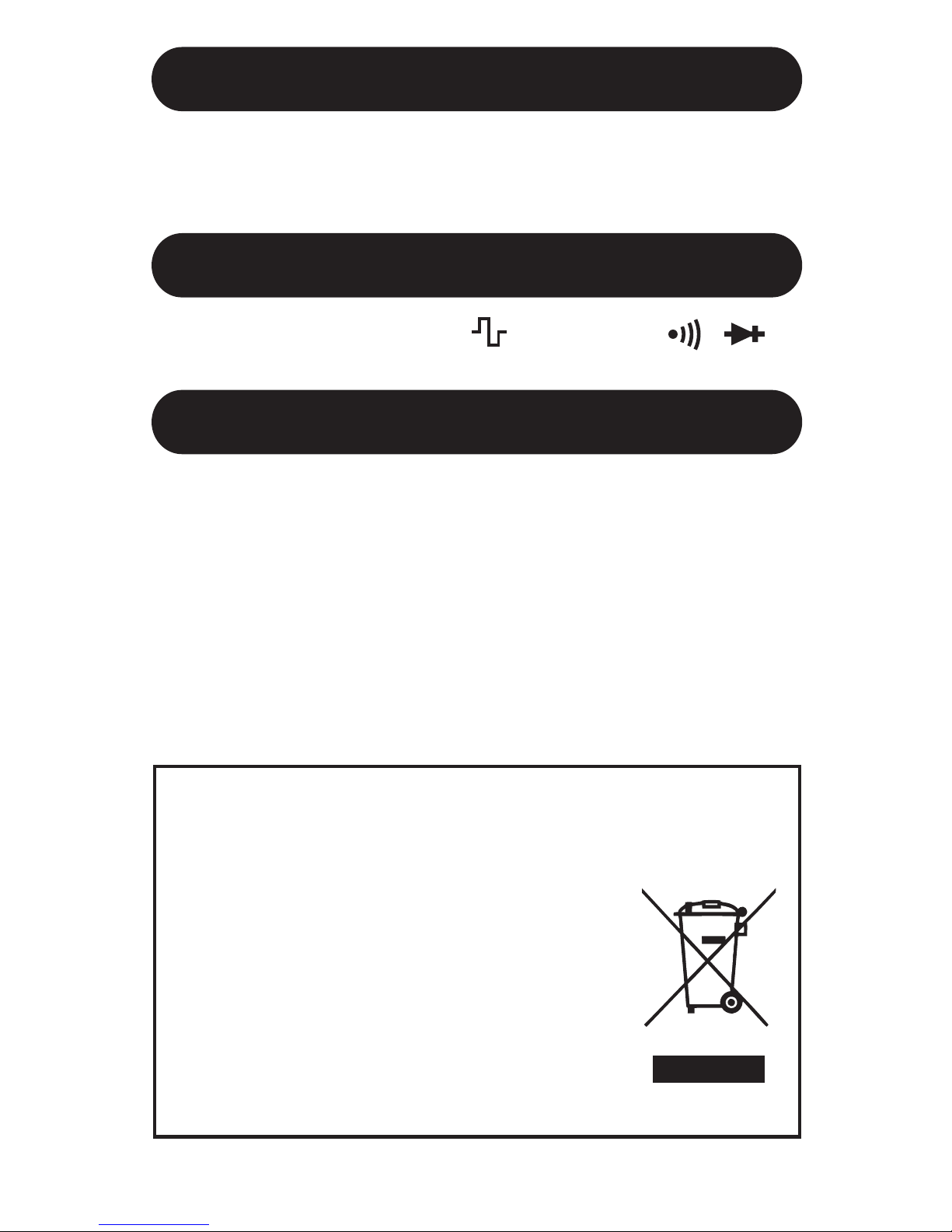
DISPOSAL OF THIS PRODUCT
Dear Customer,
If you at some point intend to dispose of
this article, then please keep in mind that
many of its components consist of
valuable materials, which can be
recycled.
Please do not dispose of it in the rubbish
bin, but check with your local council for
recycling facilities in your area.
Accessories
Functions
Note
Manual: 1 copy
Test Lead: 1 pair
OHM, DCA, ACV, DCV, , Backlight, ,
 Loading...