

Page 1
INSTRUCTION MANUAL
H6635 / 42276
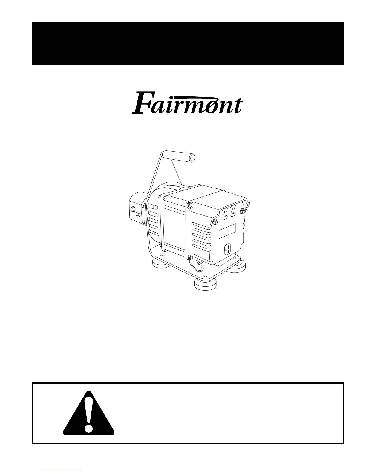
Portable Alternator
99916096 REV 7 © 2006 Greenlee Textron Inc. 6/06
Read and understand all of the instructions and
safety information in this manual before operating
or servicing this tool.
Page 2
H6635 / 42276 Portable Alternator
Table of Contents
Description ..................................................................... 2
Important Safety Instructions ...................................... 3-4
Identification ...................................................................5
Specifications
Alternator ................................................................... 6
Hydraulic Power Source .........................................6-7
Recommended Hydraulic Fluids ................................ 7
Hoses and Fittings ..................................................... 8
Unit / Hose Connections ............................................ 8
Operation .................................................................. 9-10
Maintenance............................................................ 11-12
Troubleshooting ........................................................... 13
Disassembly ................................................................. 14
Inspection ..................................................................... 15
Assembly...................................................................... 15
Illustration and Parts ............................................... 16-17
Accessories (Optional) .................................................18
Description
Safety
Safety is essential in the use and maintenance of
Fairmont tools and equipment. This instruction manual
and any markings on the tool provide information for
avoiding hazards and unsafe practices related to the use
of this tool. Observe all of the safety information provided.
Purpose
This instruction manual is intended to familiarize
personnel with the safe operation and maintenance
procedures for the following Fairmont tool:
H6635/42276 Portable Alternator
Keep this manual available to all personnel.
Replacement manuals are available upon request
at no charge.
The H6635/42276 Portable Alternator provides instant
electric power for lighting, heaters and other electrical
equipment. It is driven by a hydraulic gear motor and is
able to operate from hydraulic systems with flow rates
from 30-45 l/min (8-12 gpm). The alternator, a 60-cycle,
single-phase unit, is capable of delivering up to 3500
watts of electrical power through its 120 and 240 volt AC
outlets.
The 120 volt duplex receptacle is split so that 15 amps
of current may be drawn from either half of the receptacle.
These outlets may be used along with the 240 volt
receptacle provided the alternator is not overloaded.
A maximum of 14.6 amps may be drawn from the 240
volt receptacle provided it is the only receptacle used.
When using the unit, current must be limited to the
ratings on the nameplates of the equipment being
used. If the 240 volt receptacle is used along with the
120 volt receptacles, the total load drawn must not
exceed the equipment’s nameplate ratings.
Outlet 1 120 Volts x Amps Draw = Watts #1
Outlet 2 120 Volts x Amps Draw = Watts #2
Outlet 3 240 Volts x Amps Draw = Watts #3
Outlet 4 240 Volts x Amps Draw = Watts #4
Total of all outlets used
must not exceed 3500 watts.
Do not discard this product or throw away!
For recycling information, go to
www.greenlee.com.
All specifications are nominal and may change as design improvements occur. Greenlee Textron Inc. shall not be liable for damages
resulting from misapplication or misuse of its products.
Greenlee / A Textron Company 2 4455 Boeing Dr. • Rockford, IL 61109-2988 USA • 815-397-7070
KEEP THIS MANUAL
Page 3
IMPORTANT SAFETY INFORMATION
SAFETY
ALERT
SYMBOL
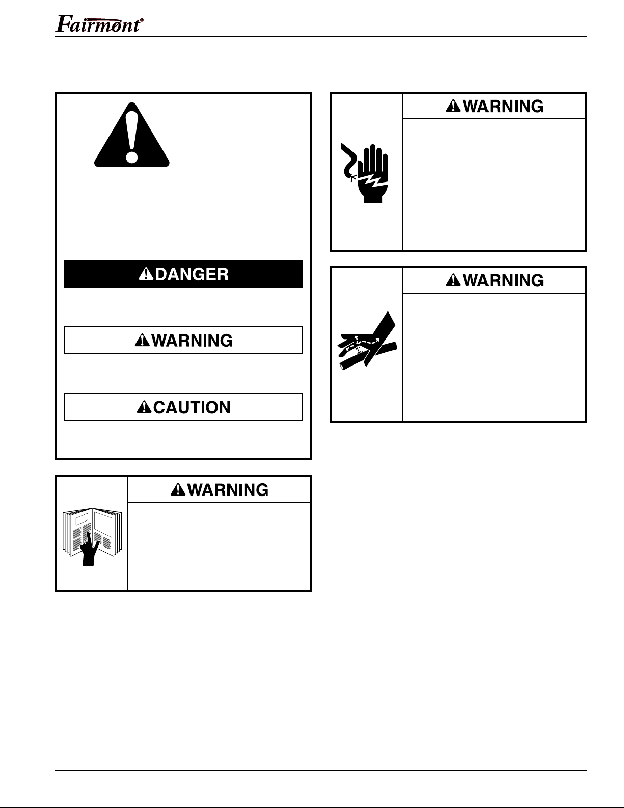
This symbol is used to call your attention to hazards
or unsafe practices which could result in an injury
or property damage. The signal word, defined below,
indicates the severity of the hazard. The message
after the signal word provides information for preventing or avoiding the hazard.
H6635 / 42276 Portable Alternator
Electrical shock hazard:
• This unit generates up to 240
volts. Contact with live circuits can
result in severe injury or death.
• Do not operate or store the unit in
wet or damp locations.
• Keep the unit clean and dry.
• Do not connect any electrical
device with a damaged cord.
Immediate hazards which, if not avoided, WILL result
in severe injury or death.
Hazards which, if not avoided, COULD result in
severe injury or death.
Hazards or unsafe practices which, if not avoided,
MAY result in injury or property damage.
Read and understand all of the
instructions and safety information
in this manual before operating or
servicing this tool.
Failure to observe this warning could
result in severe injury or death.
Skin injection hazard:
High pressure oil easily punctures
skin causing serious injury, gangrene
or death. If injured seek medical help
immediately to remove oil.
Do not use fingers or hands to check
for leaks.
Depressurize hydraulic system
before servicing.
Greenlee / A Textron Company 3 4455 Boeing Dr. • Rockford, IL 61109-2988 USA • 815-397-7070
Page 4
H6635 / 42276 Portable Alternator
IMPORTANT SAFETY INFORMATION
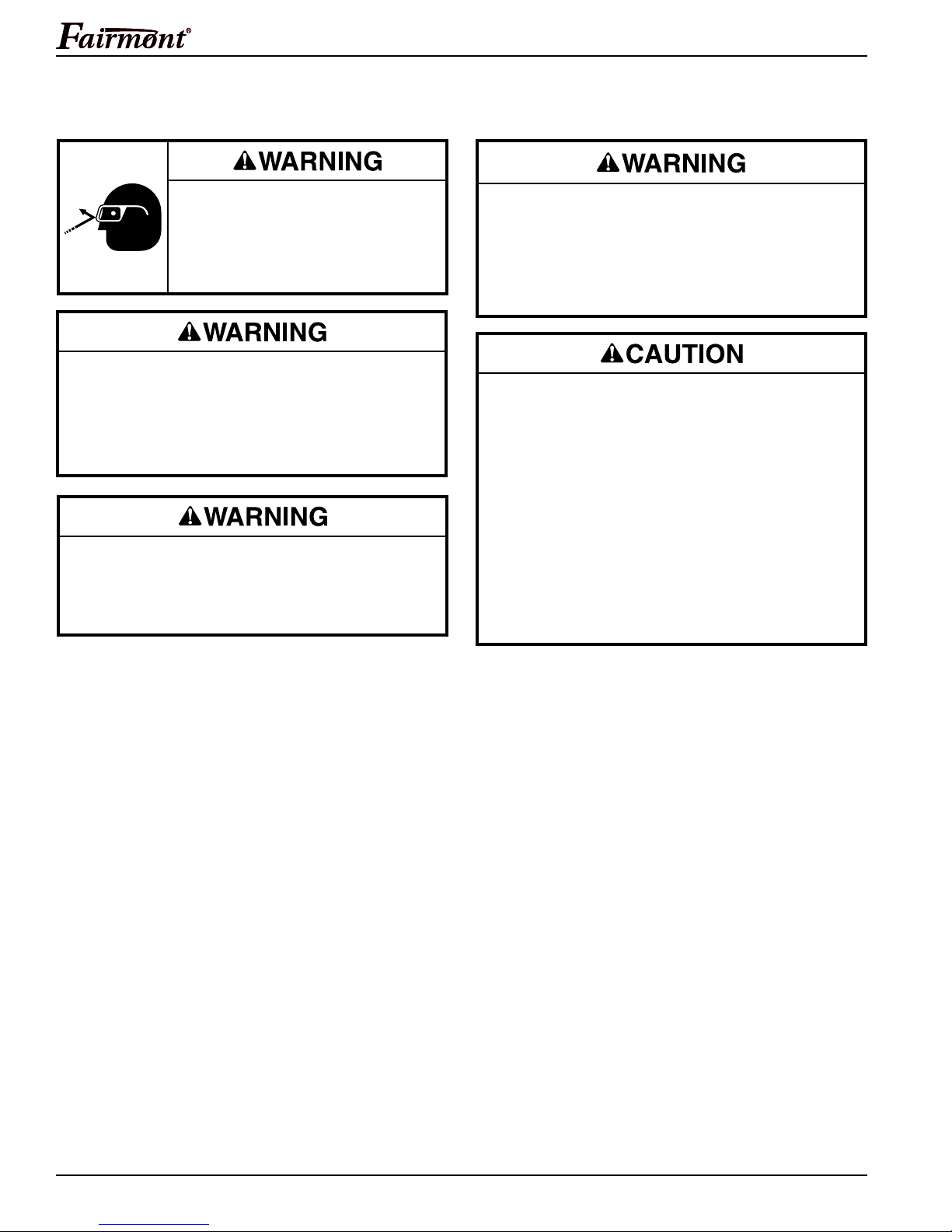
Wear eye protection when operating
or servicing this tool.
Failure to wear eye protection could
result in serious eye injury from
flying debris or hydraulic oil.
Do not inspect, adjust or clean tool when it is
connected to a power source. Accidental startup
can result in serious injury.
Failure to observe these warnings could result in
severe injury or death.
Do not disconnect tool, hoses or fittings while the
power unit is running or if the hydraulic fluid is hot.
Exposure to hot hydraulic fluid can cause serious
burns.
Do not reverse hydraulic flow. Operation with
hydraulic flow reversed can cause tool malfunction.
Always connect supply (pressure) hose and return
(tank) hose to proper tool ports.
Failure to observe this warning could result in
severe injury or death.
• Do not exceed the maximum electrical load.
Overloading will damage the unit.
• Keep the ventilation slots clean and free of debris.
Blocked ventilation slots will cause overheating
and damage the unit.
• Use this tool for manufacturer’s intended purpose
only. Use other than that which is described in this
manual can result in injury or property damage.
• Inspect hydraulic hoses and couplings every
operating day. Repair or replace if leakage,
cracking, wear or damage is evident. Damaged
hoses or coupling can fail resulting in injury or
property damage.
Greenlee / A Textron Company 4 4455 Boeing Dr. • Rockford, IL 61109-2988 USA • 815-397-7070
Page 5
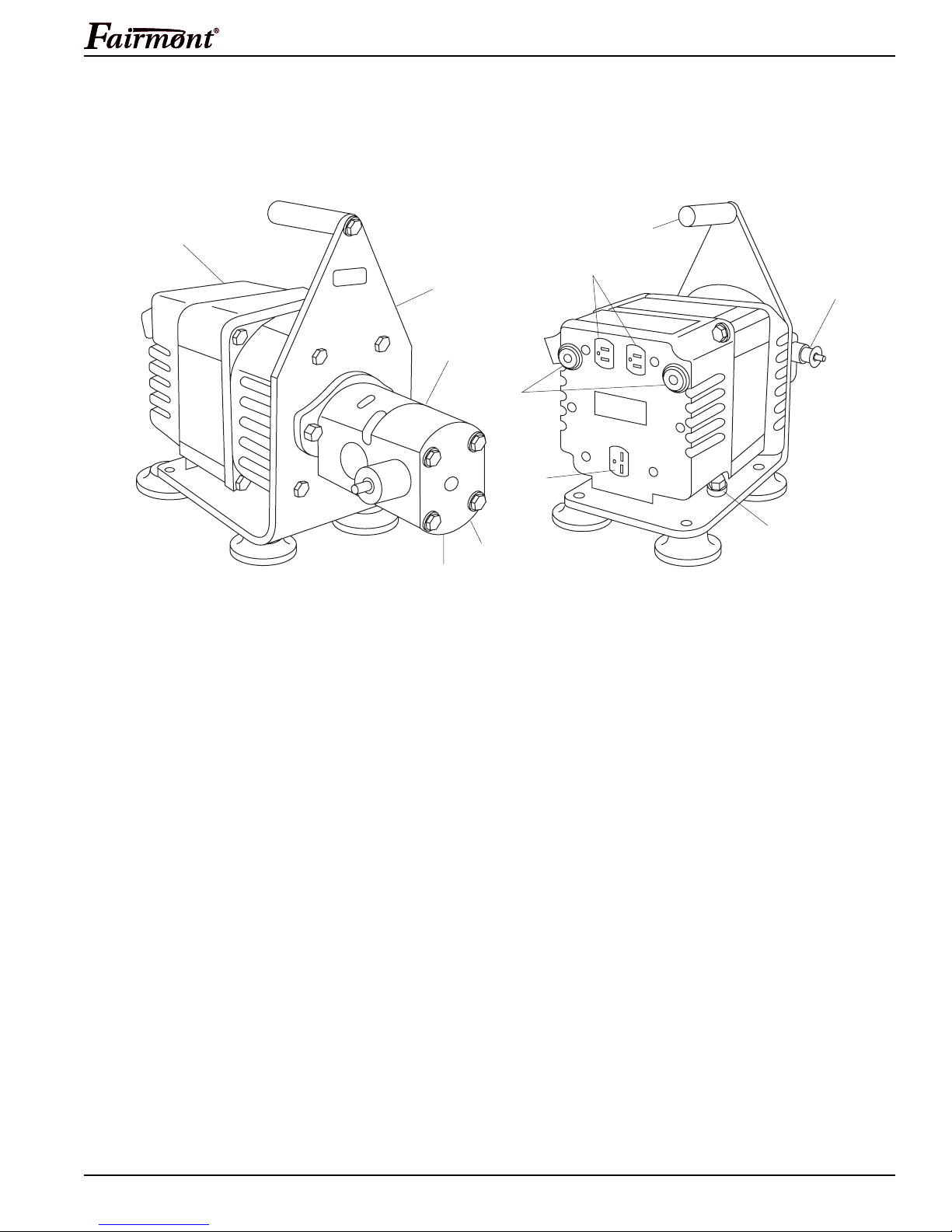
Identification
H6635 / 42276 Portable Alternator
3
4
2
8
6
5
9
10
1
11
7
H6635/42276 Portable Alternator
1. Carrying Handle 7. Ground Lug
2. Mounting Plate 8. Hydraulic Motor
3. Alternator Unit 9. Pressure Port “P”
4. 120 Volt Receptacles 10. Return Port “T”
5. 240 Volt Receptacle 11. Flow Control Cartridge
6. Circuit Breakers
(Do Not Adjust)
Greenlee / A Textron Company 5 4455 Boeing Dr. • Rockford, IL 61109-2988 USA • 815-397-7070
Page 6
Specifications
Alternator
Mass/Weight .............................................................................. 28.6 kg (63 lb)
Height ................................................................................... 36.8 cm (14.00 in)
Length .................................................................................. 41.9 cm (16.50 in)
Width ....................................................................................... 21.6 cm (8.50 in)
Power ............................................................................................... 3500 Watts
Voltage .......................................................................................... 120/240 VAC
Frequency ................................................................................................. 60 Hz
Current ...................................................................................... 29.2/14.6 Amps
Phase ....................................................................................................... Single
Insulation Class ................................................................................................ F
Ambient Temperature ................................................................ 40° C (104° F)
Pressure Port ......................................................................... 1/2 NPTF Female
Return Port ............................................................................. 1/2 NPTF Female
H6635 / 42276 Portable Alternator
Hydraulic Power Source
• Power source flow must be at least 30.3 l/min (8 gpm) and must not
exceed 45.4 l/min (12 gpm).
• Limit relief pressure to 172.4 bar (2500 psi).
Failure to observe these warnings could result in over-pressurizing the
system causing severe injury to operator or bystanders.
Type of Hydraulic System ................................................ Open- or Closed-Center
Filtration ..................................................................................10 micron (nominal)
Flow
Minimum ............................................................................ 30.3 l/min (8 gpm)
Maximum ......................................................................... 45.4 l/min (12 gpm)
Pressure Relief Setting ......................................................... 172.4 bar (2500 psi)
Back Pressure (maximum)* ...................................................... 13.8 bar (200 psi)
* 13.8 bar (200 psi) is the maximum agreed standard back pressure for the
Hydraulic Tool Manufacturers Association (HTMA). Fairmont tools will operate
satisfactorily at this standard.
1. Maximum hydraulic fluid temperature must not exceed 60°C (140°F).
A sufficient oil cooling capacity is needed to limit the hydraulic fluid
temperature.
2. Maximum hydraulic flow must be at least 30.3 l/min (8 gpm) and must not
exceed 45.4 l/min (12 gpm). Install a flow meter in the return line to test the
rate of hydraulic flow before working the tool.
3. Pressure relief valve setting must not exceed 172.4 bar (2500 psi). Locate
the pressure relief valve at your tool’s maximum flow in the supply circuit to
limit excessive hydraulic pressure to the tool.
Greenlee / A Textron Company 6 4455 Boeing Dr. • Rockford, IL 61109-2988 USA • 815-397-7070
Page 7
Specifications (cont’d)
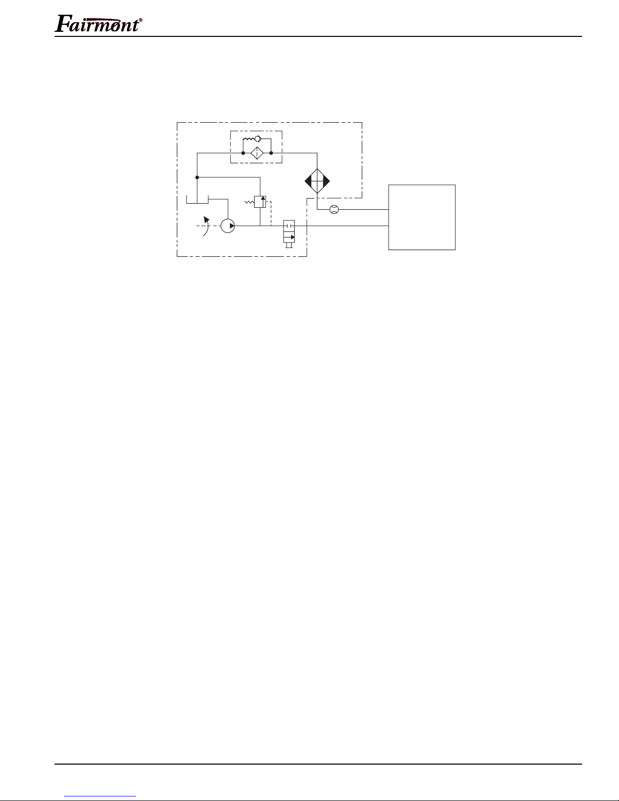
Hydraulic Schematic
FILTER
(10 MICRON)
H6635 / 42276 Portable Alternator
Recommended Hydraulic Fluids
Use any non-detergent, petroleum-based hydraulic fluid which meets the following
specifications or HTMA specifications may be used.
S.U.S.
@ 38°C (100°F) ........................................................................... 140 to 225
@ 99°C (210°F) .........................................................................40 minimum
Flash Point ................................................................... 170°C (340°F) minimum
Pour Point ...................................................................... -34°C (-30°F) minimum
RESERVOIR
PUMP
POWER SOURCE
RELIEF
VALVE
2000 PSI
CONTROL
VALVE
COOLER
FLOW METER
T
P
ALTERNATOR
Greenlee / A Textron Company 7 4455 Boeing Dr. • Rockford, IL 61109-2988 USA • 815-397-7070
Page 8
Specifications (cont’d)
H6635 / 42276 Portable Alternator
Hoses and Fittings
Hoses and fittings used with this tool must comply
with SAE Standard J1273 (See Appendix A)
recommended practice for selection, installation
and maintenance of hose and hose assemblies.
Failure to observe this warning could result in
severe injury.
Hose assemblies and quick connect couplers are
available from Fairmont as accessories. SEE BULLETIN
ON FAIRMONT NO-DRIP COUPLERS AND HOSES.
CONTACT AUTHORIZED FAIRMONT DISTRIBUTOR.
Unit/Hose Connections
• Always stop power source before connecting or
disconnecting tool.
• Do not disconnect hydraulic components, lines
or fittings while hydraulic power source is
running and/or hydraulic fluid is hot. Exposure to
hot hydraulic fluid can cause serious burns.
Failure to observe these warnings could result in
severe injury.
Connecting Hoses (see Figures 1, 2, 3)
Note: Return (tank) hose connection should always
be connected before supply (pressure) hose connection
to prevent pressure buildup inside the unit.
1. Stop the power source.
2. Connect the return (tank) hose from the power
source (port T) to the unit (T port).
3. Connect the supply (pressure) hose from the power
source (port P) to the unit (P port).
Disconnecting Hoses (see Figures 1, 2, 3)
Note: Supply (pressure) hose connection should always
be disconnected before return (tank) hose connection to
prevent pressure buildup inside the tool.
1. Stop the power source.
2. Disconnect the supply (pressure) hose from the
power source (port P) to the unit (P port).
3. Disconnect the return (tank) hose from the power
source (port T) to the unit (T port).
4. To prevent contamination, always install dust
caps over the hydraulic ports of the unit when
disconnected.
Greenlee / A Textron Company 8 4455 Boeing Dr. • Rockford, IL 61109-2988 USA • 815-397-7070
Page 9
Operation
H6635 / 42276 Portable Alternator
Electrical shock hazard:
• This unit generates up to 240
volts. Contact with live circuits can
result in severe injury or death.
• Do not operate or store the unit in
wet or damp locations.
• Keep the unit clean and dry.
• Do not connect any electrical
device with a damaged cord.
Skin injection hazard:
High pressure oil easily punctures
skin causing serious injury, gangrene
or death. If injured seek medical help
immediately to remove oil.
Do not use fingers or hands to check
for leaks.
Depressurize hydraulic system
before servicing.
Do not disconnect tool, hoses or fittings while the
power unit is running or if the hydraulic fluid is hot.
Exposure to hot hydraulic fluid could cause serious
burns.
Do not reverse hydraulic flow. Operation with
hydraulic flow reversed can cause tool malfunction.
Always connect supply (pressure) hose and return
(tank) hose to proper tool ports.
Failure to observe this warning could result in
severe injury or death.
• Do not exceed the maximum electrical load.
Overloading will damage the unit.
• Keep the ventilation slots clean and free of debris.
Blocked ventilation slots will cause overheating
and damage the unit.
• Use this tool for manufacturer’s intended purpose
only. Use other than that which is described in this
manual may result in injury or property damage.
Wear eye protection when operating
or servicing this tool.
Failure to wear eye protection could
result in serious eye injury from
flying debris or hydraulic oil.
Do not inspect, adjust or clean tool when it is
connected to a power source. Accidental startup
can result in serious injury.
Failure to observe these warnings could result in
severe injury or death.
Greenlee / A Textron Company 9 4455 Boeing Dr. • Rockford, IL 61109-2988 USA • 815-397-7070
Page 10
Operation (cont’d)
H6635 / 42276 Portable Alternator
Setup
1. Stop the power source.
2. Disconnect all electrical loads from the alternator.
3. Place alternator in a clean, dry location.
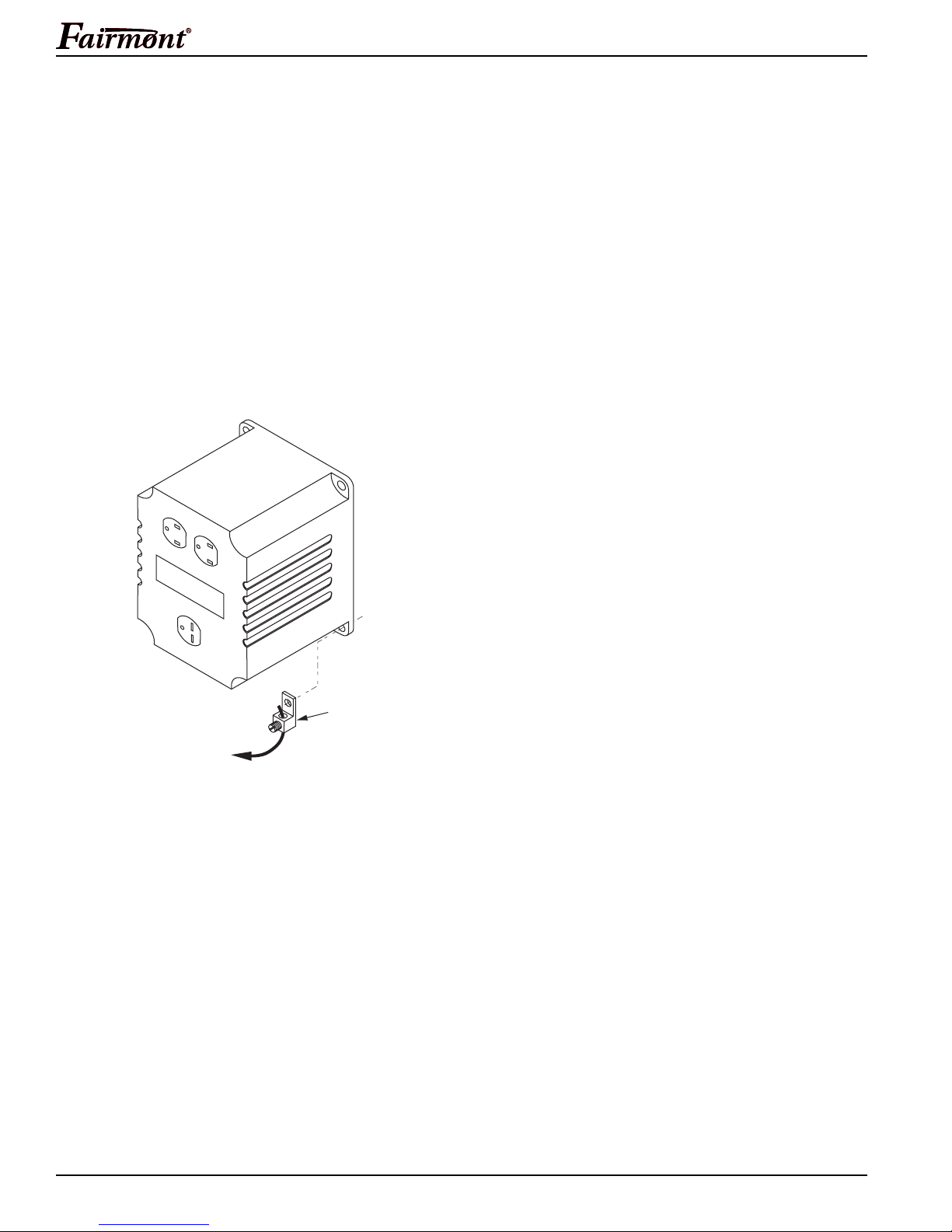
4. To help prevent accidental shock, make sure that
the alternator is grounded. Connect a grounding
wire from the grounding lug on the alternator to a
suitable ground, such as a water pipe, or a copper
rod driven into the ground.
Note: Do not use a pipe carrying combustible
materials as the ground source.
Grounding the Alternator
Operation
Plug in electrical cord of appliance into proper
receptacle. 120 volt appliances utilize the top two
receptacles, and 240 volt appliances utilize the
bottom receptacle.
Receptacles
120 Volt Receptacle:
This duplex receptacle is split so that 15 amps
of current may be drawn from either half of the
receptacle. However, total power must be kept
within the ratings on the nameplates of the
equipment. These receptacles may be used
along with the 240 volt receptacle provided
the alternator is not overloaded.
240 Volt Receptacle:
A maximum of 14.6 amps may be drawn from the
240 volt receptacle provided it is the only receptacle
used. However, current must be limited to the
ratings on the nameplates of the equipment. If the
240 volt receptacle is used along with the 120 volt
receptacles, the total load drawn must not exceed
the equipment’s nameplate ratings.
REMEMBER: VOLTS x AMPS = WATTS
A
TO
GROUND
5. Connect hydraulic hoses from power source to unit.
Start the power source.
Circuit Protection
The receptacles are protected by an AC circuit breaker.
If the alternator is overloaded or an external short circuit
occurs, the circuit breaker will trip. If this occurs, disconnect all electrical loads and try to determine the cause
of the problem before attempting to use the alternator
again. Reset the circuit breaker by pushing the button
on the breaker.
Greenlee / A Textron Company 10 4455 Boeing Dr. • Rockford, IL 61109-2988 USA • 815-397-7070
Page 11
Maintenance
Electrical shock hazard:
• This unit generates up to 240 volts.
Contact with live circuits could
result in severe injury or death.
• Do not operate or store the unit in
wet or damp locations.
• Keep the unit clean and dry.
• Do not connect any electrical
device with a damaged cord.
Skin injection hazard:
High pressure oil easily punctures
skin causing serious injury, gangrene
or death. If injured seek medical help
immediately to remove oil.
Do not use fingers or hands to check
for leaks.
Depressurize hydraulic system
before servicing.
Wear eye protection when operating
or servicing this tool.
Failure to wear eye protection could
result in serious eye injury from
flying debris or hydraulic oil.
Inspect hydraulic hoses and couplings every operating day. Repair or replace if leakage, cracking, wear
or damage is evident. Damaged hoses or coupling
could fail resulting in injury or property damage.
H6635 / 42276 Portable Alternator
The service life of the unit will be maximized by proper
care and maintenance. The maintenance schedule
below is recommended.
Daily:
1. Wipe all unit surfaces clean.
2. Inspect hoses and fittings for signs of leaks, cracks,
wear, or damage. Replace if necessary.
3. Inspect housing of alternator for cracks or damage.
Replace if necessary.
4. Check hydraulic reservoir level. Fill to correct level
if low.
5. Install dust caps when unit is disconnected.
Monthly:
1. Perform a detailed inspection of the system hoses
and fittings as described in publication 99930323,
SAE J1273 (Hose and Hose Assemblies).
2. Change hydraulic system filter.
Semi-Annually:
Drain the hydraulic system. Replace filter and fluid.
Annually:
Inspect the brushes in the alternator for wear, chips, and
cracks. Replace brushes if they are chipped, cracked, or
worn to 7 mm (1/4").
Note: Replace brushes (FOR004494) as a set only.
Other manufacturers’ brushes may appear identical, but
may have completely different mechanical and electrical
characteristics.
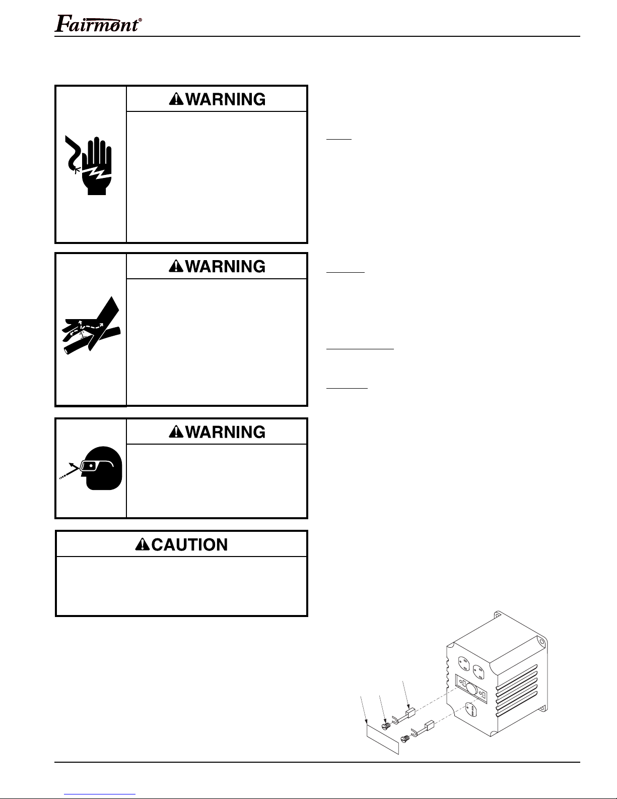
Brush Inspection
1. Remove cover plate (A).
2. Loosen brush mounting screws (B).
3. Slide brushes (C) from holders.
4. Replace brushes (C), if worn to 7 mm (1/4") or if
chipped or cracked.
5. Install cover plate (A). Do not overtighten screws.
Brush Inspection
Greenlee / A Textron Company 11 4455 Boeing Dr. • Rockford, IL 61109-2988 USA • 815-397-7070
C
B
A
Page 12
Maintenance (cont’d)
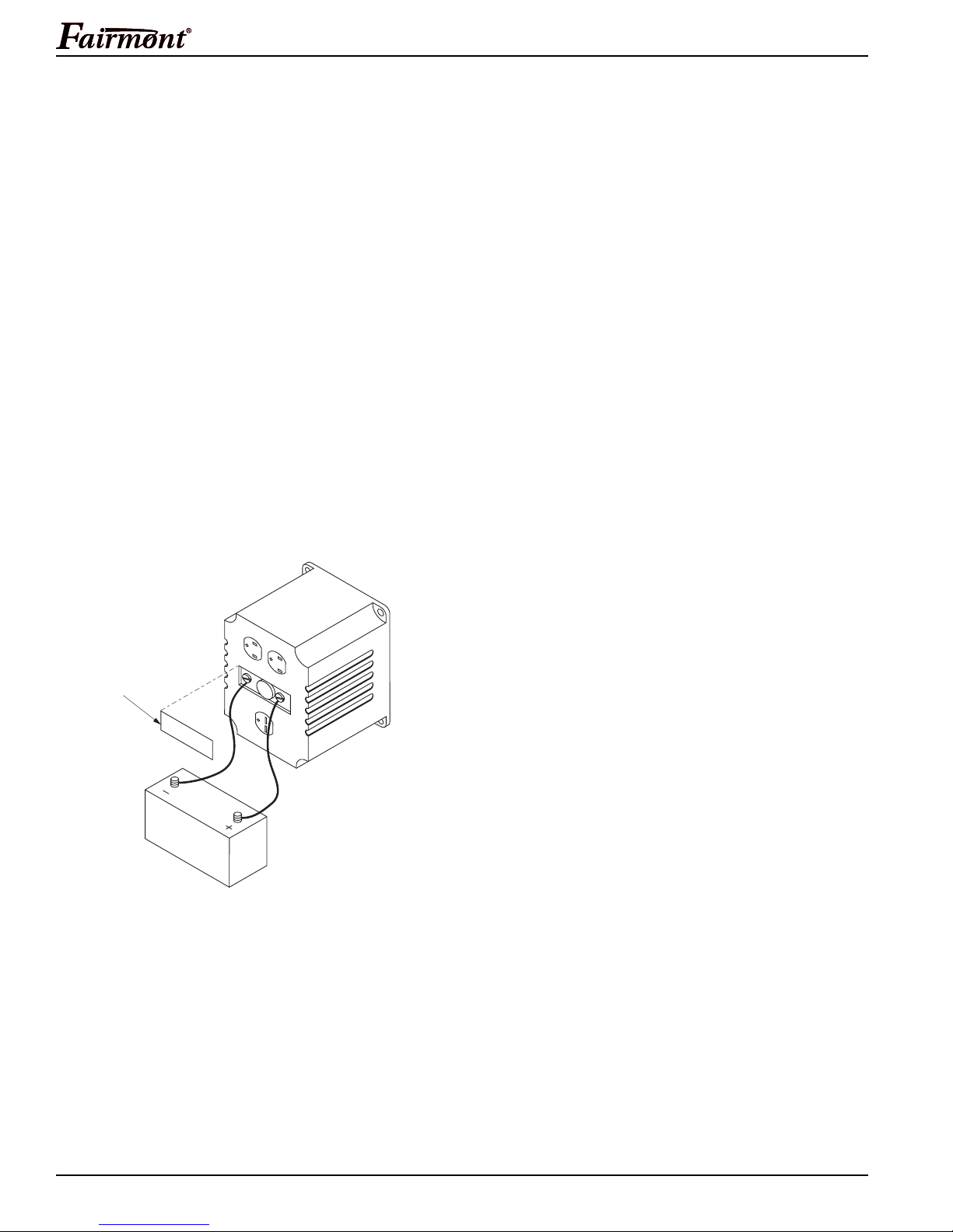
Flashing The Field
If voltage will not build up in the unit, it may be
necessary to flash the field by connecting a 6 volt battery
to the brush leads.
1. Remove cover plate (A).
2. Install a plug-in voltmeter into one of the receptacles.
3.
Connect two leads to the positive (+) and negative (–)
terminals of a 6 volt dry cell battery.
4. Make sure there is no load connected to the
alternator. Start hydraulic flow to the unit.
5. Momentarily touch the positive brush holder (right
side) with the positive (+) lead from the 6 volt battery,
while the negative (–) lead is attached to the negative brush holder (left side). Observe the voltmeter.
Remove the positive (+) lead as soon as voltage
starts to build up.
Note: No other alternator components require
maintenance.
H6635 / 42276 Portable Alternator
Flashing The Field
A
Greenlee / A Textron Company 12 4455 Boeing Dr. • Rockford, IL 61109-2988 USA • 815-397-7070
Page 13

Troubleshooting
H6635 / 42276 Portable Alternator
Before troubleshooting, determine whether the problem
is in the tool, the hoses, or the power source. Substitute
a tool, hoses, or power source known to be in good
working order to eliminate the item that is not operating.
Problem Probable Cause Probable Remedy
Tool doesn’t operate. Improper power source. Verify that the power source meets the
Hydraulic fluid level low. Check the fluid level. Check system
Incorrect hydraulic fluid viscosity. Use hydraulic fluid with the correct
Tool operates slowly or Hydraulic fluid cold. Allow fluid to warm to the
erratically. operating temperature. Actuate
Power source not adjusted correctly. Refer to the power source operator’s
If the problem is in the tool, see the troubleshooting table
in this manual. If the problem is in the power source, see
the troubleshooting section of the power source instruction manual.
specifications. See the Specifications
and Parts manual.
for leaks.
viscosity. See the Specifications
and Parts manual.
the tool intermittently to reduce the
warming time.
manual. Set the flow and pressure
to correspond with the tool.
Hydraulic fluid level low. Check the fluid level. Check system
for leaks.
Air in the hydraulic system. See power source manufacturer’s
instructions for removing air from
the system.
Incorrect hydraulic fluid viscosity. Use hydraulic fluid with the correct
viscosity. See the Specifications
and Parts manual.
Tool feels hot. Hydraulic fluid level low. Check the fluid level. Check for leaks.
Incorrect hydraulic fluid viscosity. Use hydraulic fluid with the correct
viscosity. See the Specifications
and Parts manual.
Hydraulic fluid dirty. See the power source owner’s manual
for procedure to replace hydraulic oil
and filter.
Greenlee / A Textron Company 13 4455 Boeing Dr. • Rockford, IL 61109-2988 USA • 815-397-7070
Page 14
Disassembly
H6635 / 42276 Portable Alternator
Complete disassembly of the tool is not recommended.
If a complete overhaul is necessary, return the tool to
your nearest Fairmont authorized service center.
The disassembly procedure is divided into sections of
the tool. Disassemble only the section(s) necessary to
complete the repair.
Disassemble the tool on a flat, clean surface. Take care
not to lose or damage any parts that may fall free during
disassembly.
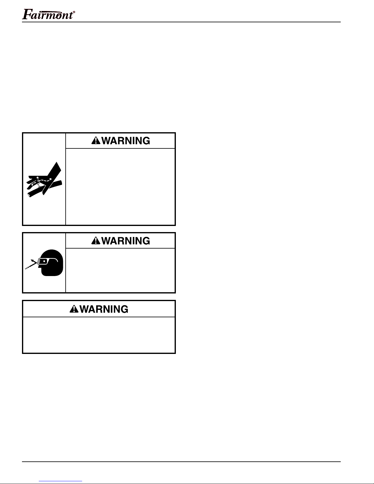
Skin injection hazard:
High pressure oil easily punctures
skin causing serious injury, gangrene
or death. If injured seek medical help
immediately to remove oil.
Do not use fingers or hands to
check for leaks.
Depressurize hydraulic system
before servicing.
Alternator assembly
1. Remove cap screws (24), wrought washers (25) and
elastic stop nuts (26). Remove ground lug (23) and
end bell (22). Remove cap screw (21).
2. Remove cap screw (20), lock washer (19) and
wrought washer (18) from mounting plate (1).
Remove spacer (17).
3. Remove stator (15) and rotor (14).
4. Remove cap screws (3), lock washers (4) and hex
nuts (5). Remove adapter (2) from mounting plate (1).
Hydraulic Motor and Manifold
1. Remove cap screws (7), hex nuts (5) and lock
washers (8). Remove hydraulic motor (6) and
attached components from mounting plate (1).
2. Loosen set screw (13) and remove drive shaft (12).
3. Remove bolts (11). Remove manifold (10) from
hydraulic motor (6). Remove O-rings (9).
4. If necessary remove flow control cartridge (29) from
manifold (10).
Note: Do not attempt to adjust or disassemble flow
control cartridge. If necessary, replace with new,
factory preset cartridge.
Wear eye protection when operating
or servicing this tool.
Failure to wear eye protection could
result in serious eye injury from
flying debris or hydraulic oil.
Do not disconnect tool, hoses, or fittings while
the tool is running or if the hydraulic fluid is hot.
Exposure to hot hydraulic fluid could cause
serious burns.
Mounting Plate
1. Remove cap screw (7), lock washer (8), and carrying
handle (27) from top of mounting plate (1).
2. Remove rubber feet (28) from mounting plate (1).
Greenlee / A Textron Company 14 4455 Boeing Dr. • Rockford, IL 61109-2988 USA • 815-397-7070
Page 15

H6635 / 42276 Portable Alternator
Inspection
Clean all parts with solvent and dry them thoroughly.
Inspect each component as described in this section.
Replace any component that shows wear or damage.
1. Hydraulic Motor (6) and Manifold (10): Mating
surfaces, cavities, oil passageways, etc.; must
be smooth and free of grooves or nicks.
If either component has grooves or nicks,
replace component.
2. Flow Control Cartridge (29): All surfaces must
be free of grooves, nicks or cracks. DO NOT
DISASSEMBLE FLOW CONTROL CARTRIDGE.
If necessary, replace with a new, factory preset
cartridge.
3. Drive Shaft (12): All surfaces must be smooth and
free of grooves or nicks. If component is damaged,
replace.
4. Rotor (14) and Stator (15): All surfaces of rotor and
stator must be smooth and free of grooves, nicks or
cracks. If component has grooves, nicks, or cracks,
replace the component.
5. Adapter (2) and End Bell (22): All surfaces must be
free of cracks. Examine outlets in end bell. If either
component is damaged, replace component.
6. O-rings: Always replace O-rings in components that
have been disassembled with new O-rings during
assembly. A packing kit is available that includes all
O-rings and gaskets.
Assembly
Refer to the Illustration(s) and Parts List for correct
orientation and placement of parts.
Replace any O-rings, V-rings, seals, and gaskets on
parts that have been disassembled. Apply hydraulic fluid
or O-ring lubricant to all O-rings and all metal surfaces
which they must slide over. When installing an O-ring
which must slide over sharp surfaces, use a rolling
motion and be careful not to damage the O-ring.
Wherever the assembly results in metal-to-metal contact,
coat the surfaces with hydraulic fluid or O-ring lubricant.
Mounting Plate
1. Install rubber feet (28) onto mounting plate (1).
2. Secure carrying handle (27) to top of mounting plate
(1) with cap screw (7) and lock washer (8).
Hydraulic Motor and Manifold
1. If removed, install flow control cartridge (29) into
manifold (10). Torque to 40-45 ft-lb.
Note: Do not attempt to adjust flow control
cartridge. If necessary, replace with new,
factory preset cartridge.
2. Install O-rings (9). Install manifold (10) onto
hydraulic motor (6) and secure with bolts (11).
Torque to 25 ft-lb.
3. Install drive shaft (12) onto hydraulic motor (6).
Secure drive shaft with set screw (13).
4. Install hydraulic motor (6) and attached components
to mounting plate (1) with cap screws (7), hex nuts
(5) and lock washers (8).
Alternator Assembly
1. Secure adapter (2) to mounting plate (1) with cap
screws (3), lock washers (4) and hex nuts (5).
2. Install rotor (14) onto tapered end of drive shaft (12).
3. Position spacer (17) on mounting plate (1). Secure
stator (15) to mounting plate (1) with cap screws
(20), lock washer (19) and wrought washer (18).
Install cap screws (21) into rotor (14). Torque to
150 in-lb.
4. Position end bell (22) onto stator (15). Secure end
bell (22), stator (15) and adapter (2) with cap screws
(24), wrought washers (25) and elastic stop nuts
(26). Be sure to slip end bell ground wire eyelet and
ground lug (23) over the lower mounting cap screw
(24) before securing end bell (22).
Greenlee / A Textron Company 15 4455 Boeing Dr. • Rockford, IL 61109-2988 USA • 815-397-7070
Page 16
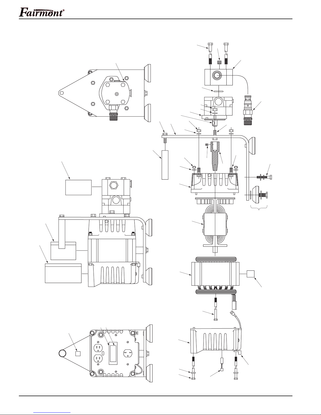
Illustration
H6635 / 42276 Portable Alternator
11
16
9
5
8
6
7, 8
27
32
37
1
5
4
26
25
2
30
10
29
7
3
13
12
18, 19, 20
28
34
33
31
36
38
14
15
17
21
Greenlee / A Textron Company 16 4455 Boeing Dr. • Rockford, IL 61109-2988 USA • 815-397-7070
23
24 25 22
35
Page 17

Parts List
H6635 / 42276 Portable Alternator
Key 78-3310- Part No. Description Qty
UPC No.
1 43771 153977 Plate, mounting ................................................................................. 1
2 43772 153952 Adapter.............................................................................................. 1
3 41242 F001007 Cap screw, 3/8 x 1" hex head ........................................................... 4
4 41358 F011455 Lock washer, 3/8" Hi-collar ............................................................... 4
5 41290 F007020 Hex nut, 3/8" ..................................................................................... 6
6 43773 153948 Motor, hydraulic................................................................................. 1
7 41255 F001125 Cap screw, 3/8 x 1-1/4" hex head ..................................................... 3
8 41244 F001025 Lock washer, 3/8" .............................................................................. 7
9* 43775 F013941 O-ring, 1-3/16 x 1/16" - 70 ................................................................. 2
10 43776 153978 Manifold, hydraulic ............................................................................ 1
11 700522475 Bolt, 3/8 x 4.66" hex head ................................................................. 4
12 43778 153980 Drive shaft ......................................................................................... 1
13 43779 F013049 Set screw, 1/4 x 5/16" cup pt hex socket head ................................. 1
14 43457 F024306 Rotor ................................................................................................. 1
15 43456 49893 Stator................................................................................................. 1
16 43231 F010568 Pipe plug, 1/2 M NPT hex socket head ............................................. 1
17 43780 153981 Spacer, .34 I.D. x 1.25" ..................................................................... 1
18 41257 F001362 Wrought washer, 5/16" ...................................................................... 1
19 F001100 Lock washer, 5/16" ............................................................................ 1
20 41310 F009663 Cap screw, 5/16 x 2" hex head ......................................................... 1
21 43781 F024308 Cap screw, 5/16 x 5-3/4" hex head ................................................... 1
22 43458 F024307 End bell ............................................................................................. 1
23 43782 F024309 Ground lug ........................................................................................ 1
24 43783 F006822 Cap screw, 1/4 x 5" hex head ........................................................... 4
25 41245 F001050 Wrought washer #10 (.190)............................................................... 8
26 41431 F013588 Hex stop nut, 1/4" elastic .................................................................. 4
27 43784 153982 Handle, carrying ................................................................................ 1
28 43785 F024298 Rubber foot ....................................................................................... 4
29 43786 F024297 Cartridge, flow control ....................................................................... 1
30 43737 F010989 Pipe plug, 1/4" M NPT ....................................................................... 1
31 41547 F015482K1 Decal, Greenlee/Fairmont ................................................................. 1
32 43788 137156 Decal, Specifications ......................................................................... 1
33 47789 137199 Decal, Warning - This Unit Should Not ............................................. 1
34 43790 157175 Decal, Danger - Electrical Shock Hazard .......................................... 1
35 FOR004494 Alternator brushes............................................................................. 2
36 55037 52025134 End bell cover ................................................................................... 1
37 F002941 Key .................................................................................................... 1
38 52021541 Decal, WEEE compliance ................................................................. 1
• 43774 155250 Packing Kit (see note)
(includes item marked with asterisk*)................................................ 1
Note: Packing Kit (155250) also includes sealing components for
Hydraulic Motor (153948) and Flow Control Cartridge (F024297).
Greenlee / A Textron Company 17 4455 Boeing Dr. • Rockford, IL 61109-2988 USA • 815-397-7070
Page 18
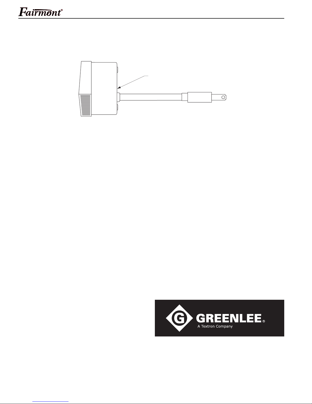
Accessories (Optional)
UPC No.
Key 78-3310- Part No. Description Qty
1 F024537 Meter (Prime Instruments #123) ....................................................... 1
H6635 / 42276 Portable Alternator
1
Greenlee / A Textron Company 18 4455 Boeing Dr. • Rockford, IL 61109-2988 USA • 815-397-7070
USA 800-435-0786 Fax: 800-451-2632
815-397-7070 Fax: 815-397-1865
Canada 800-435-0786 Fax: 800-524-2853
International +1-815-397-7070 Fax: +1-815-397-9247
4455 Boeing Drive • Rockford, IL 61109-2988 • USA • 815-397-7070
An ISO 9001 Company
www.greenlee.com
•
Greenlee Textron Inc. is a subsidiary of Textron Inc.
Printed in USA
 Loading...