

Fairford agility Series, agility AGY-103, agility AGY-101, agility AGY-105, agility AGY-107 User Manual
...Page 1

Innovation in soft starter technology
TM
agility
USER MANUAL
MAN-AGY-001. Version 04
Page 2

1
agilityTM Series Soft Start User Manual
MAN-AGY-001. Version 04. 21/09/2018
Page 3

2
agilityTM Series Soft Start User Manual
MAN-AGY-001. Version 04. 21/09/2018
TM
agility
user manual
Fairford Electronics Ltd
Bristow House
Gillard Way, Ivybridge
PL21 9GG
UK
www.fairford.com
© 2018 by Fairford Electronics, all rights reserved
Copyright subsists in all Fairford Electronics deliverables including magnetic, optical and/or any
other soft copy of these deliverables. This document may not be reproduced, in full or in part,
without written permission. Enquiries about copyright of Fairford Electronics deliverables should
be made to Fairford Electronics Ltd. If, by permission of the copyright owner, any part of this
document is quoted, then a statement specifying the original document shall be added to the
quotation. Any such quotation shall be according to the original (text, figure or table) and may
not be shortened or modified.
Page 4

3
agilityTM Series Soft Start User Manual
MAN-AGY-001. Version 04. 21/09/2018
Contents
Safety .................................................................................................................................. 7
Mechanical Installation .................................................................................................... 8
Mounting ...................................................................................................................................... 8
Requirements for an Enclosure ................................................................................................. 8
Enclosure Ventilation .................................................................................................................. 8
Altitude Derate ............................................................................................................................ 8
Dimensions .................................................................................................................................. 9
Horizontal Mounting ................................................................................................................. 10
Mechanical Specification .......................................................................................................... 10
Electrical Installation ...................................................................................................... 11
Warnings .................................................................................................................................... 11
Electrical Supplies ..................................................................................................................... 11
General Specification ................................................................................................................ 12
Short Circuit Protection ............................................................................................................ 15
Electromagnetic Compatibility ................................................................................................ 16
Wire Sizes and Torques ............................................................................................................. 16
Motor Overload Protection ...................................................................................................... 17
Electrical Connections .............................................................................................................. 18
Main Circuit Wiring Diagram ................................................................................................... 18
Control Terminal Connection ................................................................................................... 19
Control Terminal Functions ..................................................................................................... 19
Digital Input 2 (D2) Selectable Functions ................................................................................ 19
Digital Output 21/22 Selectable Functions ............................................................................. 19
3-Wire Control Circuit Wiring Diagram ................................................................................... 20
2-Wire Control Wiring Diagram ................................................................................................ 20
Configuration and Parameters ...................................................................................... 21
Display and Controls ................................................................................................................. 21
Auto Setup Procedure (Auto App)............................................................................................ 22
Setup by Individual Parameter Settings (Advanced) ............................................................. 22
Auto Application Setup Parameter Settings .......................................................................... 22
Operation Local Motor Start ...................................................................................................... 23
Auto Application Setup ............................................................................................................. 23
Menu Structure ................................................................................................................ 24
Function Descriptions ..................................................................................................... 27
Page 5

4
agilityTM Series Soft Start User Manual
MAN-AGY-001. Version 04. 21/09/2018
Trip and Fault Codes ........................................................................................................ 36
Communication ............................................................................................................... 39
Modbus RTU Serial Communications ...................................................................................... 39
Modbus RTU Communications Interface ................................................................................ 39
Modbus RTU Connections ......................................................................................................... 39
Modbus Communications Configuration
Transmission Modes
Message Structure For RTU Mode
Address
..................................................................................................................................... 40
Function Code
Data Field
.................................................................................................................................. 40
................................................................................................................ 40
...................................................................................... 40
......................................................................................................................... 40
........................................................................... 40
CRC .............................................................................................................................................. 41
Supported Functions
Write Multiple Registers
............................................................................................................. 41
....................................................................................................... 42
Memory Map .............................................................................................................................. 42
Message Timing ......................................................................................................................... 42
Modbus RTU Parameters ................................................................................................ 43
Special Modbus Registers ......................................................................................................... 88
Modbus PNU Alphabetical Cross Reference ........................................................................... 94
Updating Firmware ......................................................................................................... 95
Update Procedure ..................................................................................................................... 95
Instruction for Updating ........................................................................................................... 95
Applications ...................................................................................................................... 97
Motor Suitability and Associated Considerations ................................................................. 97
Suitability ................................................................................................................................... 97
Induction Motor Characteristics.............................................................................................. 97
Rating.......................................................................................................................................... 97
Maximum Motor Cable Length ................................................................................................ 98
Power Factor Correction Capacitors ....................................................................................... 98
Lightly Loaded, Small Motors ................................................................................................... 98
Motors Fitted with Integral Brakes ......................................................................................... 98
Older Motors .............................................................................................................................. 98
Wound-rotor or Slip-ring Motors ............................................................................................. 98
Enclosures .................................................................................................................................. 98
EU Compliance with the EMC Directive ................................................................................... 99
Page 6

5
agilityTM Series Soft Start User Manual
MAN-AGY-001. Version 04. 21/09/2018
Fuses ........................................................................................................................................... 99
Rules for Specific Applications ................................................................................................. 99
High Inertia Loads ..................................................................................................................... 99
Frequent Starting ...................................................................................................................... 99
Soft-Stopping ............................................................................................................................. 99
Reversing Configuration ........................................................................................................... 99
Replacement of Fluid Couplings ............................................................................................ 100
Two-speed Motor Applications .............................................................................................. 100
Overhauling Loads .................................................................................................................. 100
Application Table ..................................................................................................................... 100
Concepts and principles of fixed-speed induction motor starting and control. .............. 102
Introduction ............................................................................................................................. 102
The Induction Motor ............................................................................................................... 102
Starting Induction Motors ...................................................................................................... 105
Electro-Mechanical Methods Of Starting .............................................................................. 105
The Semiconductor Motor Controller ................................................................................... 107
Running Induction Motors ..................................................................................................... 108
Reliability Considerations ...................................................................................................... 109
EMC .................................................................................................................................. 111
Electromagnetic Compatibility (EMC) ................................................................................... 111
Introduction ............................................................................................................................. 111
Applicable Standard Within the EU
Mandatory Requirements Within the EU ............................................................................. 111
Guidance for Installation Personnel and System Designers .............................................. 111
EMC Basic Criteria ................................................................................................................... 112
Purchasing Implications of Meeting an EMC Standard
Basic EMC Considerations ...................................................................................................... 112
Immunity .................................................................................................................................. 112
.................................................................................... 111
................................................. 112
Emissions
................................................................................................................................. 112
Emissions - Harmonics
Emissions - Radio Frequency (RF)
Emissions - Conducted
Important Systems Information
Strategies for Attaining and Maintaining EMC Compliance
Accessories ..................................................................................................................... 115
.......................................................................................................... 112
........................................................................................ 113
.......................................................................................................... 113
........................................................................................ 113
......................................... 114
Page 7

6
agilityTM Series Soft Start User Manual
MAN-AGY-001. Version 04. 21/09/2018
Power Supply (AGY-020) .......................................................................................................... 115
Connections ............................................................................................................................. 116
Control Terminal ..................................................................................................................... 116
Functions .................................................................................................................................. 116
3-Wire Control Using AGY-020 ................................................................................................ 117
2-Wire Control Using AGY-020 ................................................................................................ 117
Fan (AGY-030) ........................................................................................................................... 118
Remote Keypad (AGY-010) ...................................................................................................... 119
Network Connection ............................................................................................................... 119
Keypad Connection and Operation
....................................................................... 120
Operation ................................................................................................................................. 120
Initial Power-Up ....................................................................................................................... 120
Selecting Units To Monitor/Configure ................................................................................... 121
Keypad Installation ....................................................................................................... 123
Mounting .................................................................................................................................. 123
Sizing Guide .................................................................................................................... 124
Key to Part Numbers ............................................................................................................... 125
Notes ............................................................................................................................... 125
Page 8
7
agilityTM Series Soft Start User Manual
MAN-AGY-001. Version 04. 21/09/2018
• agilityTM soft starters contain dangerous
voltages when connected to the mains
supply. Only qualified personnel that have
been completely trained and authorised,
should carry out installation, operation and
maintenance of this equipment.
• Installation of the soft starter must be made
in accordance with existing local and national
electrical codes and regulations and have a
minimum protection rating.
• It is the responsibility of the installer to
provide suitable grounding and branch circuit
protection in accordance with local electrical
safety codes.
• This soft starter contains no serviceable or
re-usable parts.
Safety
Important information
Installers should read and understand the instructions in this guide prior to installing, operating
and maintaining the soft starter. The following symbols may appear in this guide or on the soft
starter to warn of potential hazards or to draw attention to certain information.
Dangerous Voltage
Indicates the presence of a hazardous voltage which could result in personal injury or death.
Warning/Caution
Indicates a potential hazard. Any instructions that follow this symbol should be obeyed to avoid
possible damage to the equipment, and personal injury or death.
Protective Earth (Ground)
Indicates a terminal which is intended for connection to an external conductor for protection
against electric shock in case of a fault.
Caution Statements
The examples and diagrams in this manual are included solely for illustrative purposes. The
information contained in this manual is subject to change at any time and without prior notice.
In no event will responsibility or liability be accepted for direct, indirect or consequential
damages resulting from the use or application of this equipment.
Page 9

8
agilityTM Series Soft Start User Manual
MAN-AGY-001. Version 04. 21/09/2018
Mechanical Installation
Mounting
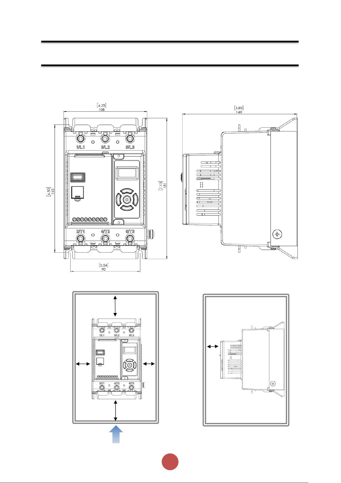
Fix the unit to a flat, vertical surface using the mounting holes (or slots) on its base-plate. The
mechanical outline diagrams, shown on Page 8, give the dimensions and mounting hole
positions for each model. Ensure that:
• The orientation of the unit has the ‘TOP’ uppermost (unless horizontally mounted –
see page 9).
• The location allows adequate front access.
• The screen can be viewed.
Do not install other equipment that generates significant heat close to the soft starter.
Requirements for an Enclosure
For a typical industrial environment, an enclosure would provide the following:
• A single location for the unit and its protection/isolation switch-gear.
• The safe termination of cabling and/or bus-bars.
• Means to effect proper air flow through the enclosure.
Enclosure Ventilation
When fitting agilityTM into a cabinet, ventilation must be provided. The heat dissipated can be
approximated with the formula: -
Starting
Watts (agilityTM) = start current(A) x start time(s) x number of starts per hour/ 1800
Running
Watts(agilityTM) = 0.4 x running amps
Use the following formula to determine the fan requirement. An allowance has been incorporated into
the formula so that the figure for Q is the air delivery in the fan supplier’s data.
Q = (4 x Wt / (T
max-Tamb
))
Q = volume of air (cubic metres per hour-m3/h)
Wt = Heat produced by the unit and all other heat sources within the enclosure (Watts) T
Maximum permissible temperature within the enclosure (40°C for a fully rated agility™)
T
= Temperature of the air entering the enclosure (°C) [to work in CFM, substitute °F for °C. Q is now
amb
in CFM]
max
=
Altitude Derate
Altitude above sea level 1000m (3281ft). Above 1000m de rate by 1% of agility™ Ie per 100m
(328ft) to a maximum altitude of 2000m (6562ft)
Ambient Temperature Derate
-20°C (-4°F) to 40°C (104°F). Above 40°C de-rate linearly by 2% of agility™ Ie per °C to a maximum
of 60°C (140°F).
Page 10
9
agilityTM Series Soft Start User Manual
MAN-AGY-001. Version 04. 21/09/2018
Air Flow
Mechanical Installation (continued)
25mm [0.98]
25mm [0.98]
75mm [2.95]
75mm [2.95]
25mm [0.98]
Dimensions
AGY-101 to AGY-113
[ ] = inch
Weight 1.97kg (3.75lb)
Fitting
Page 11
10
agilityTM Series Soft Start User Manual
MAN-AGY-001. Version 04. 21/09/2018
Mechanical Specifications
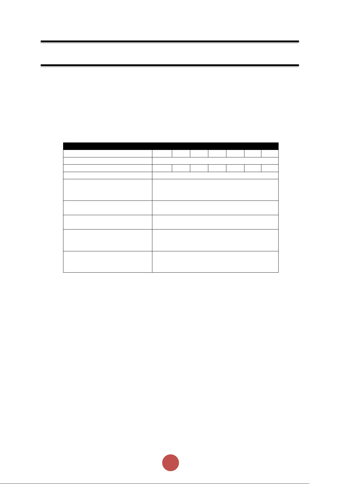
Model (AGY-)
101
103
105
107
109
111
113
Frame Size
1
Heat output (W)
9
12
14
16
20
25
30
Weight kg [lb]
1.97 [4.20]
Ambient Operating Temp.
-20°C [-4°F] to 40°C [104°F] ; above 40°C
derate linearly by 2% of agilityTM Ie per °C to
a maximum of 60°C (140°F)
Transportation and Storage
Temperature
-20°C to 60°C [-4°F to 140°F] continuous
Humidity
max 85% non-condensing, not exceeding
50% @ 40°C [104°F]
Maximum Altitude
1,000m [3281ft] ; above 1000m derate by 1%
of agilityTM Ie per 100m (328ft) to a maximum
altitude of 2,000m (6562ft)
Environmental Rating
Main Circuit: IP00 (IP20 with optional finger
guards); Control Circuit: IP20; No corrosive
gases permitted
Mechanical Installation (continued)
Horizontal Mounting
The agility
unit power in this instance – see Horizontal Rating Table (Page 13)
TM
unit may be mounted horizontally if required. It will be necessary to apply a deration to the
Mechanical Specification
Page 12

11
agilityTM Series Soft Start User Manual
MAN-AGY-001. Version 04. 21/09/2018
Electrical Installation
Warnings
Isolation
Electrical Control Supply Requirements
Fuse Protection
motor protection, between the unit and the Mains Supply, not between the unit and the motor.
Semiconductor fuses can be supplied as an option for short-circuit protection of the
semiconductors. These fuses must be fitted externally to the agilityTM chassis to comply with
certain standards. It is the responsibility of the installer and system designer/specifier to ensure
that the required standards or regulations are not affected by so doing.
Safety
of the ‘Warnings’ section at the beginning of this user manual, as well as other warnings and notes
throughout the manual.
Caution: agilityTM uses semiconductor devices in the main circuit and is not designed to
provide isolation. For this reason isolation means must be installed in the supply circuit in
accordance with the appropriate wiring and safety regulations
All electrical connections are made to power input and output terminals, control terminals
and an earth stud.
The Mains Supply and the Control Supply each require protection. Although all units have
electronic overload protection for the Soft Starter, the installer should always fit fuses, for
agilityTM soft starters contain hazardous voltages when connected to the electrical power
supply. Only qualified personnel who are trained and authorized should carry out
installation, operation and maintenance of this equipment. Refer to and carefully follow all
Electrical Supplies
The unit requires a 3-phase balanced Mains Supply to provide the power for the controlled motor,
and a 24Vdc for the internal control circuitry. The unit will not operate unless the control supply
voltage is within the specified limits.
Page 13
12
agilityTM Series Soft Start User Manual
MAN-AGY-001. Version 04. 21/09/2018
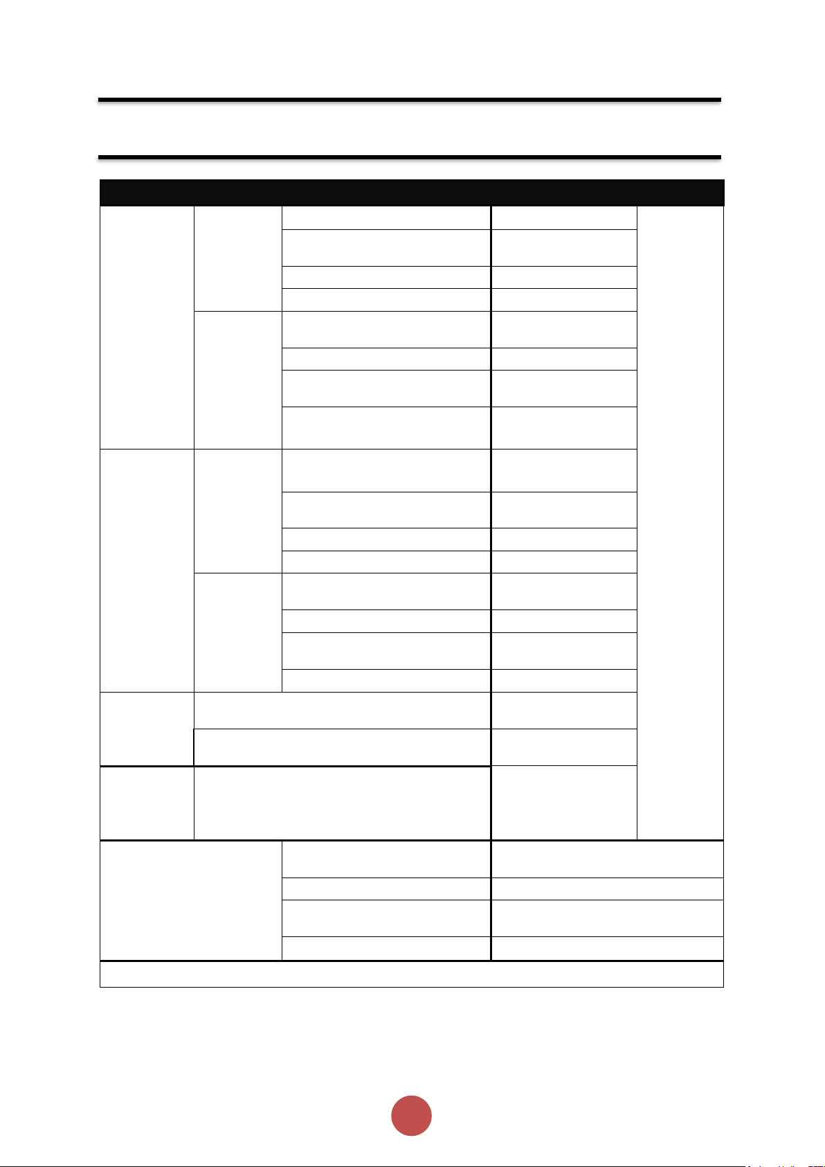
General Specification
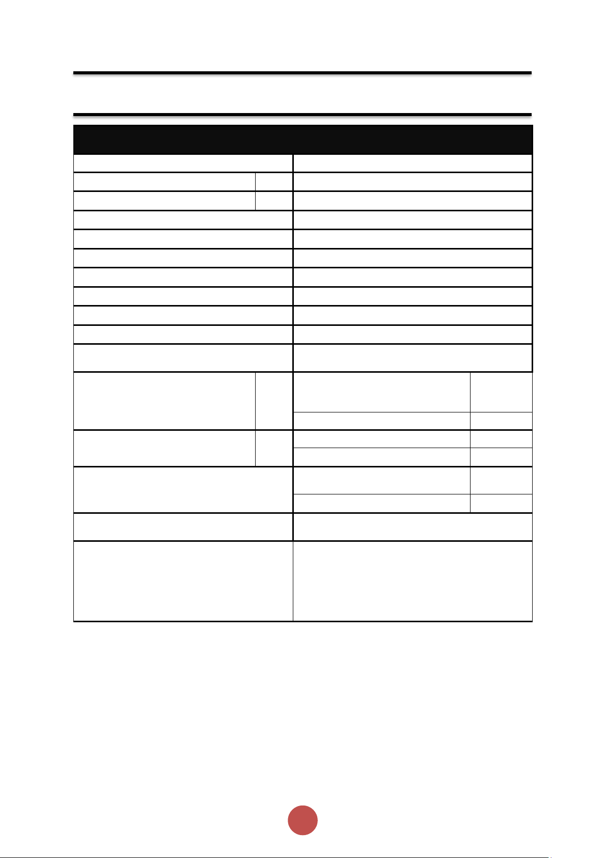
Product Standard
EN 60947-4-2: 2012
Rated operational voltages
Ue
200Vac to 600Vac (See Key to part numbers)
Rated operational current
Ie
See Rating Table
Rating index
See Rating Table
Rated frequency/frequencies
50 - 60Hz ± 5Hz
Rated duty
Uninterrupted.
Form designation
Form 1, Internally Bypassed
Method of operation
Symmetrically controlled starter
Method of control
Semi-automatic
Method of connecting
Thyristors connected between windings and supply
Number of poles
3 main poles, 2 main poles controlled by
semiconductor switching element
Rated insulation voltage
Ui
Main circuit
See Key to
part
numbers
Control supply circuit
24Vdc
Rated impulse withstand voltage
U
imp
Main circuit
6 kV
Control supply circuit
4 kV
IP code
Main circuit
IP00 (IP20
optional)
Supply and Control circuit
IP20
Overvoltage Category / Pollution
degree
III / 3
Rated conditional short-circuit current and
type of co-ordination with associated short
circuit protective device (SCPD)
Type 1 co-ordination
See Short Circuit Protection Tables for
rated conditional short-circuit current
and required current rating and
characteristics of the associated SCPD
Electrical Installation (continued)
Page 14
13
agilityTM Series Soft Start User Manual
MAN-AGY-001. Version 04. 21/09/2018
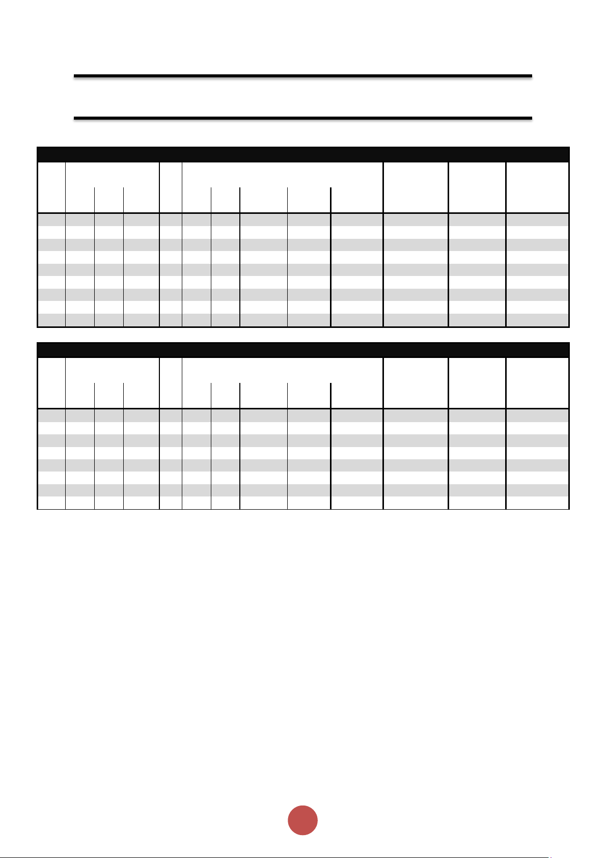
General Specification (continued)
As
Control
Supply input
0, 24V
Standard
supply
Kind of current, rated
frequency
d.c. Rated voltage Us
24Vd.c.
Maximum power consumption
12VA
Control
Programmable opto-isolated
inputs
D1, D2
circuit
Common input, marking
COM
Kind of current, rated
frequency
d.c. Rated voltage Uc
24Vd.c.
Protect with
4A
With
Control
Supply input
L, N
UL listed
fuse
extra
Supply
Kind of current, rated
frequency
a.c., 50 - 60Hz ± 5Hz
module
Rated voltage Us
110V to 230V a.c.
Rated input current
1A
Control
Programmable opto-isolated
inputs
D1, D2
circuit
Common input
COM
Kind of current, rated
frequency
a.c., 50 - 60Hz ± 5Hz
Rated voltage Uc
110V to 230V a.c.
Auxiliary
Form A – Single gap make -contact (normally
open)
13, 14
circuit 1)
Form B – Single gap break-contact (normally
closed)
21, 22
Utilization category, voltage rating, current
rating
Resistive load,
250Vac, 2A.
Cosø =0.5, 250Vac,
2A.
Electronic
Trip Class
10 (factory default), 20 or 30
(selectable)
overload relay
Current setting
7A to Ie
with manual reset and
thermal
Rated frequency
50 to 60Hz ± 5Hz
memory
Time-current characteristics
See ‘Motor Overload ‘cold’ trip curves’
1)
Compliant with Annex S of IEC 60947-1:2007 at 24Vd.c.
Electrical Installation (continued)
Page 15
14
agilityTM Series Soft Start User Manual
MAN-AGY-001. Version 04. 21/09/2018
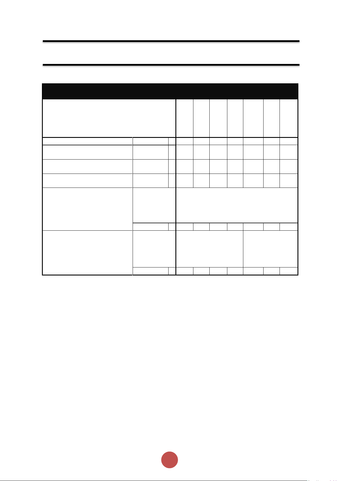
Rating Table – Vertical Mounting
Ie
kW 1)
FLA
Hp 2)
Trip Class 10
Trip Class
20
Trip Class 30
A 3)
230V
400V
500V 4)
A 3)
200V
208V
220-240V
440-480V
550-600V 4)
Ie: AC-53a:
3.5-17: 90-5
5)
Ie: AC-53a:
4-19: 90-5 5)
Ie: AC-53a:
4-29: 90-5 5)
17 4 7.5
7.5
17 3 5 5 10
15 - -
AGY-101
17 4 7.5
7.5
17 3 5 5 10
15
-
AGY-101
AGY-103
17 4 7.5
7.5
17 3 5 5 10
15
AGY-101
AGY-103
AGY-105
22
5.5
11
11
22 5 5
7.5
15
20
AGY-103
AGY-105
AGY-107
29
7.5
15
15
27
7.5
7.5
7.5
20
25
AGY-105
AGY-107
AGY-109
35
7.5
18.5
22
34
10
10
10
25
30
AGY-107
AGY-109
AGY-111
41
11
22
22
41
10
10
10
30
40
AGY-109
AGY-111
AGY-113
55
15
30
37
52
15
15
15
40
50
AGY-111
AGY-113
-
66
18.5
37
45
65
20
20
20
50
60
AGY-113
-
-
Rating Table – Horizontal Mounting
Ie
kW 1)
FLA
Hp 2)
Trip Class 10
Trip Class
20
Trip Class 30
A 3)
230V
400V
500V 4)
A 3)
200V
208V
220-240V
440-480V
550-600V 4)
Ie: AC-53a:
3.5-17: 90-5
5)
Ie: AC-53a:
4-19: 90-5 5)
Ie: AC-53a:
4-29: 90-5 5)
17 4 7.5
7.5
17 3 5 5 10
15
-
AGY-101
AGY-103
17 4 7.5
7.5
17 3 5 5 10
15
AGY-101
AGY-103
AGY-105
17 4 7.5
7.5
17 3 5 5 10
15
AGY-103
AGY-105
AGY-107
22
5.5
11
11
22 5 5
7.5
15
20
AGY-105
AGY-107
AGY-109
29
7.5
15
15
27
7.5
7.5
7.5
20
25
AGY-107
AGY-109
AGY-111
35
7.5
18.5
22
34
10
10
10
25
30
AGY-109
AGY-111
AGY-113
41
11
22
22
41
10
10
10
30
40
AGY-111
AGY-113
55
15
30
37
52
15
15
15
40
50
AGY-113
-
Electrical Installation (continued)
Minimum current ratings based on typical rated operation currents of motors for the
corresponding rated operational powers.
Current rating optimised for kW@400V & hp@440-480V - Ref IEC 60947-4-1:2009 Table G.1 where
applicable.
1)
Rated operational powers in kW as per IEC 60072-1 (primary series) corresponding to IEC current
rating.
2)
Rated operational powers in HP as per UL508 corresponding to FLA current rating.
3)
The I
4)
kW and HP ratings applicable for AGY-101-6 to AGY-113-6 models only.
5)
A duty cycle F-S of up to 90-40 (up to 40 starts per hour) is possible with optional fan fitted
and FLA rating applies for a maximum surrounding air temperature of 40oC. Above 40oC de-rate
e
linearly by 2% of Ie or FLA per oC to a maximum of 60oC.
Page 16
15
agilityTM Series Soft Start User Manual
MAN-AGY-001. Version 04. 21/09/2018
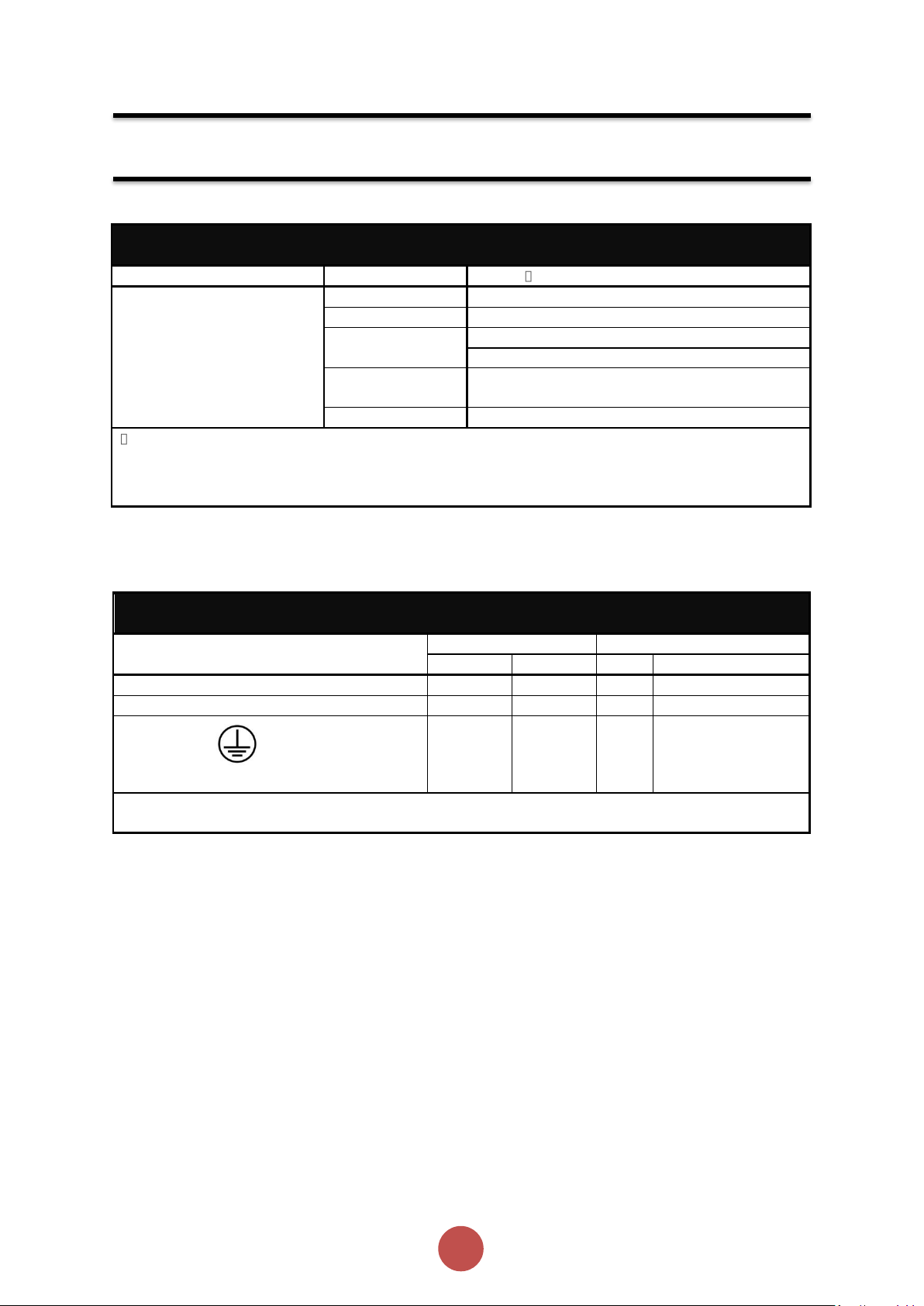
Short Circuit Protection
Type designation (AGY-)
101-6
103-6
105-6
107-6
109-6
111-6
113-6
Rated operational current
Ie A 17
22
29
35
41
55
66
Rated conditional short circuit
current
Iq
kA 5 5 5 5 5 5
10
Class J time-delay fuse #1
Maximum
rating Z1
A
30
40
50
60
70
100
125
UL Listed inverse-time delay circuit
breaker #1
Maximum
rating Z2
A
60
60
60
60
60
150
150
Semiconductor fuse (class aR)
#2
,
duty ≤ 5 starts per hour.
Type
Mersen 6,9 URD 30 _
Bussmann 170M30__
Bussmann 170M31__
Bussmann 170M32__
SIBA 20 61___
Fuse rating
A
100A
100A
160A
160A
160A
200A
200A
Semiconductor fuse(class aR),
#2
duty
> 5 starts per hour #3.
Type Mersen 6,9 URD 30 _
Mersen 6,9 URD 31 _
Bussmann 170M30__
Bussmann 170M40__
Bussmann 170M31__
Bussmann 170M41__
Bussmann 170M32__
Bussmann 170M42__
SIBA 20 61___
SIBA 20 61___
Fuse rating
A
160A
160A
200A
200A
250A
250A
250A
Electrical Installation (continued)
# 1. Suitable For Use On A Circuit Capable Of Delivering Not More Than ___I
600Volts Maximum, When Protected by Class J time delay Fuses with a Maximum Rating of ___Z1___ or
by a Circuit Breaker with a Maximum Rating of ___Z2___.
# 2. Correctly selected semiconductor fuses can provide additional protection against damage to the
agilityTM unit (This is sometimes referred to as type 2 co-ordination). These semiconductor fuses are
recommended to provide this increased protection.
# 3. Only when optional fan is fitted, see Rating table (Note 5).
___ rms Symmetrical Amperes,
q
Page 17
16
agilityTM Series Soft Start User Manual
MAN-AGY-001. Version 04. 21/09/2018
Electromagnetic Compatibility
EMC Emission levels
EN 55011
Class A
EMC Immunity levels
IEC 61000-4-2
8kV/air discharge or 4kV/contact discharge
IEC 61000-4-3
10 V/m
IEC 61000-4-4
2kV/5kHz (main and power ports)
1kV/5kHz (signal ports)
IEC 61000-4-5
2kV line-to-ground
1kV line-to-line
IEC 61000-4-6
10V
NOTICE: This product has been designed for environment A. Use of this product in environment
B may cause unwanted electromagnetic disturbances, in which case the user may be required to
take adequate mitigation measures
Wire Sizes and Torques
Terminal
Wire Size
Torque
mm2
AWG
Nm
Ib-in
Main terminals Cu STR 75oC only
2.5 - 70
12- 2/0
9
80
Control terminals
0.5–1.5
20-16
0.8
7.0
M6 screw
Protective
Earth 1) Cu
only
≥ 10
≥ 8 8 70
1)
Protective Earth wire size based on bonding conductor requirements of UL508 Table 6.4 and UL508A
Table 15.1.
Electrical Installation (continued)
Page 18

17
agilityTM Series Soft Start User Manual
MAN-AGY-001. Version 04. 21/09/2018
Electrical Installation (continued)
Motor Overload Protection
agilityTM provides full motor overload protection, configurable through the user interface.
Overload trip settings are determined by the Motor Current setting and the Trip Class setting. Trip
class choices are Class 10, Class 20, and Class 30. The agilityTM soft starters are protected using
full I2T motor overload with memory. See Appendix 1 for sizing guide.
Please note: When the overload has tripped, there is a forced cooling time to allow the
overload to recover before the next start.
The ‘warm’ trip times are 50% of the ‘cold’ trip time
Page 19
18
agilityTM Series Soft Start User Manual
MAN-AGY-001. Version 04. 21/09/2018
Electrical Installation (continued)
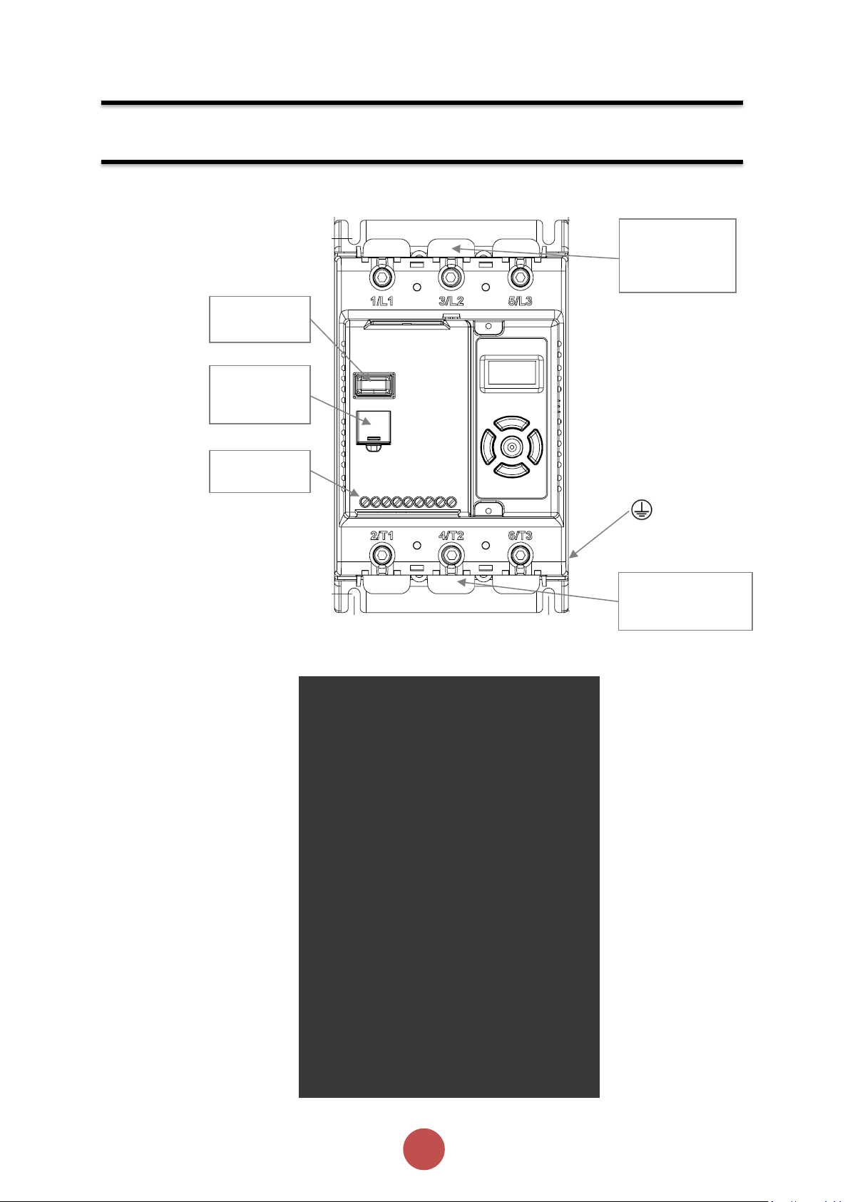
3-Phase Electrical
Supply
Connections
(L1, L2, L3)
RJ45
connector
(Modbus RTU)
USB
Connector
Control
Terminals
AC Induction Motor
Connections
(T1, T2, T3)
Electrical Connections
Main Circuit Wiring Diagram
Page 20
19
agilityTM Series Soft Start User Manual
MAN-AGY-001. Version 04. 21/09/2018
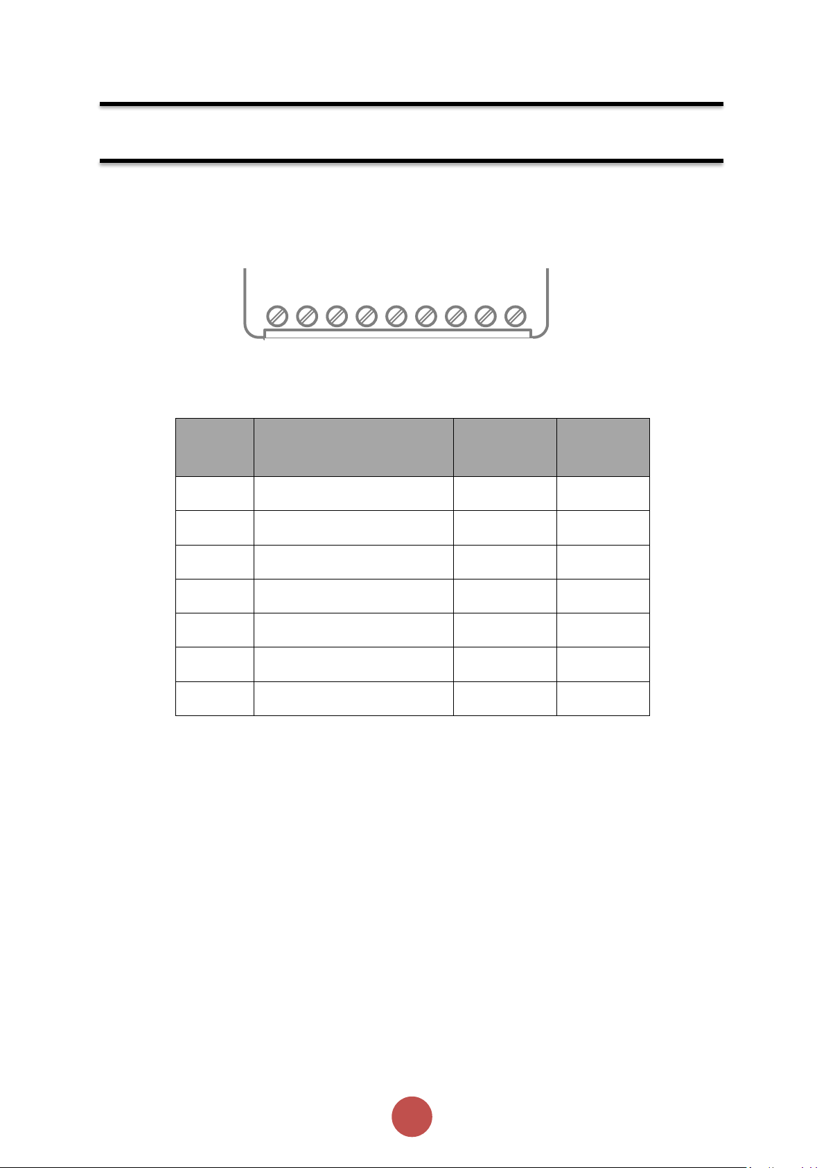
Terminal
Description
Function
Selectable
Note
24Vdc
Control Supply +Us
No
#1
0V
Control Supply -Us
No COM
Digital Inputs Common
No D1
Digital Input 1
No
#2
D2
Digital Input 2
Yes
#2
13/14
Main Contactor Control (Run
Relay)
No
#3
21/22
Fault Relay
Yes
#3
24V
COM
0V
13
D1
14
D2
22
21
Electrical Installation (continued)
Control Terminal Connection
Control Terminal Functions
#1 24V dc Specification: 24V 10VA, residual ripple < 100Mv, spikes/switching peaks < 240mv,
#2 The voltage applied to the digital inputs D1 and D2 must not exceed 24V dc
#3 230Vac, 1A, AC15. 30Vdc, 0.5A resistive
Digital Input 2 (D2) Selectable Functions
Different functions may be assigned to Digital Input 2 in the I/O menu. Available assignments are:
Reset
Hold Start Ramp
Enable
Fire Mode (In Fire Mode all trips are disabled)
Digital Output 21/22 Selectable Functions
The output may be mapped to Fault or Top-of-Ramp indication
Page 21
20
agilityTM Series Soft Start User Manual
MAN-AGY-001. Version 04. 21/09/2018
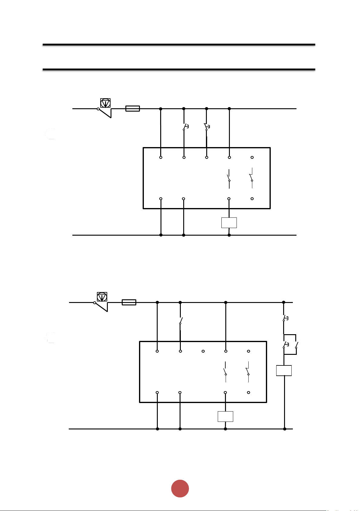
Note: 110 – 230V control supply
possible with optional control
supply module (AGY-020)
Electrical Installation (continued)
K1
0V
Start
Stop
24V
D1
D2
13
0V
COM
14
21
22
FU1
24Vdc
K2.2
K1
0V
24V
D1
D2
13
0V
COM
14
21
22
FU1
24Vdc
Note: 110 – 230V control supply
K2.1
K2
Start
Stop
3-Wire Control Circuit Wiring Diagram
2-Wire Control Wiring Diagram
possible with optional control
supply module (AGY-020)
Page 22
21
agilityTM Series Soft Start User Manual
MAN-AGY-001. Version 04. 21/09/2018
Configuration and Parameters
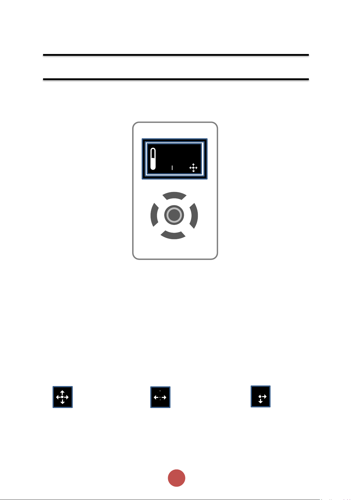
Local
Status messages
Instantaneous motor current
Control scheme: Local, Control terminal, Modbus RTU
Motor overload level; 0 to 100%
Keypad guidance wizard: Displays which keys are valid for specific menu items
Status LED (incorporated into centre button) – Green/Red
READY
32A
Local
Control keypad
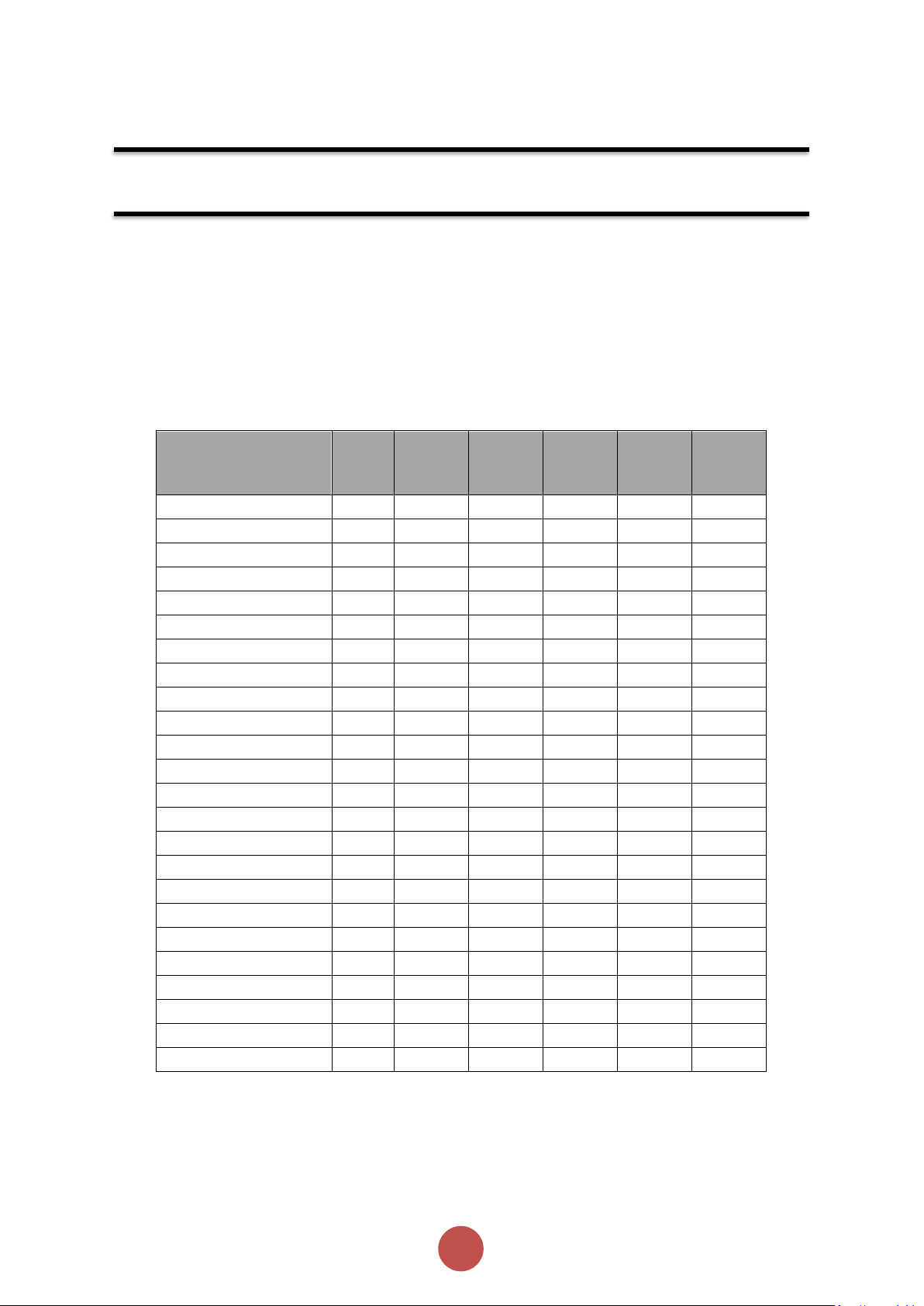
Display and Controls
Key
Keypad Guidance Examples
All keys active Left & Right keys active Right, Down & Centre keys active
Note: A flashing centre button indicates that a menu item may be selected or saved.
Page 23
22
agilityTM Series Soft Start User Manual
MAN-AGY-001. Version 04. 21/09/2018
Initial
Volts
Start
Time
Stop
Time
Trip
Class
Current
Limit
Current
Limit
Time
Unit
% s s
-
*FLC
s
Default
20%
10 0 10
3.5
30
Heavy
40%
10 0 20 4 40
Agitator
30%
10 0 10
3.5
25
Compressor 1
40%
15 0 20
3.5
25
Compressor 2
35% 7 0
10
3.5
25
Conveyor Loaded
10%
10 7 20
5.5
30
Conveyor Unloaded
10%
10 7 10
3.5
30
Crusher
40%
10 0 30
3.5
60
Fan High Inertia
40%
10 0 30
3.5
60
Fan Low Inertia
30%
15 0 10
3.5
30
Grinder
40%
10 0 20
3.5
40
Mill
40%
10 0 20
3.5
40
Mixer
10%
10 0 20 4 25
Moulding M/C
10%
10 0 10
4.5
25
Press Flywheel
40%
10 0 20
3.5
40
Pump 1
10%
10
60
10
3.5
25
Pump 2
10%
10
60
20
3.5
25
PumpJack
40%
10 0 20
3.5
40
SawBand
10%
10 0 10
3.5
25
SawCircular
40%
10 0 20
3.5
40
Screen Vibrating
40%
10 0 20
4.5
40
Shredder
40%
10 0 30
3.5
60
Wood Chipper
40%
10 0 30
3.5
60
Configuration and Parameters (continued)
Auto Setup Procedure (Auto App)
Allows the user to change all of the parameters at once to settings that are typical for general applications.
One or more parameters as can be adjusted to fine tune the settings for your specific application.
Setup by Individual Parameter Settings (Advanced)
Allows the user to change the parameter settings one at a time.
Auto Application Setup Parameter Settings
Compressor 1 = Centrifugal, Reciprocating, Rotary Screw
Compressor 2 = Rotary Vane, Scroll
Pump 1 = Submersible: Centrifugal, Rotodynamic
Pump 2 = Positive Displacement: Reciprocating, Rotary
Page 24
23
agilityTM Series Soft Start User Manual
MAN-AGY-001. Version 04. 21/09/2018
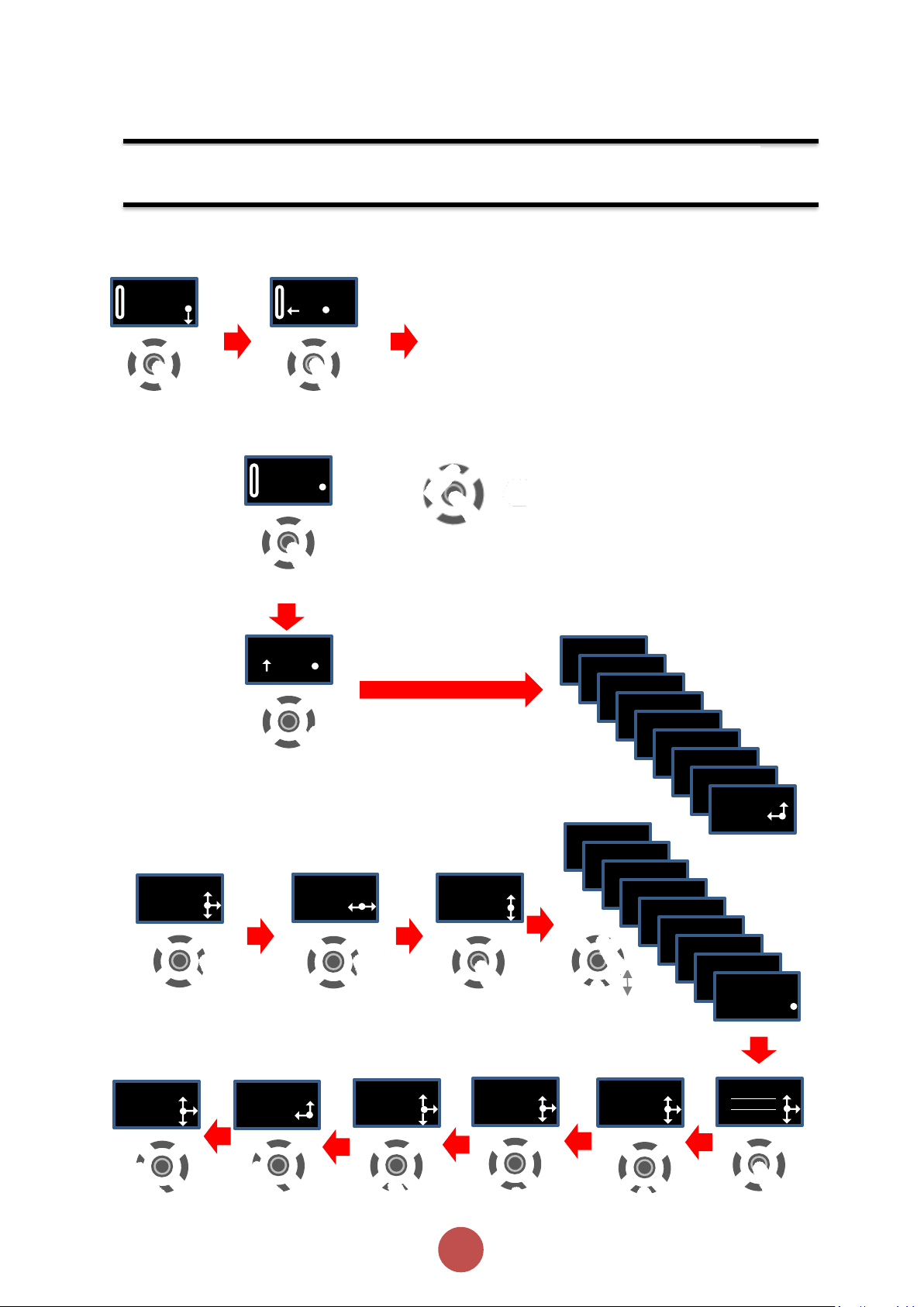
Example Navigation Method
Configuration and Parameters (continued)
Ready
Local
Monitor
I1 rms
30A
I2 rms
30A
I3 rms
30A
Overload
30A
Rotation
Delay Angle
Frequency
Serial Number
A1234567
Fire Mode
Off
Ready
Local
Local Start
No
Yes
Quick Return to Status Screen
(Centre button to adjust)
Auto Setup
Application
Default
Application
Default
30A
30A
30A
30A
Application
Application
Application
Application
Application
Application
[x24]
Application
Application
Application
Woodchipper
Application
Pump 1
Application
Pump 1
Motor Amps
22 A
Cntrl Mode
Remote
Auto Setup
Cntrl Funct
Two Wire
Operation
Local Motor Start
Auto Application Setup
Page 25
24
agilityTM Series Soft Start User Manual
MAN-AGY-001. Version 04. 21/09/2018
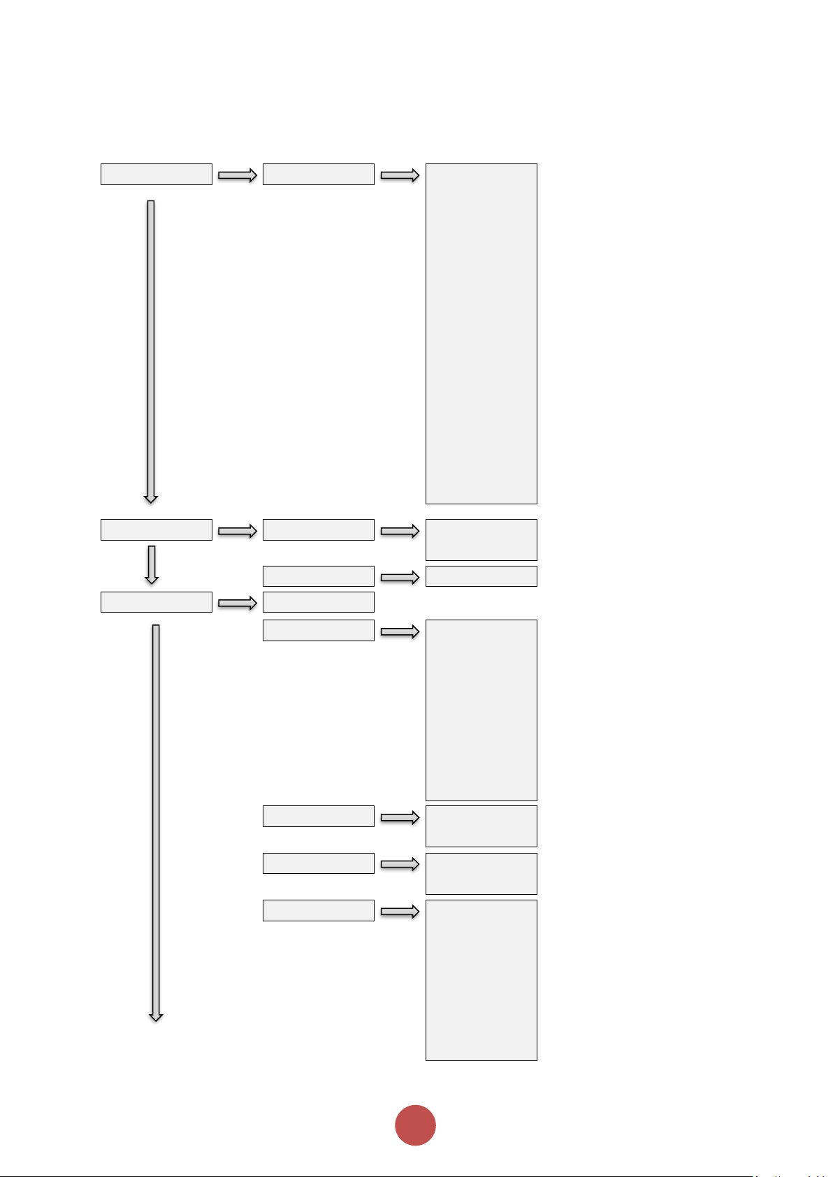
Level 0
Level 1
Level 2
Level 3
Monitor
I rms
I1 rms
I2 rms
I3 rms
Overload
Rotation
HS Temp
TempUnit
Delay Angle
Frequency
RX Bytes
TX Bytes
RX Errors
TX Errors
StartsHr
Initial Deg C
Auto Setup
Application
Default
Heavy
Agitator
Compressor 1
Compressor 2
Conveyor Loaded
Conveyor
Unloaded
Crusher
Fan High Inertia
Fan Low Inertia
Grinder
Mill
Mixer
Moulding M/C
Press Flywheel
Pump 1
Pump 2
PumpJack
Saw-Band
Saw-Circular
Screen Vibrating
Shredder
Woodchipper
Motor Amps
Cntrl Mode
Cntrl Funct
Local
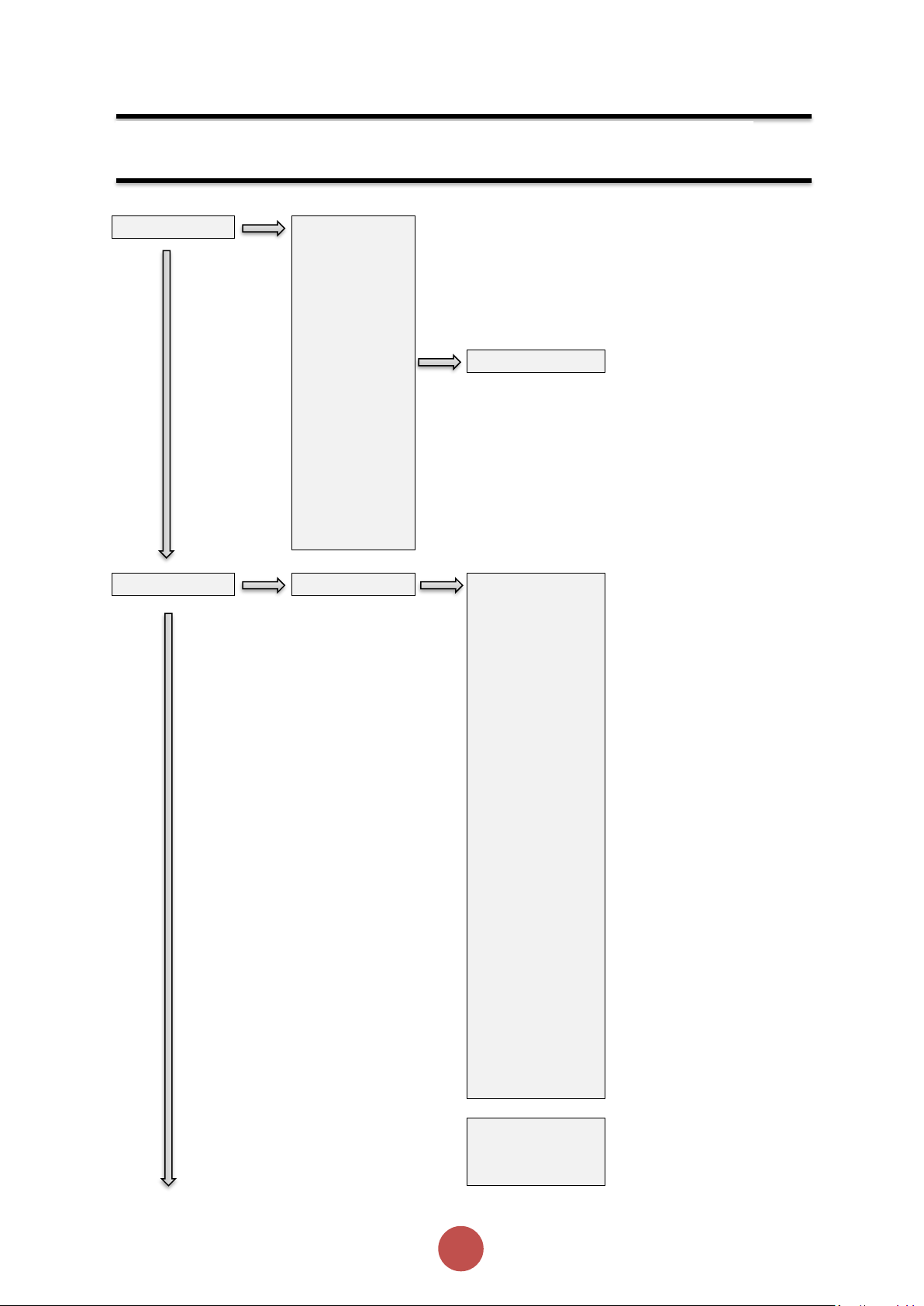
Menu Structure
Page 26
25
agilityTM Series Soft Start User Manual
MAN-AGY-001. Version 04. 21/09/2018
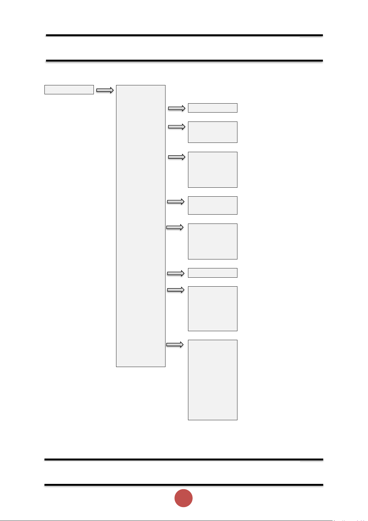
Advanced
Start Param
Start Time
Initial Volts
I Limit
I Limit Start
Limit Amps
Limit Time
Kick Start
Kick Start
Kick Time
Kick Level
Start Delay
Stop Param
Stop Time
Limit
I Limit Stop
Limit Amps
Limit Time
Protection
Motor Amps
Overload
Overload
Trip Class
Ovld Amps
Shearpin
Shearpin
Shear Amps
Shear TIme
Low Amps
I Low
I Low Amps
I Low Time
Mode
Op Mode
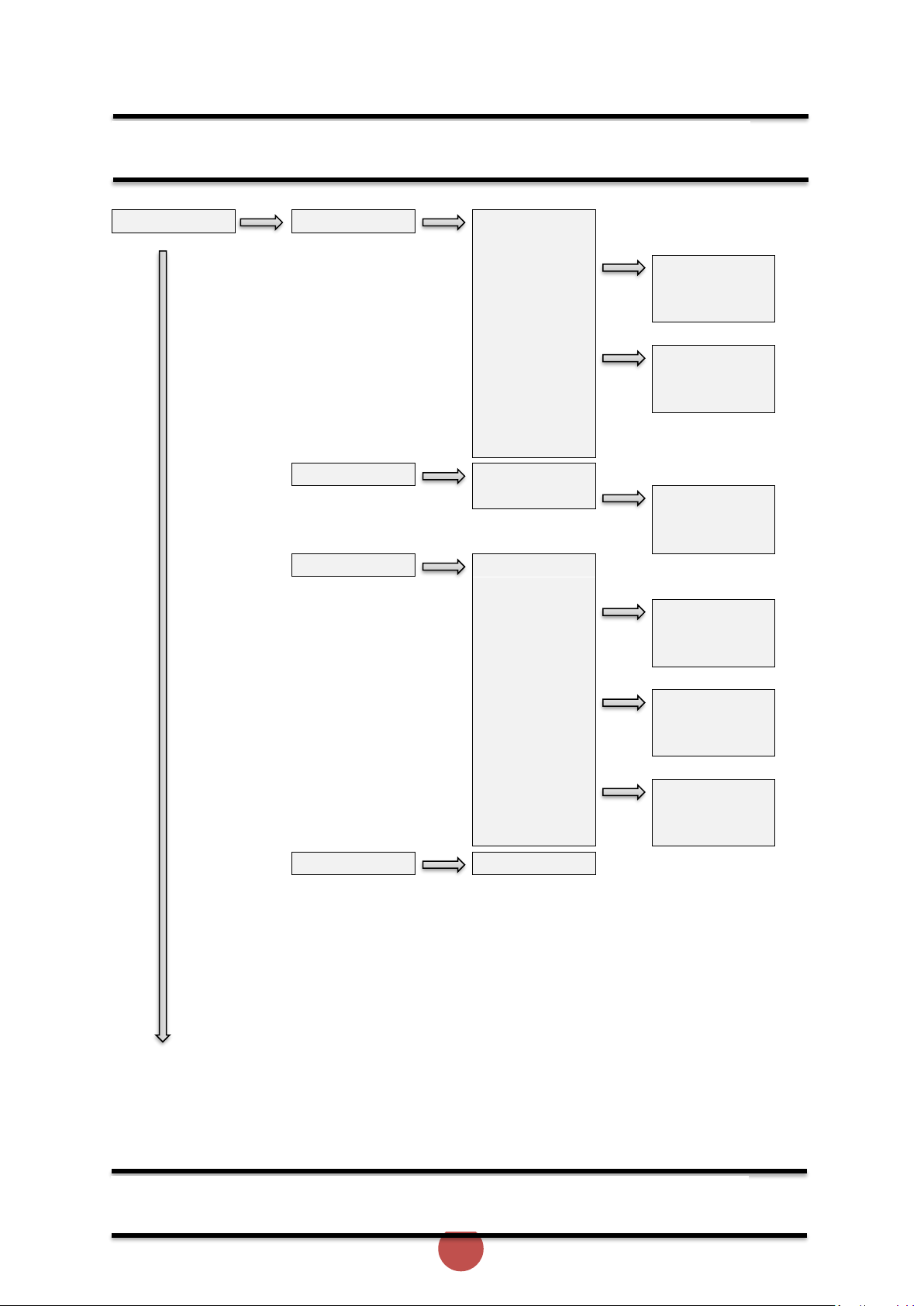
Menu Structure (continued)
Menu Structure (continued)
Page 27
26
agilityTM Series Soft Start User Manual
MAN-AGY-001. Version 04. 21/09/2018
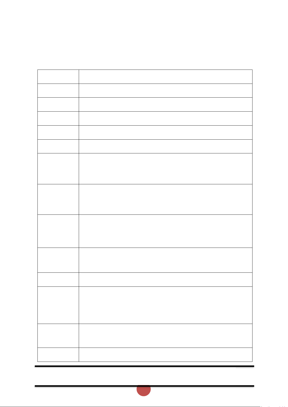
Advanced
Trips
Trip Sens
Phase Loss
Sensor Loss
Ph / SCR
Hz HighLow
I Low
I Limit Start
I Limit Stop
Overload
Shearpin
Comms
Remote
CT Fault
L1L2L3
L1L3L2
Operation 1
Operation 2
I/O Input
Cntrl Mode
Cntrl Funct
Output
RelayFunct
Log Save Log
Trip Log
Trip 0
Trip 1
Trip 2
Trip 3
Trip 4
Trip 5
Trip 6
Trip 7
Trip 8
Start Log
I Start
T Start
Stop Log
I Stop
T Stop
Totals Log
Total Events
Total Us On
Total Uc On
Total Starts
Total Runs
Total Stops
Total Trips
Total Us Off
Page 28
27
agilityTM Series Soft Start User Manual
MAN-AGY-001. Version 04. 21/09/2018
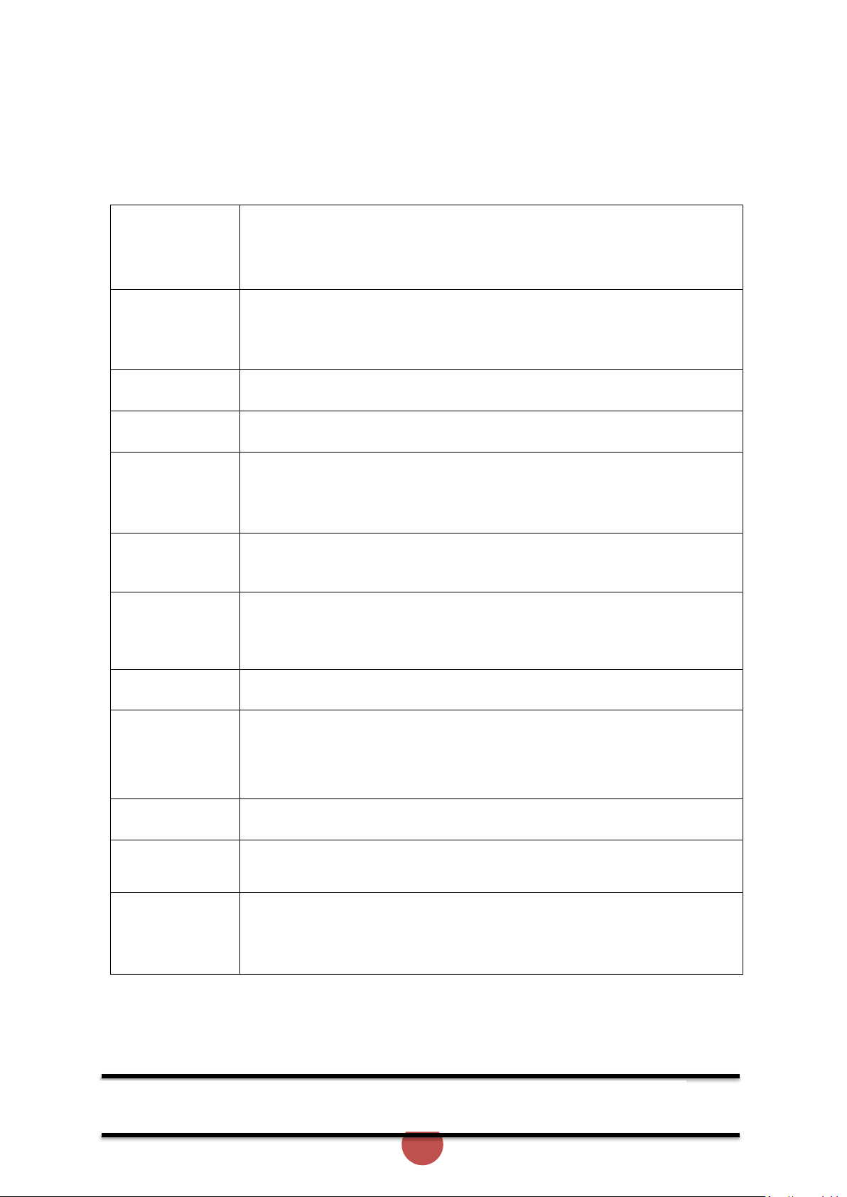
Device
Language
Factory Rst
Date
DateFormat
Time
USB
To USB
From USB
Screen
Lock Enable
Passcode
Disp Time
Scroll
Firmware
Version
Update
Network
Address
Parity
Baud
CommsTime
Keypad
Keypad Pwr
Hardware
AGY100 Ver
AGY200 Ver
AGY300 Ver
AGY400 Ver
ODB Type
About
Serial No
MenuBuild
Model No
Version
Boot Ver
Trip Class
Motor Amps
Unit Amps
Rated Amps
Function Descriptions
Menu Structure (continued)
Page 29

28
agilityTM Series Soft Start User Manual
MAN-AGY-001. Version 04. 21/09/2018
Address
Sets the Modbus address number
Application
The unit has numerous pre-set applications built in as standard.
Select the application best suited to the load.
The selected application will automatically change several parameters
and functions.
Depending on the application loaded the “Trip Class" may also change
Baud
Sets the serial communications baud rate
The available baud rates are 9600 19200 38400 57600 or 115200
Boot Ver
Software Version for the Bootloader
Cntrl Funct
Allows the Digital inputs to be mapped to different functions
Cntrl Mode must be set to "Remote"
Two Wire: D1 = Start (Reset) / Stop
Three Wire: D1 = Start (Reset) D2 = Stop
D2 Reset, D2 HoldStart , D2 Enable , D2 FireMode : Programs D2 as
shown
Cntrl Mode
Selects the method for starting and controlling the motor
Local: Control using the button on the keypad
Remote: Control using the terminals.
Modbus: Control via Modbus network
Comms
Detects if the communications bus has failed or become inactive.
To keep the bus active there must be at least one Modbus read or
write (any PNU) during the "Comms Time” period (ModbusPNU 147)
Trip On: Communication trip enabled.
Trip Off: External Trip is disabled
CommsTime
Communications trip Timeout period
To prevent a 'Communications Trip' (if enabled) the bus must be kept
active.
To keep the bus active there must be at least one Modbus read or write
(any PNU) during the
"Timeout ms” period
Cont Delay
Time allowed for external contactors to close.
Increase if contactors are driven by buffer relays or motor trips on phase
loss when start signal applied.
Decrease if response to start signal needs to be improved
Function Descriptions (continued)
Page 30

29
agilityTM Series Soft Start User Manual
MAN-AGY-001. Version 04. 21/09/2018
CT Fault
Detects if the internal current sensors have failed or reading a
very low level.
Trip On: The unit will trip if the internal current sensors fail or
the current measured falls to a very low level
Trip Off: Will continue to operate even if the sensor has failed.
Measurements and overload protection may be effected
Date
Enter current date
Date format can be set to either dd/mm/yyyy or mm/dd/yyyy. Refer to
"Date format" parameter.
DateFormat
Allows the date format to be changed
dd/mm/yy or mm/dd/yy or yy/mm/dd
Delay Angle
Internal firing delay angle in Degrees
Displayed for diagnostic purposes
Disp Time
Time for backlight on display
After the period set the back light on the screen will turn off
To reactivate touch screen anywhere. To disable set to 0
Factory Rst
Restores the unit to the factory defaults
Fan Fault
Detects if the cooling fans have failed.
Trip On: The unit trips if the cooling fans fitted to the unit fail.
Trip Off: Will continue to operate and is likely to trip on a thermal trip as
the heatsink will not be sufficiently cooled
Fire Mode
A special feature that allows the unit to operate with ALL of the trips OFF.
Set " Cntrl Funct" to "D2 FireMode" , Enabled when D2 is high
Although the unit will keep running in this mode it may become damaged.
In some instances, the damage may inhibit a subsequent starts
This is only to be used in an emergency
Frequency
The frequency of the 3-phase supply
From USB
Allows the user to load parameters stored on a USB flash drive
Uploads the parameters from the USB drive to the unit
Data is stored in CSV format.
HS Temp C
The temperature of the internal unit heatsink.
The unit will trip when the heatsink temperature exceeds 80°C.
HS Temp F
The temperature of the internal unit heatsink.
The unit will trip when the heatsink temperature exceeds 176°F
The optional cooling fans will turn on if this temperature exceeds 104°F
I Limit
Selects trip or continue if the current limit has been active for too long
Trip On: The unit will trip
Trip Off: The start will continue regardless of the motor current level
I Low
This can be used to detect if the motor is running lightly loaded.
Trip On: The unit will trip. This feature is not active during soft start and
soft stop.
Trip Off: The unit will continue to operate regardless of motor current
Function Descriptions (continued)
Page 31
30
agilityTM Series Soft Start User Manual
MAN-AGY-001. Version 04. 21/09/2018
I rms
The RMS motor current
Indicates average current of the 3 phases.
I Start
Displays the peak current during the last start.
I Stop
Displays the peak current during the last stop.
I1 rms
The RMS current on phase L1
I2 rms
The RMS current on phase L2
I3 rms
The RMS current on phase L3
Initial Volts
Percentage of the supply voltage applied to motor at the beginning of the
soft start.
Increase to provide more torque If the load fails to break away.
Decrease if the motor accelerates too quickly.
Kick Level
Percentage of the supply voltage applied to the motor during the ‘kick'
period
Increase to provide more torque If the load fails to break away.
Decrease if the motor accelerates too quickly.
Kick Start
Applies a short duration torque pulse to dislodge 'sticky' loads
On: The torque pulse is applied at start-up when complete the torque
drops to the "Initial Volts"
Off: The initial starting torque is defined by the "Initial Volts"
Kick Time
Time that the torque pulse is applied to load
Increase to provide more torque If the load fails to break away.
Decrease if the motor accelerates too quickly.
Last Trip
Limit Amps
The current in Amps at which the soft Start ramp is held.
Normally set to 350% of motor FLC.
Increase if motor fails to accelerate at required rate
The "Limit Amps" will affect actual time to start.
If set too low the motor may not accelerate to full speed.
Limit Time
The maximum time allowed for the current limit.
If the current limit is still active at the end of this period, the unit will
either 'Trip' or 'continue'
MenuBuild
Menu Version
Function Descriptions (continued)
Page 32

31
agilityTM Series Soft Start User Manual
MAN-AGY-001. Version 04. 21/09/2018
Modbus Enable
Enable using Modbus
On: The unit is enabled
Off: The unit is disabled
Modbus Reset
Reset using Modbus
On: The initial state required for a reset.
Off: The final state required for a reset.
To reset pulse high and then low
Modbus Start
Start / Stop using Modbus
On: Starts the unit
Off: Stops or Soft stops the unit
Model No
The device Model number stored at the point of manufacture
Motor Amps
This should be set to the Full Load Current shown on the motor plate
The overload works with multiples of the set "Motor Amps"
Also referred to as Motor FLA
MotorState
Indicates the unit operating State
Op Mode
Overheat
Detects if the internal temperature sensor has malfunctioned
Trip On: The unit will trip if the internal temperature sensor
malfunctions
Trip Off: The unit will continue to operate even if the temperature sensor
has malfunctioned.
Operating with the Trip Off for prolonged periods may result in SCR
failure
Overload
The unit has an "Overload" function that is an electronic
equivalent to a thermal overload.
Overload displays the overload capacity which is a measure of how close
the unit to tripping on "Overload Trip"
When "Irms" is greater than the "Overload Amps" the "Overload"
increases in accordance with the "Trip Class".
When "Current Irms" is less than "Overload Level" the "Overload"
decreases exponentially (if greater than 50%)
When the "Overload" reaches 100% the unit will trip.
During situations when "Motor Amps" is equal to "unit Amps" the
overload will indicate 50%
Function Descriptions (continued)
Page 33

32
agilityTM Series Soft Start User Manual
MAN-AGY-001. Version 04. 21/09/2018
Overload Trip
The unit has an "Overload" function that is an electronic equivalent to a
thermal overload.
Trip On: The unit will trip when the "Overload" capacity (Modbus PNU 27)
exceeds 100%
Trip Off: The unit will continue to operate regardless of motor current
level
Ovld Amps
Determines the level in Amps at which the overload will start.
Normally set to 115% of the set "Motor Amps"
Reduce to speed up trip response
Parity
Sets the serial communications parity bit
The available parity options are None Even Odd
Also, sets the stop bits. No parity uses 2 stop bits. Odd or even parity uses
1 stop bit
Patch Addr 1
through 16
Used to arrange the Modbus Parameters into Groups
Refer to MAN-AGY-002-V01 for more details
Ph / SCR
Detects for various issues when "Starting" or " Stopping"
Detects for input phase loss / Output phase loss / SCR misfire
Trip On: Trips if there is an input phase loss / motor side phase loss / SCR
misfire
Trip Off: The unit will attempt to run although the operation may be
erratic.
Operating in this mode for prolonged periods may result in SCR failure
Phase Loss
Detects for various issues when the start signal is applied
Detects for input phase loss / input phase relationship
Trip On: Trips if there is an input phase loss / supply out of balance
Trip Off: The unit will attempt to run although the operation may be
erratic.
Operating in this mode for prolonged periods may result in SCR failure
Rated Amps
Unit Class20 / Class30 Current Rating
RelayFunct
Allows the n/c relay (21 -22) to be reconfigured
Available options are 22 = TOR or 22 = ERR
Function Descriptions (continued)
Page 34

33
agilityTM Series Soft Start User Manual
MAN-AGY-001. Version 04. 21/09/2018
Remote
For safety reasons the unit will trip during some operations if the remote
start signal is active
Trip On: Trips if the remote start signal is active when the unit is powered
up or a reset is applied.
Trip Off: The unit will not trip and may start unexpectedly if the start
signal is accidently left active.
Rotation
Indicates the phase sequence of the incoming supply.
RYB = ABC = L1-L2-L3
RBY = ACB = L1-L3-L2
Save Log
Download the full log file on to the USB stick
The unit logs several parameters during normal and fault conditions
Data is stored in CSV format. Please send all downloaded files to Fairford
on request
Serial No
The device serial number stored at the point of manufacture
Shear Amps
The current in Amps that will cause a "Shear Trip"
A trip will occur if the motor current is greater than the "Shear Amps” for
the "Shear Time"
Shear TIme
The trip time for the Shearpin trip
A trip will occur if the motor current is greater than the "Shear Amps" for
the "Shear Time"
Shearpin
The Shearpin is an electronic equivalent of a mechanical Shearpin
Trip On: The unit will trip. This feature is not active during soft start and
soft stop.
Trip Off: The unit will continue to operate regardless of motor current
level
Start Time
Time taken to soft start from the "Initial Volts" to the end of the start
Normally set between 5 and 30 seconds.
Actual time to get to full voltage depends on the "Limit Amps".
If set too long the motor can be at speed before the end of the time set.
Stop Time
The time taken to soft stop from full voltage to the end of the stop
Normally set between 15 and 30 seconds.
Actual time to get to the final voltage depends on the "Limit Amps".
If set too long the motor may reach zero speed before the end of the time
set.
Function Descriptions (continued)
Page 35
34
agilityTM Series Soft Start User Manual
MAN-AGY-001. Version 04. 21/09/2018
Store Param
Saves all Read /Write parameters to non-volatile memory
Yes: Parameters are permanently written
No: Parameters remain changed until next power cycle
System
Detects if the Control Board has failed to operate normally
Trip On: System Trip enabled.
Trip Off: System Trip disabled.
T Start
Displays the time of the last start
T Stop
Displays the time of the last stop
Tempunit
Selects °C or °F for displayed temperatures
°C: All displayed temperatures are °C
°F: All displayed temperatures are °F
Time
Allows the time to be changed to 'local' time
By default, the time is set to GMT
To USB
Allows the user to save parameters
Downloads the parameters from the unit to the USB drive
Data is stored in CSV format.
Total Events
The total number of events that have been recorded in the log file
Total Run
The total number of times the unit as successfully got to the "Running"
State
The Running state is active when the unit is operating at full voltage.
When operating at full voltage the internal bypass relays are closed.
Total Starts
The total number of successful starts
Total Uc On
The total number of times the unit has been powered up.
Te unit is powered up by applying a voltage to Uc
Uc will be 24V or 110V / 230V depending on model
Total Uc Off
The total number of times the unit has been powered down.
Te unit is powered down by removing the voltage at Uc
Uc will be 24V or 110V / 230V depending on model
Function Descriptions (continued)
Page 36

35
agilityTM Series Soft Start User Manual
MAN-AGY-001. Version 04. 21/09/2018
Trip 0
Displays the last Fault trip
Trip 1
Displays the last Fault trip -1
Trip 2
Displays the last Fault trip -2
Trip 3
Displays the last Fault trip -3
Trip 4
Displays the last Fault trip -4
Trip 5
Displays the last Fault trip -5
Trip 6
Displays the last Fault trip -6
Trip 7
Displays the last Fault trip -7
Trip 8
Displays the last Fault trip -8
Unit Amps
unit Class10 Current Rating
Version
Software Version for the Main control PCB
Software version recorded in log file
Window 1
though 24
Used to arrange the Modbus Parameters into Groups
Window Code
Used to arrange the Modbus Parameters into Groups
Window View
Used to arrange the Modbus Parameters into Groups
Page 37

36
agilityTM Series Soft Start User Manual
MAN-AGY-001. Version 04. 21/09/2018
Trip Code
Trip Name
Description
101-199
Ph Loss
Input phase voltage missing or motor discontinuity at the
instant of startup.
Check all incoming and outgoing connections.
If a main contactor is being controlled by a digital output
check contactor delay is sufficient
201-299
Thermal
Internal heatsink temperature has exceeded 90°C
It is possible the Unit is operating outside specified limits.
Check enclosure ventilation and airflow around the Unit. If
the unit trips immediately the internal temperature sensor
could be faulty.
301-399
Ph / SCR
Input phase voltage missing or motor discontinuity or SCR
failure
Check all incoming and outgoing connections.
ISOLATE SUPPLY.
Check by measuring the resistance between L1-T1 L3-T3 (
Anything < 10R is assumed short circuit)
601-699
Uc Low
The internal control supply of the Unit level has fallen to a
low level
Can be caused by a weak 24VDC control supply.
Ensure 24VDC supply meets the requirements specified in
the Quick Start Guide.
1101-1199
Low Amp
The motor current has been lower than the low trip level for
the low trip time
This trip is not active during soft start and soft stop and is
"off" by default.
If the low current trip is not required turn "off" in "Trip
Settings".
1201-1299
Limit
The motor has been held in current limit longer than the
"Current limit Time"
It is likely that the current limit level has been set too low for
the application.
Increase the current limit level or timeout period.
1301-1399
Overload
The "Overload" has exceeded 100%
The Unit is attempting to start an application that is outside
its capacity or it is starting too often.
Refer to the overload trip curves to determine whether the
Unit has been sized correctly.
1401-1499
Shear
The motor current has been higher than the "Shearpin Trip
Level" for the trip time.
This trip is not active during soft start and soft stop and is
"off" by default.
If Shearpin trip is not required turn "off" in "Trip Settings".
Trip and Fault Codes
Page 38

37
agilityTM Series Soft Start User Manual
MAN-AGY-001. Version 04. 21/09/2018
Trip Code
Trip Name
Description
1701-1799
Comms
Communications failure
The command or status PNU has not been polled in
the time set in the "Timeout" period
If the communication trip is disabled the Unit cannot
be stopped in the communications fail
1801-1899
Bypass
One or more of the internal bypass relays has failed to
close or open
The internal bypass relay has failed or the control
supply is to weak.
Ensure 24VDC supply meets the requirements
specified in the Quick Start Guide.
2001-2099
Remote
The remote start signal is active.
The remote start signal was active during power up or
Reset or Parameter Load.
Turn off remote or if Remote On trip is not required
turn "off" in "Trip Settings"
2101-2199
Rotation
Checks the input phase rotation
The phase rotation is opposite to that required.
Change phase rotation or if the trip is not required turn
"off" in trip settings.
2201-2299
Op1
Fail Safe operation
A process associated with the Control Board has been
affected and is unable to recover automatically
2301-2399
CT Fault
Current sensor failure
One or more of the internal sensors used to measure
current has failed or is reading a low value.
Check the connections to the supply and motor as
disconnection will result in a zero current reading.
Check the plate FLA of the motor being controlled is at
least 25% of the "i-motor" rating
11001-11099
Op2 Pnu
Fail Safe operation
A process associated with the Control Board has been
affected and is unable to recover automatically
12001-12099
Op2 Mod
Fail Safe operation
A process associated with the Control Board has been
affected and is unable to recover automatically
Trip and Fault Codes (continued)
Page 39

38
agilityTM Series Soft Start User Manual
MAN-AGY-001. Version 04. 21/09/2018
Trip Code
Trip Name
Description
13001-13099
Op2 Mon
Fail Safe operation
A process associated with the Control Board has been
affected and is unable to recover automatically
14001-14099
Op2 Men
Fail Safe operation
A process associated with the Control Board has been
affected and is unable to recover automatically
15001-15099
Op2 Keys
Fail Safe operation
A process associated with the Control Board has been
affected and is unable to recover automatically
16001-16099
Op2 Motr
Fail Safe operation
A process associated with the Control Board has been
affected and is unable to recover automatically
17001-17099
Op2 Log
Fail Safe operation
A process associated with the Control Board has been
affected and is unable to recover automatically
18001-18099
Op2 Disk
Fail Safe operation
A process associated with the Control Board has been
affected and is unable to recover automatically
Trip and Fault Codes (continued)
Page 40
39
agilityTM Series Soft Start User Manual
MAN-AGY-001. Version 04. 21/09/2018
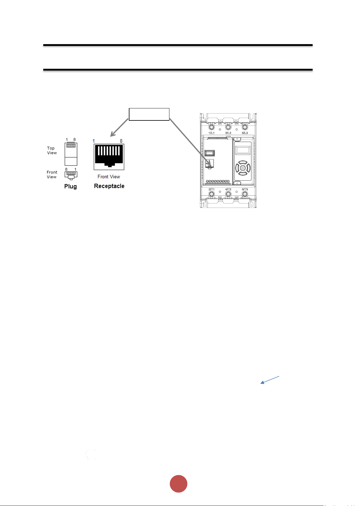
RJ45 Socket
Communication
CBL-036
CBL-035 Terminator
(last unit only)
PLC (Master)
PLC (Master)
The agilityTM units must have: a unique Modbus address on each unit
and identical Parity/Baud rate values on each unit
Modbus RTU Serial Communications
Modbus RTU Communications Interface
All agilityTM soft starts support Modbus RTU as standard. The RS-485 communications are accessible from
the RJ45 connector (see below).
1:
8: GND
* Warning: To avoid
damage to the unit
or to the RS-485
master, do NOT
connect to these
pins!
Not connected
2: Not connected
3: Not connected
4: TXD1-B-OUT
5: TXD0-A-OUT
6: Reserved*
7: Reserved*
Modbus RTU Connections
Single agilityTM RS-485 network
Multiple agilityTM RS-485 network
Page 41

40
agilityTM Series Soft Start User Manual
MAN-AGY-001. Version 04. 21/09/2018
Address
(1 byte)
Function
(1 byte)
Request Data (n
bytes)
CRC
(2 bytes)
Address
(1 byte)
Function
(1 byte)
Response Data
(n bytes)
CRC
(2 bytes)
Communication (continued)
Modbus Communications Configuration
The Modbus communication settings may be configured from the Device menu:
• Device >> Networks >> Modbus Network Settings >> Address (1 – 32)
• Device >> Networks >> Modbus Network Settings >> Baud (9600 – 115200)
• Device >> Networks >> Modbus Network Settings >> Parity (Odd / Even)
• (Data bits = 8, Stop bits = 1)
The communication parameters should be set before connecting the Modbus master.
Transmission Modes
ASCII and RTU transmission modes are defined in the Modbus protocol specification. agilityTM uses only the
RTU mode for the message transmission.
Message Structure For RTU Mode
The Modbus RTU structure uses a master-slave system for message exchange. In the case of the
agilityTM system, it allows up to 32 slaves, and one master. Every message begins with the master
making a request to a slave, which responds to the master in a defined structure. In both messages
(request and answer), the used structure is the same:
• Address, Function Code, Data and CRC.
Master (request message):
Slave (response message):
Address
The master initiates the communication by sending a byte with the address of the destination slave.
When responding, the slave also initiates the message with its own address. Broadcast to address 0
(zero) is not supported.
Function Code
This field contains a single byte, where the master specifies the type of service or function requested to
the slave (reading, writing, etc.). According to the protocol, each function is used to access a specific type
of data.
Data Field
The format and contents of this field depend on the function used and the transmitted value.
Page 42
41
agilityTM Series Soft Start User Manual
MAN-AGY-001. Version 04. 21/09/2018
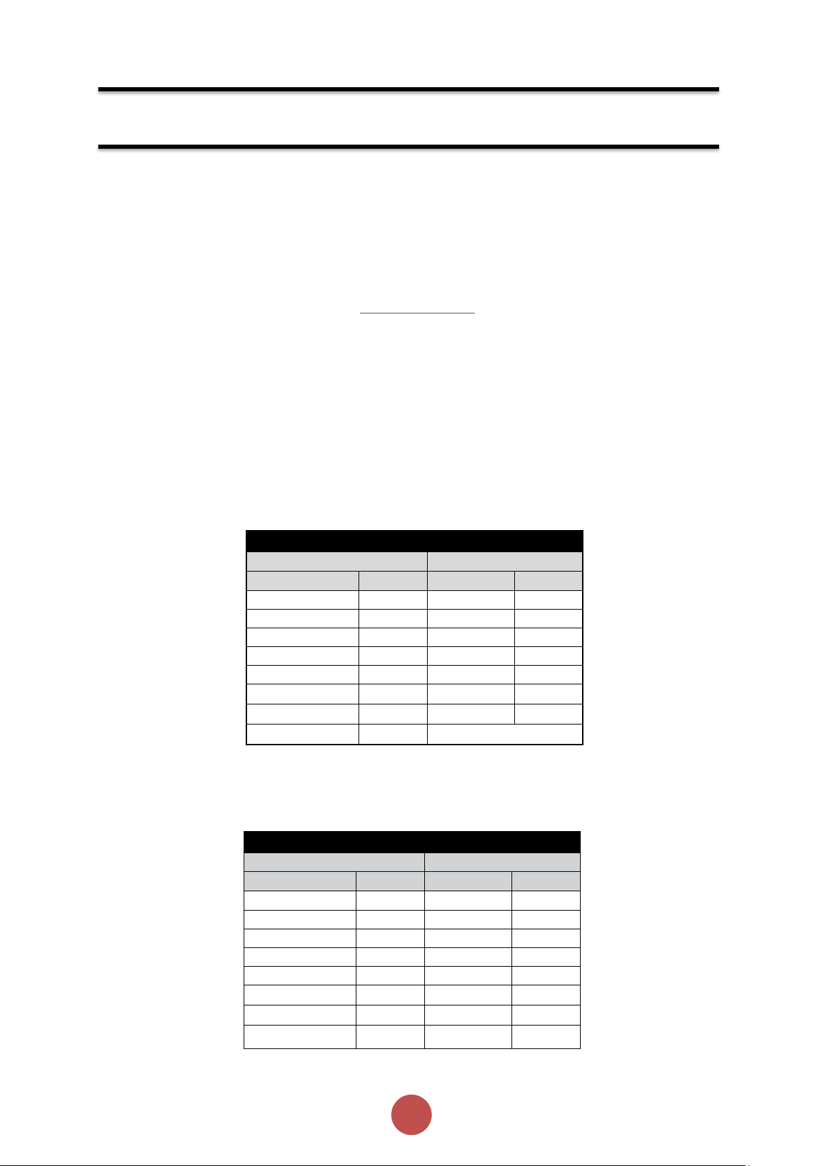
Modbus Function 03 Transaction Table
Query
Response
Field
Hex Byte
Field
Hex Byte
Slave address
01
Slave address
01
Function
03
Function
03
Start address Hi
00
Byte count
02
Start address Lo
01
Data Hi
01
No of registers
00
Data Lo
2C
No of registers
01
CRC Lo
B8
CRC Lo
D5
CRC Hi
09
CRC Hi
CA
Modbus Function 06 Transaction Table
Query
Response
Field
Hex Byte
Field
Hex Byte
Slave address
01
Slave address
01
Function
06
Function
06
Address Hi
00
Address Hi
02
Address Lo
0C
Address Lo
0C
Data Hi
00
Data Hi
00
Data Lo
09
Data Lo
09
CRC Lo
48
CRC Lo
88
CRC Hi
0C
CRC Hi
77
Communication (continued)
CRC
The used method is the CRC-16 (Cyclic Redundancy Check). This field is formed by two bytes; where first
the least significant byte is transmitted (CRC-), and then the most significant (CRC+). The CRC calculation
form is described in the Modbus RTU protocol specification.
Supported Functions
Modbus RTU specification defines the functions used to access different types of data.
•
agilityTM parameters are defined as holding type registers.
•
For Modbus RTU/TCP Client devices that use Modicon style addressing, place a 4 as the
high digit followed by the Modbus address defined in the parameter mapping table.
Note that agilityTM Modbus addressing starts at zero; not 1 as some devices do.
•
agilityTM 32-bit parameters are High Word / Low Word in Modbus format.
The following services are available:
Read Holding Registers
Description: reading register blocks of holding register type (block R/W limited to 8 registers).
•
Function code: 03 example
Write Single Register
Description: writing in a single register of the holding type.
•
Function code: 06 example
Page 43
42
agilityTM Series Soft Start User Manual
MAN-AGY-001. Version 04. 21/09/2018
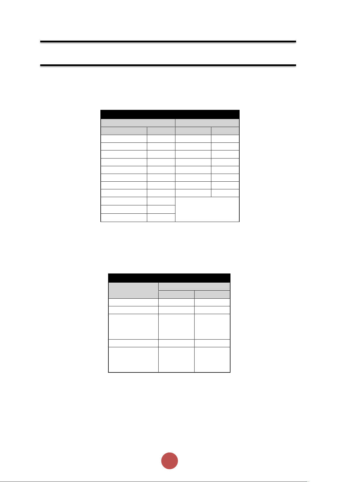
Modbus Address Memory Map
Parameter Modbus
Address
Modbus Data Address
Decimal
Hex
0000
0
0000h
0001
1
0001h
•
•
•
•
• • •
•
•
•
•
•
0128
128
0080h
•
•
•
•
• •
•
•
•
•
•
Modbus Function 16 Transaction Table
Query
Response
Field
Hex Byte
Field
Hex Byte
Slave address
01
Slave address
01
Function
10
Function
10
Address Hi
00
Address Hi
00
Address Lo
01
Address Lo
01
# Words Hi
00
# Words Hi
00
# Words Lo
01
# Words Lo
01
# Bytes
02
CRC Lo
50
Data Hi
00
CRC Hi
09
Data Lo
02
CRC Lo
26
CRC Hi
40
Communication (continued)
Write Multiple Registers
Description: writing register blocks of holding register type (block R/W limited to 8 registers).
• Function code: 16 example
Memory Map
agilityTM Modbus communication is based on reading or writing equipment parameters from or to the
holding registers. The data addressing is zero offset, such that the parameter Modbus address corresponds
to the register number.
Message Timing
In the RTU mode there is no specific start or stop byte that marks the beginning or the end of a
message. Indication of when a new message begins or when it ends is achieved by the absence of
data transmission for a minimum period of 3.5 times the transmission time of a data byte. Thus, in case a
message is transmitted after this minimum time has elapsed; the network elements will assume that the
first received character represents the beginning of a new message.
Page 44
43
agilityTM Series Soft Start User Manual
MAN-AGY-001. Version 04. 21/09/2018
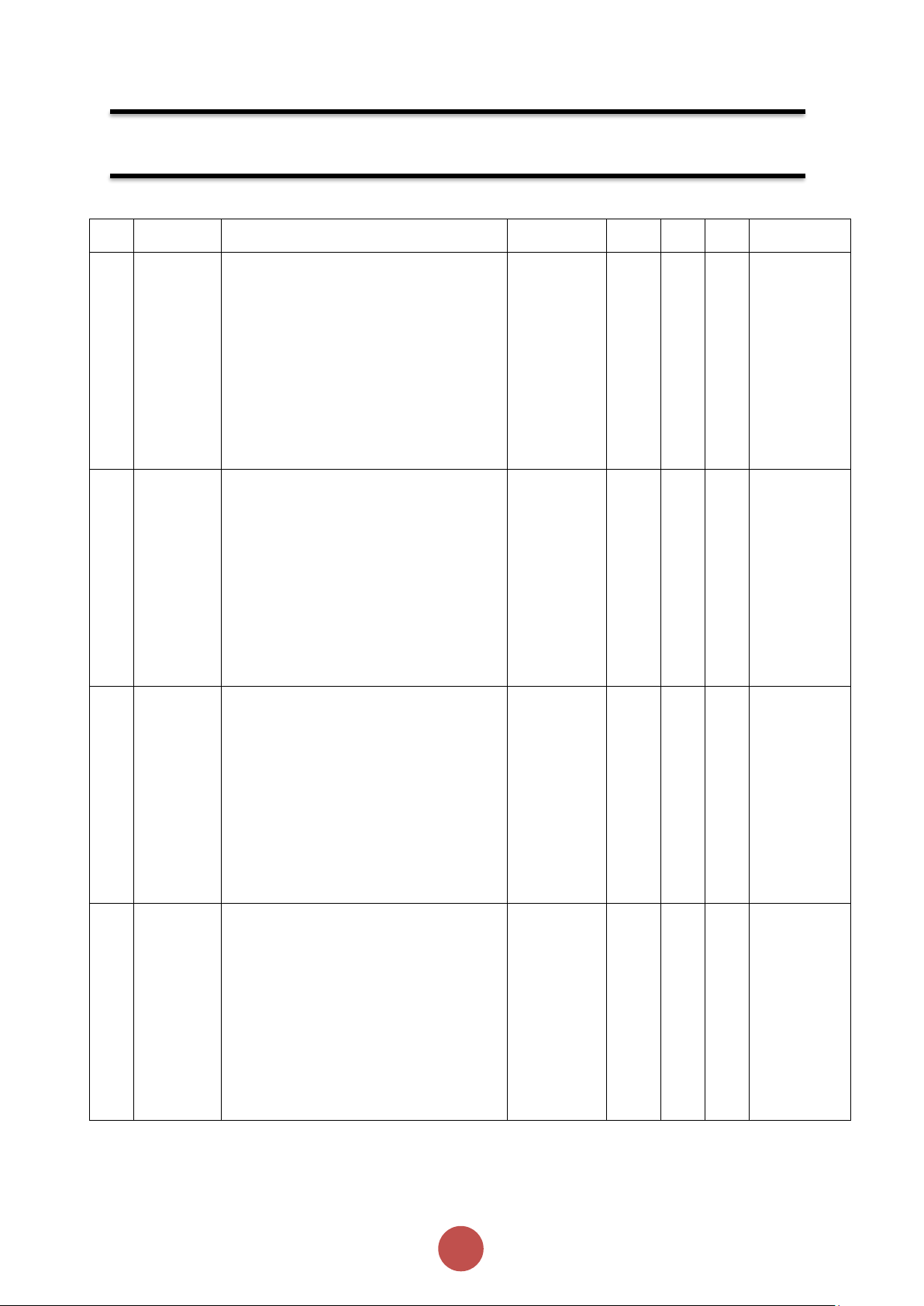
PNU
Name
Description
Options
Words
Type
Units
Detail
1
Cntrl
Mode
Selects the method for starting and
controlling the motor
Local : Control using the button on the
keypad
Remote : Control using the terminals.
Modbus : Control via Modbus network
0=Local,
1=Remote,
2=Modbus.
1
R/W Multiplier: 1
Divisor:1
Offset: 0
Min: 0
Max: 2
Default: 0
2
Initial
Volts
Percentage of the supply voltage applied
to motor at the beginning of the soft
start.
Increase to provide more torque If the
load fails to break away.
Decrease if the motor accelerates too
quickly.
1
R/W % Multiplier:
100
Divisor:1638
4
Offset: 0
Min: 1638
Max: 13107
Default:
3277
4
Start Time
Time taken to soft start from the "Initial
Volts" to the end of the start
Normally set between 5 and 30 seconds.
Actual time to get to full voltage
depends on the "Limit Amps".
If set too long the motor can be at speed
before the end of the time set.
1
R/W s Multiplier: 1
Divisor:1
Offset: 0
Min: 1
Max: 30
Default: 10
5
Stop Time
The time taken to soft stop from full
voltage to the end of the stop
Normally set between 15 and 30
seconds.
Actual time to get to the final voltage
depends on the "Limit Amps".
If set too long the motor may reach zero
speed before the end of the time set.
1
R/W s Multiplier: 1
Divisor:1
Offset: 0
Min: 0
Max: 30
Default: 0
Modbus RTU Parameters
Page 45

44
agilityTM Series Soft Start User Manual
MAN-AGY-001. Version 04. 21/09/2018
PNU
Name
Description
Options
Words
Type
Units
Detail
6
Start
Delay
Time allowed for external contactors to
close.
Increase if contactors are driven by
buffer relays or motor trips on phase
loss when start signal applied
Decrease if response to start signal
needs to be improved
1
R/W
ms
Multiplier: 1
Divisor:1
Offset: 0
Min: 100
Max: 30000
Default: 160
7
Serial No
The device serial number stored at the
point of manufacture
4
R Multiplier: 1
Divisor:1
Offset: 0
Min: 0
Max: 255
Default: 0
11
Model No
The device Model number stored at the
point of manufacture
1
R Multiplier: 1
Divisor:1
Offset: 0
Min: 101
Max: 113
Default: 101
14
Version
Software Version for the Main control
PCB
Software version recorded in log file
2
R Multiplier: 1
Divisor:1
Offset: 0
Min: 0
Max: 65535
Default: 0
Modbus RTU Parameters (continued)
Page 46

45
agilityTM Series Soft Start User Manual
MAN-AGY-001. Version 04. 21/09/2018
PNU
Name
Description
Options
Words
Type
Units
Detail
16
Application
The Unit has numerous pre-set
applications built in as standard.
Select the application best suited to the
load.
The selected application will
automatically change several
parameters and functions.
Depending on the application loaded
the “Trip Class" may also change
Refer to the separate 'applications
section' for more details
See Table 1
1
R/W Multiplier: 1
Divisor:1
Offset: 0
Min: 0
Max: 23
Default: 0
17
Trip Class
The trip class is a numeric value that
correlates the trip time with overload
level.
Select Trip class according to
application requirements
The trip time depends on the selected
"Trip Class" the duration of the
overload and the level of the over
current.
Refer to the Motor Overload 'cold' trip
curves given in the Guide.
When "Class 20" or "Class30" are
selected the Unit current rating (Unit
Amps) will be reduced to a lower value
(Rated Amps).
10=Class10,
20=Class20,
30=Class30.
1
R/W Multiplier: 1
Divisor:1
Offset: 0
Min: 10
Max: 30
Default: 10
18
Motor
Amps
This should be set to the Full Load
Current shown on the motor plate
The overload works with multiples of
the set "Motor Amps"
Also referred to as Motor FLA
2
R/W A Multiplier: 1
Divisor:1000
Offset: 0
Min: 0.1 x
PNU18
Max: 1 x
PNU20
Default: 1 x
PNU20
19
Reserved
--
Multiplier:
Divisor:
Offset:
Min:
Max:
Default:
Modbus RTU Parameters (continued)
Page 47

46
agilityTM Series Soft Start User Manual
MAN-AGY-001. Version 04. 21/09/2018
PNU
Name
Description
Options
Words
Type
Units
Detail
20
Rated
Amps
Unit Class20 / Class30 Current Rating
2 R A
Multiplier: 1
Divisor:1000
Offset: 0
Min: 17000
Max: 66000
Default:
17000
22
Unit Amps
Unit Class10 Current Rating
2 R A
Multiplier: 1
Divisor:1000
Offset: 0
Min: 17000
Max: 66000
Default:
17000
24
MotorState
Indicates the Unit Operating State
See Table 2
1
R Multiplier: 1
Divisor:1
Offset: 0
Min: 0
Max: 65535
Default: 0
25
I rms
The RMS motor current
This is the average of the 3 phases.
This value is used for the current Limit
and overload features
2 R A
Multiplier: 1
Divisor:1000
Offset: 0
Min: 0
Max: 24
Default: 0
Modbus RTU Parameters (continued)
Page 48
47
agilityTM Series Soft Start User Manual
MAN-AGY-001. Version 04. 21/09/2018
PNU
Name
Description
Options
Words
Type
Units
Detail
27
Overload
The Unit has an "Overload" function that
is an electronic equivalent to a thermal
overload.
Overload displays the overload capacity
which is a measure of how close the Unit
to tripping on "Overload Trip"
When "Irms" is greater than the
"Overload Amps" the "Overload"
increases in accordance with the "Trip
Class".
When "Current Irms" is less than
"Overload Level" the "Overload"
decreases exponentially (if greater than
50%)
When the "Overload" reaches 100% the
Unit will trip.
During situations when "Motor Amps" is
equal to "Unit Amps" the overload will
indicate 50%
1 R %
Multiplier: 100
Divisor:16384
Offset: 0
Min: 0
Max: 16384
Default: 0
During
situations
when "Motor
Amps" is equal
to "Unit Amps"
the overload
will indicate
50%
30
Frequency
The frequency of the 3-phase supply
1 R Hz
Multiplier: 1
Divisor:1000
Offset: 0
Min: 45000
Max: 65000
Default: 0
31
Factory Rst
Restores the Unit to the factory defaults
0=Idle,
1=Active.
1
R/W Multiplier: 1
Divisor:1
Offset: 0
Min: 0
Max: 1
Default: 0
Modbus RTU Parameters (continued)
Page 49
48
agilityTM Series Soft Start User Manual
MAN-AGY-001. Version 04. 21/09/2018
PNU
Name
Description
Options
Words
Type
Units
Detail
32
Store Param
Saves all Read /Write parameters to nonvolatile memory
Yes: Parameters are permanently written
No : Parameters remain changed until next
power cycle
0=Idle,
1=Active.
1
R/W Multiplier: 1
Divisor:1
Offset: 0
Min: 0
Max: 1
Default: 0
33
Save Log
Download the full log file on to the USB
stick
The Unit logs several parameters during
normal and fault conditions
Data is stored in CSV format. Please send
all downloaded files to Fairford on request
0=Idle,
1=Active.
1
R/W Multiplier: 1
Divisor:1
Offset: 0
Min: 0
Max: 1
Default: 0
34
Date
Enter current date
Date format can be set to either
dd/mm/yyyy or mm/dd/yyyy. Refer to
"Date format" parameter.
1
R/W Multiplier: 1
Divisor:1
Offset: 0
Min: 0
Max: 65535
Default: 0
35
Time
Allows the time to be changed to 'local'
time
By default the time is set to GMT
2
R/W Multiplier: 1
Divisor:1
Offset: 0
Min: 0
Max: 65535
Default: 0
Modbus RTU Parameters (continued)
Page 50
49
agilityTM Series Soft Start User Manual
MAN-AGY-001. Version 04. 21/09/2018
PNU
Name
Description
Options
Words
Type
Units
Detail
37
Rotation
Indicates the phase sequence of the
incoming supply.
RYB = ABC = L1-L2-L3
RBY = ACB = L1-L3-L2
0=------,
1=L1L2L3,
2=L1L3L2.
1
R Multiplier: 1
Divisor:1
Offset: 0
Min: 0
Max: 2
Default: 0
39
HS Temp C
The temperature of the internal Unit
heatsink.
The Unit will trip when the heatsink
temperature exceeds 80°C.
The internal cooling fans will turn on if this
temperature exceeds 40°C
1 R C
Multiplier: 1
Divisor:16
Offset: 0
Min: 0
Max: 65535
Default: 0
40
HS Temp F
The temperature of the internal Unit
heatsink.
The Unit will trip when the heatsink
temperature exceeds 176°C
The internal cooling fans will turn on if this
temperature exceeds 104°F
1 R F
Multiplier: 9
Divisor:80
Offset: 32
Min: 0
Max: 65535
Default: 0
41
I1 rms
The RMS current on phase L1
2 R A
Multiplier: 1
Divisor:1000
Offset: 0
Min: 0
Max: 24
Default: 0
Modbus RTU Parameters (continued)
Page 51
50
agilityTM Series Soft Start User Manual
MAN-AGY-001. Version 04. 21/09/2018
PNU
Name
Description
Options
Words
Type
Units
Detail
43
I2 rms
The RMS current on phase L2
2 R A
Multiplier: 1
Divisor:1000
Offset: 0
Min: 0
Max: 24
Default: 0
45
I3 rms
The RMS current on phase L3
2 R A
Multiplier: 1
Divisor:1000
Offset: 0
Min: 0
Max: 24
Default: 0
47
Delay Angle
Internal firing delay angle in Degrees
Displayed for diagnostic purposes
1 R °
Multiplier: 1
Divisor:1
Offset: 0
Min: 0
Max: 180
Default: 0
48
AGY100 Ver
The hardware version for display PCB
1
R Multiplier: 1
Divisor:1
Offset: 0
Min: 0
Max: 65535
Default: 1
Page 52

51
agilityTM Series Soft Start User Manual
MAN-AGY-001. Version 04. 21/09/2018
PNU
Name
Description
Options
Words
Type
Units
Detail
49
Phase Loss
Detects for various issues when the start
signal is applied
Detects for input phase loss / input phase
relationship / motor side loss
Trip On: Trips if there is an input phase loss
/ supply out of balance / motor side loss
Trip Off: The Unit will attempt to run
although the operation may be erratic.
Operating with the Trip Off for prolonged
periods may result in SCR failure
0=Trip Off,
1=Trip On.
1
R/W Multiplier: 1
Divisor:1
Offset: 0
Min: 0
Max: 1
Default: 1
50
Overheat
Detects if the internal temperature sensor
has malfunctioned
Trip On: The Unit will trip if the internal
temperature sensor malfunctions
Trip Off : The Unit will continue to operate
even if the temperature sensor has
malfunctioned.
Operating with the Trip Off for prolonged
periods may result in SCR failure
0=Trip Off,
1=Trip On.
1
R/W Multiplier: 1
Divisor:1
Offset: 0
Min: 0
Max: 1
Default: 1
51
Ph / SCR
Detects for various issues when "Starting"
or " Stopping"
Detects for input phase loss / Output phase
loss / SCR misfire
Trip On: Trips if there is an input phase loss
/ motor side phase loss / SCR misfire
Trip Off: The Unit will attempt to run
although the operation may be erratic.
Operating with the Trip Off for prolonged
periods may result in SCR failure
0=Trip Off,
1=Trip On.
1
R/W Multiplier: 1
Divisor:1
Offset: 0
Min: 0
Max: 1
Default: 1
Page 53
52
agilityTM Series Soft Start User Manual
MAN-AGY-001. Version 04. 21/09/2018
PNU
Name
Description
Options
Words
Type
Units
Detail
58
I Low
This can be used to detect if the motor is
running lightly loaded.
Trip On: The Unit will trip. This feature is
not active during soft start and soft stop.
Trip Off: The Unit will continue to operate
regardless of motor current
0=Trip Off,
1=Trip On.
1
R/W Multiplier: 1
Divisor:1
Offset: 0
Min: 0
Max: 1
Default: 0
59
I Limit Start
Selects trip or continue if the current limit
has been active for too long
Trip On: The Unit will trip
Trip Off: The start will continue regardless
of the motor current level
0=Trip Off,
1=Trip On.
1
R/W Multiplier: 1
Divisor:1
Offset: 0
Min: 0
Max: 1
Default: 1
60
Overload
The Unit has an "Overload" function that is
an electronic equivalent to a thermal
overload.
Trip On: The Unit will trip when the
"Overload" capacity (Modbus PNU 27)
exceeds 100%
Trip Off: The Unit will continue to operate
regardless of motor current level
0=Trip Off,
1=Trip On.
1
R/W Multiplier: 1
Divisor:1
Offset: 0
Min: 0
Max: 1
Default: 1
61
Shearpin
The Shearpin is an electronic equivalent of
a mechanical Shearpin
Trip On: The Unit will trip. This feature is
not active during soft start and soft stop.
Trip Off: The Unit will continue to operate
regardless of motor current level
0=Trip Off,
1=Trip On.
1
R/W Multiplier: 1
Divisor:1
Offset: 0
Min: 0
Max: 1
Default: 1
Page 54
53
agilityTM Series Soft Start User Manual
MAN-AGY-001. Version 04. 21/09/2018
PNU
Name
Description
Options
Words
Type
Units
Detail
64
Comms
Detects if the communications bus has
failed or become inactive.
To keep the bus active there must be at
least one Modbus read or write (any PNU)
during the "Comms Time” period
(ModbusPNU 147)
Trip On: Communication trip enabled.
Trip Off: External Trip is disabled
0=Trip Off,
1=Trip On.
1
R/W Multiplier: 1
Divisor:1
Offset: 0
Min: 0
Max: 1
Default: 1
66
Remote
For safety reasons the Unit will trip during
some operations if the remote start signal
is active
Trip On: Trips if the remote start signal is
active when the Unit is powered up or a
reset is applied.
Trip Off: The Unit will not trip and may start
unexpectedly if the start signal is accidently
left active.
0=Trip Off,
1=Trip On.
1
R/W Multiplier: 1
Divisor:1
Offset: 0
Min: 0
Max: 1
Default: 1
67
CT Fault
Detects if the internal current sensors have
failed or reading a very low level.
Trip On: The Unit will trip if the internal
current sensors fail or the current
measured falls to a very low level
Trip Off: Will continue to operate even if
the sensor has failed. Measurements and
overload protection may be affected
0=Trip Off,
1=Trip On.
1
R/W Multiplier: 1
Divisor:1
Offset: 0
Min: 0
Max: 1
Default: 1
68
Operation 1
Detects if the Control Board has failed to
operate normally
Trip On: System Trip enabled.
Trip Off: System Trip disabled.
0=Trip Off,
1=Trip On.
1
R/W Multiplier: 1
Divisor:1
Offset: 0
Min: 0
Max: 1
Default: 1
Page 55
54
agilityTM Series Soft Start User Manual
MAN-AGY-001. Version 04. 21/09/2018
PNU
Name
Description
Options
Words
Type
Units
Detail
69
Limit Amps
The current in Amps at which the soft Start
ramp is held.
Normally set to 350% of motor FLC.
Increase if motor fails to accelerate at
required rate
The "Limit Amps" will affect actual time to
start.
If set too low the motor may not accelerate
to full speed.
2
R/W A Multiplier: 1
Divisor:1000
Offset: 0
Min: 0.5 x
PNU18
Max: 5 x
PNU20
Default: 3.5 x
PNU20
71
Limit Time
The maximum time allowed for the current
limit.
If the current limit is still active at the end of
this period the Unit will either 'Trip' or
'continue'
1
R/W s Multiplier: 1
Divisor:1
Offset: 0
Min: 1
Max: 60
Default: 30
72
Boot Ver
Software Version for the Bootloader
2
R Multiplier: 1
Divisor:1
Offset: 0
Min: 0
Max: 65535
Default: 0
74
Cntrl Funct
Allows the Digital inputs to be mapped to
different functions
Cntrl Mode must be set to "Remote"
Two Wire: D1 = Start (Reset) / Stop
Three Wire: D1 = Start (Reset) D2 = Stop
D2 Reset , D2 Hold , D2 Enable , D2 Fire :
D1= Start /Stop, D2 programmed as shown
0=Three Wire,
1=Two Wire,
2=D2 Reset,
3=D2 Hold,
4=D2 Enable,
5=D2 Fire.
1
R/W Multiplier: 1
Divisor:1
Offset: 0
Min: 0
Max: 5
Default: 0
Page 56
55
agilityTM Series Soft Start User Manual
MAN-AGY-001. Version 04. 21/09/2018
PNU
Name
Description
Options
Words
Type
Units
Detail
75
Op Mode
Allows the unit to operate with a single
phase motor
3 phase: Set to control a three phase motor
1 Phase: Set to control a single phase
motor
0=3 phase ,
1=1 phase.
1
R/W Multiplier: 1
Divisor:1
Offset: 0
Min: 0
Max: 1
Default: 0
77
Trip 0
Displays the last Fault trip
See Table 3
1
R Multiplier: 1
Divisor:1
Offset: 0
Min: 0
Max: 65535
Default: 0
78
Trip 1
Displays the last Fault trip -1
See Table 3
1
R Multiplier: 1
Divisor:1
Offset: 0
Min: 0
Max: 65535
Default: 0
79
Trip 2
Displays the last Fault trip -2
See Table 3
1
R Multiplier: 1
Divisor:1
Offset: 0
Min: 0
Max: 65535
Default: 0
Page 57
56
agilityTM Series Soft Start User Manual
MAN-AGY-001. Version 04. 21/09/2018
PNU
Name
Description
Options
Words
Type
Units
Detail
80
Trip 3
Displays the last Fault trip -3
See Table 3
1
R Multiplier: 1
Divisor:1
Offset: 0
Min: 0
Max: 65535
Default: 0
81
Trip 4
Displays the last Fault trip -4
See Table 3
1
R Multiplier: 1
Divisor:1
Offset: 0
Min: 0
Max: 65535
Default: 0
82
Trip 5
Displays the last Fault trip -5
See Table 3
1
R Multiplier: 1
Divisor:1
Offset: 0
Min: 0
Max: 65535
Default: 0
83
Trip 6
Displays the last Fault trip -6
See Table 3
1
R Multiplier: 1
Divisor:1
Offset: 0
Min: 0
Max: 65535
Default: 0
Page 58
57
agilityTM Series Soft Start User Manual
MAN-AGY-001. Version 04. 21/09/2018
PNU
Name
Description
Options
Words
Type
Units
Detail
84
Trip 7
Displays the last Fault trip -7
See Table 3
1
R Multiplier: 1
Divisor:1
Offset: 0
Min: 0
Max: 65535
Default: 0
85
Trip 8
Displays the last Fault trip -8
See Table 3
1
R Multiplier: 1
Divisor:1
Offset: 0
Min: 0
Max: 65535
Default: 0
86
MenuBuild
Menu Version
1 R Multiplier: 1
Divisor:1
Offset: 0
Min: 0
Max: 65535
Default: 0
87
Kick Level
Percentage of the supply voltage applied to
the motor during the ‘kick' period
Increase to provide more torque If the load
fails to break away.
Decrease if the motor accelerates too
quickly.
1
R/W % Multiplier: 100
Divisor:16384
Offset: 0
Min: 3277
Max: 13107
Default: 9830
Page 59
58
agilityTM Series Soft Start User Manual
MAN-AGY-001. Version 04. 21/09/2018
PNU
Name
Description
Options
Words
Type
Units
Detail
88
Kick Time
Time that the torque pulse is applied to
load
Increase to provide more torque If the load
fails to break away.
Decrease if the motor accelerates too
quickly.
1
R/W
ms
Multiplier: 1
Divisor:1
Offset: 0
Min: 100
Max: 2000
Default: 100
89
Kick Start
Applies a short duration torque pulse to
dislodge 'sticky' loads
On: The torque pulse is applied at start-up
when complete the torque drops to the
"Initial Volts"
Off: The initial starting torque is defined by
the "Initial Volts"
0=Off, 1=On.
1
R/W Multiplier: 1
Divisor:1
Offset: 0
Min: 0
Max: 1
Default: 0
90
To USB
Allows the user to save parameters
Downloads the parameters from the Unit
to the USB drive
Data is stored in CSV format.
0=Idle,
1=Active.
1
R/W Multiplier: 1
Divisor:1
Offset: 0
Min: 0
Max: 1
Default: 0
91
From USB
Allows the user to load parameters stored
on a USB flash drive
Uploads the parameters from the USB
drive to the Unit
Data is stored in CSV format.
0=Idle,
1=Active.
1
R/W Multiplier: 1
Divisor:1
Offset: 0
Min: 0
Max: 1
Default: 0
Page 60
59
agilityTM Series Soft Start User Manual
MAN-AGY-001. Version 04. 21/09/2018
PNU
Name
Description
Options
Words
Type
Units
Detail
94
I Start
Displays the peak current during the last
start.
1 R A
Multiplier: 1
Divisor:1
Offset: 0
Min: 0
Max: 528
Default: 0
95
T Start
Displays the time of the last start
1 R s
Multiplier: 1
Divisor:1
Offset: 0
Min: 0
Max: 90
Default: 0
96
I Stop
Displays the peak current during the last
stop.
1 R A
Multiplier: 1
Divisor:1
Offset: 0
Min: 0
Max: 528
Default: 0
97
T Stop
Displays the time of the last stop
1 R s
Multiplier: 1
Divisor:1
Offset: 0
Min: 0
Max: 90
Default: 0
Page 61
60
agilityTM Series Soft Start User Manual
MAN-AGY-001. Version 04. 21/09/2018
PNU
Name
Description
Options
Words
Type
Units
Detail
98
Total Events
The total number of events that have been
recorded in the log file
2
R Multiplier: 1
Divisor:1
Offset: 0
Min: 0
Max: 65535
Default: 0
103
AGY200 Ver
The hardware version for Main PCB
1
R Multiplier: 1
Divisor:1
Offset: 0
Min: 0
Max: 65535
Default: 1
104
AGY300 Ver
The hardware version for Power PCB
1
R Multiplier: 1
Divisor:1
Offset: 0
Min: 0
Max: 65535
Default: 1
106
Total Uc On
The total number times the start command
has been applied
2
R Multiplier: 1
Divisor:1
Offset: 0
Min: 0
Max: 65535
Default: 0
Page 62
61
agilityTM Series Soft Start User Manual
MAN-AGY-001. Version 04. 21/09/2018
PNU
Name
Description
Options
Words
Type
Units
Detail
109
Operation 2
Detects if the Control Board has failed to
operate normally
Trip On: System Trip enabled.
Trip Off: System Trip disabled.
0=Trip Off,
1=Trip On.
1
R/W Multiplier: 1
Divisor:1
Offset: 0
Min: 0
Max: 1
Default: 1
110
Rerate Key
The Key issued by Fairford to re rate the
unit to a different current rating
Use this parameter to enter the key
manually.
4
R/W Multiplier: 1
Divisor:1
Offset: 0
Min: 0
Max: 255
Default: 0
114
Shear Amps
The current in Amps that will cause a
"Shear Trip"
A trip will occur if the motor current is
greater than the "Shear Amps" for the
"Shear Time"
2
R/W A Multiplier: 1
Divisor:1000
Offset: 0
Min: 1 x PNU18
Max: 5 x
PNU22
Default: 3.5 x
PNU18
116
Shear TIme
The trip time for the Shearpin trip
A trip will occur if the motor current is
greater than the "Shear Amps" for the
"Shear Time"
1
R/W s Multiplier: 1
Divisor:1
Offset: 0
Min: 1
Max: 10
Default: 1
Page 63
62
agilityTM Series Soft Start User Manual
MAN-AGY-001. Version 04. 21/09/2018
PNU
Name
Description
Options
Words
Type
Units
Detail
119
Modbus
Enable
Enable using Modbus
On: The unit is enabled
Off: The unit is disabled
0=Off, 1=On.
1
R/W Multiplier: 1
Divisor:1
Offset: 0
Min: 0
Max: 1
Default: 0
120
Modbus
Start
Start / Stop using Modbus
On: Starts the Unit
Off: Stops or Soft stops the Unit
0=Off, 1=On.
1
R/W Multiplier: 1
Divisor:1
Offset: 0
Min: 0
Max: 1
Default: 0
121
Modbus
Reset
Reset using Modbus
On: The initial state required for a reset.
Off: The final state required for a reset.
To reset pulse high and then low
0=Off, 1=On.
1
R/W Multiplier: 1
Divisor:1
Offset: 0
Min: 0
Max: 1
Default: 0
143
Fire Mode
A special feature that allows the Unit to
operate with ALL of the trips OFF.
Set " Cntrl Funct" to "D2 Fire Mode”,
Enabled when D2 is high
Although the unit will keep running in this
mode it may become damaged.
In some instances the damage may inhibit
a subsequent starts
This is only to be used in an emergency
0=Off, 1=On.
1
R Multiplier: 1
Divisor:1
Offset: 0
Min: 0
Max: 1
Default: 0
Page 64
63
agilityTM Series Soft Start User Manual
MAN-AGY-001. Version 04. 21/09/2018
PNU
Name
Description
Options
Words
Type
Units
Detail
145
TempUnit
Selects °C or °F for displayed temperatures
°C: All displayed temperatures are °C
°F: All displayed temperatures are °F
0=°C, 1=°F.
1
R/W Multiplier: 1
Divisor:1
Offset: 0
Min: 0
Max: 1
Default: 0
146
Disp Time
Time for backlight on display
After the period set the back light on the
screen will turn off
To reactivate touch screen anywhere. To
disable set to 0
1
R/W s Multiplier: 1
Divisor:1
Offset: 0
Min: 0
Max: 7200
Default: 60
147
CommsTime
Communications trip Timeout period
To prevent a 'Communications Trip' (If
enabled) the bus must be kept active.
To keep the bus active there must be at
least one Modbus read or write (any PNU)
during the "Timeout ms” period
1
R/W
ms
Multiplier: 1
Divisor:1
Offset: 0
Min: 0
Max: 60000
Default: 5000
148
Address
Sets the Modbus station number
1
R/W Multiplier: 1
Divisor:1
Offset: 0
Min: 1
Max: 32
Default: 1
Page 65
64
agilityTM Series Soft Start User Manual
MAN-AGY-001. Version 04. 21/09/2018
PNU
Name
Description
Options
Words
Type
Units
Detail
149
Parity
Sets the serial communications parity bit
The available parity options are None Even
Odd
Also sets the stop bits. No parity uses 2
stop bits. Odd or even parity uses 1 stop bit
0=Odd,
1=Even.
1
R/W Multiplier: 1
Divisor:1
Offset: 0
Min: 0
Max: 1
Default: 1
150
Baud
Sets the serial communications baud rate
The available baud rates are 9600, 19200,
38400, 57600 or 115200
0=9600 baud,
1=19200 baud,
2=38400 baud,
3=57600 baud,
4=115200
baud.
1
R/W Multiplier: 1
Divisor:1
Offset: 0
Min: 0
Max: 2
Default: 1
151
DateFormat
Allows the date format to be changed
dd/mm/yy or mm/dd/yy or yy/mm/dd
0=dd/mm/yy,
1=mm/dd/yy,
2=yy/mm/dd.
1
R/W Multiplier: 1
Divisor:1
Offset: 0
Min: 0
Max: 2
Default: 1
153
AGY400 Ver
Displays the hardware version for the
temperature sense PCB
1
R Multiplier: 1
Divisor:1
Offset: 0
Min: 0
Max: 65535
Default: 1
Page 66
65
agilityTM Series Soft Start User Manual
MAN-AGY-001. Version 04. 21/09/2018
PNU
Name
Description
Options
Words
Type
Units
Detail
154
RelayFunct
Allows the n/c relay (21 -22) to be
reconfigured
Available options are 22 = TOR or 22 =
ERR
0=22 = TOR,
1=22 = ERR.
1
R/W Multiplier: 1
Divisor:1
Offset: 0
Min: 0
Max: 1
Default: 1
155
Reserved
No user function
157
Window View
Used to arrange the Modbus Parameters
into Groups
Refer to 'Special Modbus parameters'
document for more details
1
R/W Multiplier: 1
Divisor:1
Offset: 0
Min: 0
Max: 65535
Default: 0
158
Window
Code
Used to arrange the Modbus Parameters
into Groups
Refer to 'Special Modbus parameters'
document for more details
1
R/W Multiplier: 1
Divisor:1
Offset: 0
Min: 0
Max: 65535
Default: 0
Page 67
66
agilityTM Series Soft Start User Manual
MAN-AGY-001. Version 04. 21/09/2018
PNU
Name
Description
Options
Words
Type
Units
Detail
159
ODB Type
Reserved for future use
1
R Multiplier: 1
Divisor:1
Offset: 0
Min: 0
Max: 65535
Default: 1
160
Patch Addr 1
Used to arrange the Modbus Parameters
into Groups
Refer to 'Special Modbus parameters'
document for more details
1
R/W Multiplier: 1
Divisor:1
Offset: 0
Min: 0
Max: 65535
Default: 0
161
Patch Addr 2
Used to arrange the Modbus Parameters
into Groups
Refer to 'Special Modbus parameters'
document for more details
1
R/W Multiplier: 1
Divisor:1
Offset: 0
Min: 0
Max: 65535
Default: 0
162
Patch Addr 3
Used to arrange the Modbus Parameters
into Groups
Refer to 'Special Modbus parameters'
document for more details
1
R/W Multiplier: 1
Divisor:1
Offset: 0
Min: 0
Max: 65535
Default: 0
Page 68
67
agilityTM Series Soft Start User Manual
MAN-AGY-001. Version 04. 21/09/2018
PNU
Name
Description
Options
Words
Type
Units
Detail
163
Patch Addr 4
Used to arrange the Modbus Parameters
into Groups
Refer to 'Special Modbus parameters'
document for more details
1
R/W Multiplier: 1
Divisor:1
Offset: 0
Min: 0
Max: 65535
Default: 0
164
Patch Addr 5
Used to arrange the Modbus Parameters
into Groups
Refer to 'Special Modbus parameters'
document for more details
1
R/W Multiplier: 1
Divisor:1
Offset: 0
Min: 0
Max: 65535
Default: 0
165
Patch Addr 6
Used to arrange the Modbus Parameters
into Groups
Refer to 'Special Modbus parameters'
document for more details
1
R/W Multiplier: 1
Divisor:1
Offset: 0
Min: 0
Max: 65535
Default: 0
166
Patch Addr 7
Used to arrange the Modbus Parameters
into Groups
Refer to 'Special Modbus parameters'
document for more details
1
R/W Multiplier: 1
Divisor:1
Offset: 0
Min: 0
Max: 65535
Default: 0
Page 69
68
agilityTM Series Soft Start User Manual
MAN-AGY-001. Version 04. 21/09/2018
PNU
Name
Description
Options
Words
Type
Units
Detail
167
Patch Addr 8
Used to arrange the Modbus Parameters
into Groups
Refer to 'Special Modbus parameters'
document for more details
1
R/W Multiplier: 1
Divisor:1
Offset: 0
Min: 0
Max: 65535
Default: 0
168
Patch Addr 9
Used to arrange the Modbus Parameters
into Groups
Refer to 'Special Modbus parameters'
document for more details
1
R/W Multiplier: 1
Divisor:1
Offset: 0
Min: 0
Max: 65535
Default: 0
169
Patch Addr
10
Used to arrange the Modbus Parameters
into Groups
Refer to 'Special Modbus parameters'
document for more details
1
R/W Multiplier: 1
Divisor:1
Offset: 0
Min: 0
Max: 65535
Default: 0
170
Patch Addr
11
Used to arrange the Modbus Parameters
into Groups
Refer to 'Special Modbus parameters'
document for more details
1
R/W Multiplier: 1
Divisor:1
Offset: 0
Min: 0
Max: 65535
Default: 0
Page 70
69
agilityTM Series Soft Start User Manual
MAN-AGY-001. Version 04. 21/09/2018
PNU
Name
Description
Options
Words
Type
Units
Detail
171
Patch Addr
12
Used to arrange the Modbus Parameters
into Groups
Refer to 'Special Modbus parameters'
document for more details
1
R/W Multiplier: 1
Divisor:1
Offset: 0
Min: 0
Max: 65535
Default: 0
172
Patch Addr
13
Used to arrange the Modbus Parameters
into Groups
Refer to 'Special Modbus parameters'
document for more details
1
R/W Multiplier: 1
Divisor:1
Offset: 0
Min: 0
Max: 65535
Default: 0
173
Patch Addr
14
Used to arrange the Modbus Parameters
into Groups
Refer to 'Special Modbus parameters'
document for more details
1
R/W Multiplier: 1
Divisor:1
Offset: 0
Min: 0
Max: 65535
Default: 0
174
Patch Addr
15
Used to arrange the Modbus Parameters
into Groups
Refer to 'Special Modbus parameters'
document for more details
1
R/W Multiplier: 1
Divisor:1
Offset: 0
Min: 0
Max: 65535
Default: 0
Page 71
70
agilityTM Series Soft Start User Manual
MAN-AGY-001. Version 04. 21/09/2018
PNU
Name
Description
Options
Words
Type
Units
Detail
175
Patch Addr
16
Used to arrange the Modbus Parameters
into Groups
Refer to 'Special Modbus parameters'
document for more details
1
R/W Multiplier: 1
Divisor:1
Offset: 0
Min: 0
Max: 65535
Default: 0
176
Window 1
Used to arrange the Modbus Parameters
into Groups
Refer to 'Special Modbus parameters'
document for more details
1
R/W Multiplier: 1
Divisor:1
Offset: 0
Min: 0
Max: 65535
Default: 0
177
Window 2
Used to arrange the Modbus Parameters
into Groups
Refer to 'Special Modbus parameters'
document for more details
1
R/W Multiplier: 1
Divisor:1
Offset: 0
Min: 0
Max: 65535
Default: 0
178
Window 3
Used to arrange the Modbus Parameters
into Groups
Refer to 'Special Modbus parameters'
document for more details
1
R/W Multiplier: 1
Divisor:1
Offset: 0
Min: 0
Max: 65535
Default: 0
Page 72
71
agilityTM Series Soft Start User Manual
MAN-AGY-001. Version 04. 21/09/2018
PNU
Name
Description
Options
Words
Type
Units
Detail
179
Window 4
Used to arrange the Modbus Parameters
into Groups
Refer to 'Special Modbus parameters'
document for more details
1
R/W Multiplier: 1
Divisor:1
Offset: 0
Min: 0
Max: 65535
Default: 0
180
Window 5
Used to arrange the Modbus Parameters
into Groups
Refer to 'Special Modbus parameters'
document for more details
1
R/W Multiplier: 1
Divisor:1
Offset: 0
Min: 0
Max: 65535
Default: 0
181
Window 6
Used to arrange the Modbus Parameters
into Groups
Refer to 'Special Modbus parameters'
document for more details
1
R/W Multiplier: 1
Divisor:1
Offset: 0
Min: 0
Max: 65535
Default: 0
182
Window 7
Used to arrange the Modbus Parameters
into Groups
Refer to 'Special Modbus parameters'
document for more details
1
R/W Multiplier: 1
Divisor:1
Offset: 0
Min: 0
Max: 65535
Default: 0
Page 73
72
agilityTM Series Soft Start User Manual
MAN-AGY-001. Version 04. 21/09/2018
PNU
Name
Description
Options
Words
Type
Units
Detail
183
Window 8
Used to arrange the Modbus Parameters
into Groups
Refer to 'Special Modbus parameters'
document for more details
1
R/W Multiplier: 1
Divisor:1
Offset: 0
Min: 0
Max: 65535
Default: 0
184
Window 9
Used to arrange the Modbus Parameters
into Groups
Refer to 'Special Modbus parameters'
document for more details
1
R/W Multiplier: 1
Divisor:1
Offset: 0
Min: 0
Max: 65535
Default: 0
185
Window 10
Used to arrange the Modbus Parameters
into Groups
Refer to 'Special Modbus parameters'
document for more details
1
R/W Multiplier: 1
Divisor:1
Offset: 0
Min: 0
Max: 65535
Default: 0
186
Window 11
Used to arrange the Modbus Parameters
into Groups
Refer to 'Special Modbus parameters'
document for more details
1
R/W Multiplier: 1
Divisor:1
Offset: 0
Min: 0
Max: 65535
Default: 0
Page 74
73
agilityTM Series Soft Start User Manual
MAN-AGY-001. Version 04. 21/09/2018
PNU
Name
Description
Options
Words
Type
Units
Detail
187
Window 12
Used to arrange the Modbus Parameters
into Groups
Refer to 'Special Modbus parameters'
document for more details
1
R/W Multiplier: 1
Divisor:1
Offset: 0
Min: 0
Max: 65535
Default: 0
188
Window 13
Used to arrange the Modbus Parameters
into Groups
Refer to 'Special Modbus parameters'
document for more details
1
R/W Multiplier: 1
Divisor:1
Offset: 0
Min: 0
Max: 65535
Default: 0
189
Window 14
Used to arrange the Modbus Parameters
into Groups
Refer to 'Special Modbus parameters'
document for more details
1
R/W Multiplier: 1
Divisor:1
Offset: 0
Min: 0
Max: 65535
Default: 0
190
Window 15
Used to arrange the Modbus Parameters
into Groups
Refer to 'Special Modbus parameters'
document for more details
1
R/W Multiplier: 1
Divisor:1
Offset: 0
Min: 0
Max: 65535
Default: 0
Page 75
74
agilityTM Series Soft Start User Manual
MAN-AGY-001. Version 04. 21/09/2018
PNU
Name
Description
Options
Words
Type
Units
Detail
191
Window 16
Used to arrange the Modbus Parameters
into Groups
Refer to 'Special Modbus parameters'
document for more details
1
R/W Multiplier: 1
Divisor:1
Offset: 0
Min: 0
Max: 65535
Default: 0
192
Window 17
Used to arrange the Modbus Parameters
into Groups
Refer to 'Special Modbus parameters'
document for more details
1
R/W Multiplier: 1
Divisor:1
Offset: 0
Min: 0
Max: 65535
Default: 0
193
Window 18
Used to arrange the Modbus Parameters
into Groups
Refer to 'Special Modbus parameters'
document for more details
1
R/W Multiplier: 1
Divisor:1
Offset: 0
Min: 0
Max: 65535
Default: 0
194
Window 19
Used to arrange the Modbus Parameters
into Groups
Refer to 'Special Modbus parameters'
document for more details
1
R/W Multiplier: 1
Divisor:1
Offset: 0
Min: 0
Max: 65535
Default: 0
Page 76

75
agilityTM Series Soft Start User Manual
MAN-AGY-001. Version 04. 21/09/2018
PNU
Name
Description
Options
Words
Type
Units
Detail
195
Window 20
Used to arrange the Modbus Parameters
into Groups
Refer to 'Special Modbus parameters'
document for more details
1
R/W Multiplier: 1
Divisor:1
Offset: 0
Min: 0
Max: 65535
Default: 0
196
Window 21
Used to arrange the Modbus Parameters
into Groups
Refer to 'Special Modbus parameters'
document for more details
1
R/W Multiplier: 1
Divisor:1
Offset: 0
Min: 0
Max: 65535
Default: 0
197
Window 22
Used to arrange the Modbus Parameters
into Groups
Refer to 'Special Modbus parameters'
document for more details
1
R/W Multiplier: 1
Divisor:1
Offset: 0
Min: 0
Max: 65535
Default: 0
198
Window 23
Used to arrange the Modbus Parameters
into Groups
Refer to 'Special Modbus parameters'
document for more details
1
R/W Multiplier: 1
Divisor:1
Offset: 0
Min: 0
Max: 65535
Default: 0
Page 77
76
agilityTM Series Soft Start User Manual
MAN-AGY-001. Version 04. 21/09/2018
PNU
Name
Description
Options
Words
Type
Units
Detail
199
Window 24
Used to arrange the Modbus Parameters
into Groups
Refer to 'Special Modbus parameters'
document for more details
1
R/W Multiplier: 1
Divisor:1
Offset: 0
Min: 0
Max: 65535
Default: 0
200
Total Us On
The total number of times the unit has
been powered up.
The unit is powered up by applying a
voltage to Uc
Uc will be 24V or 110V / 230V depending on
configuration
2
R Multiplier: 1
Divisor:1
Offset: 0
Min: 0
Max: 65535
Default: 0
202
Total Us Off
The total number of times the unit has
been powered down.
The unit is powered down by removing the
voltage at Uc
Uc will be 24V or 110V / 230V depending on
configuration
2
R Multiplier: 1
Divisor:1
Offset: 0
Min: 0
Max: 65535
Default: 0
204
Total Runs
The total number of times the unit as
successfully got to the "Running" State
The Running state is active when the unit is
operating at full voltage.
When operating at full voltage the internal
bypass relays are closed.
2
R Multiplier: 1
Divisor:1
Offset: 0
Min: 0
Max: 65535
Default: 0
Page 78
77
agilityTM Series Soft Start User Manual
MAN-AGY-001. Version 04. 21/09/2018
PNU
Name
Description
Options
Words
Type
Units
Detail
206
Total Stops
The total number of successful stops / soft
stops
2
R Multiplier: 1
Divisor:1
Offset: 0
Min: 0
Max: 65535
Default: 0
210
Total Trips
The total number of trips
2
R Multiplier: 1
Divisor:1
Offset: 0
Min: 0
Max: 65535
Default: 0
211
Reserved
Multiplier:
Divisor:
Offset:
Min:
Max:
Default:
212
Diagnostic 1
Used for diagnostic purposes only
1
R/W Multiplier: 1
Divisor:1
Offset: 0
Min: 0
Max: 65535
Default: 65535
Page 79
78
agilityTM Series Soft Start User Manual
MAN-AGY-001. Version 04. 21/09/2018
PNU
Name
Description
Options
Words
Type
Units
Detail
213
Diagnostic 2
Used for diagnostic purposes only
1
R/W Multiplier: 1
Divisor:1
Offset: 0
Min: 0
Max: 65535
Default: 65535
214
Diagnostic 3
Used for diagnostic purposes only
1
R/W Multiplier: 1
Divisor:1
Offset: 0
Min: 0
Max: 65535
Default: 65535
215
Diagnostic 4
Used for diagnostic purposes only
1
R/W Multiplier: 1
Divisor:1
Offset: 0
Min: 0
Max: 65535
Default: 65535
216
Diagnostic 5
Used for diagnostic purposes only
1
R/W Multiplier: 1
Divisor:1
Offset: 0
Min: 0
Max: 65535
Default: 65535
Page 80
79
agilityTM Series Soft Start User Manual
MAN-AGY-001. Version 04. 21/09/2018
PNU
Name
Description
Options
Words
Type
Units
Detail
217
Diagnostic 6
Used for diagnostic purposes only
1
R/W Multiplier: 1
Divisor:1
Offset: 0
Min: 0
Max: 65535
Default: 65535
218
Ovld Amps
Determines the level in Amps at which the
overload will start.
Normally set to 115% of the set "Motor
Amps"
Reduce to speed up trip response
2
R/W A Multiplier: 1
Divisor:1000
Offset: 0
Min: 1 x PNU18
Max: 1.25 x
PNU18
Default: 1.15 x
PNU18
220
Language
Selects the display language for the keypad
Enter the required language from the
displayed list
1=English,
2=Deutsch,
3=Francais,
4=Italiano,
5=Portugues,
6=Espanol.
1
R/W Multiplier: 1
Divisor:1
Offset: 0
Min: 1
Max: 10
Default: 1
221
Total Starts
The total number of successful starts
2
R Multiplier: 1
Divisor:1
Offset: 0
Min: 0
Max: 65535
Default: 0
Page 81
80
agilityTM Series Soft Start User Manual
MAN-AGY-001. Version 04. 21/09/2018
PNU
Name
Description
Options
Words
Type
Units
Detail
223
L1L2L3
Determines if supply phase sequence is
incorrect for motor rotation
On: Trips if the phase sequence is L1-L2-L3.
Off: The Unit will continue to operate
normally
0=Trip Off,
1=Trip On.
1
R/W Multiplier: 1
Divisor:1
Offset: 0
Min: 0
Max: 1
Default: 0
224
L1L3L2
Determines if supply phase sequence is
incorrect for motor rotation
On: Trips if the phase sequence is L1-L3-L2.
Off: The Unit will continue to operate
normally
0=Trip Off,
1=Trip On.
1
R/W Multiplier: 1
Divisor:1
Offset: 0
Min: 0
Max: 1
Default: 0
225
RX Bytes
Diagnostic parameter for Modbus
communications
Indicates transmission bytes are being
received
1
R Multiplier: 1
Divisor:1
Offset: 0
Min: 0
Max: 65535
Default: 0
226
RX Frames
Diagnostic parameter for Modbus
communications
Indicates transmission frames are being
received
1
R Multiplier: 1
Divisor:1
Offset: 0
Min: 0
Max: 65535
Default: 0
Page 82
81
agilityTM Series Soft Start User Manual
MAN-AGY-001. Version 04. 21/09/2018
PNU
Name
Description
Options
Words
Type
Units
Detail
227
RX Errors
Diagnostic parameter for Modbus
communications
Indicates whether the data has errors
1
R Multiplier: 1
Divisor:1
Offset: 0
Min: 0
Max: 65535
Default: 0
228
RX TMO Er
Diagnostic parameter for Modbus
communications
Indicates a timing error
1
R Multiplier: 1
Divisor:1
Offset: 0
Min: 0
Max: 65535
Default: 0
229
TX Bytes
Diagnostic parameter for Modbus
communications
Indicates transmission bytes are being sent
1
R Multiplier: 1
Divisor:1
Offset: 0
Min: 0
Max: 65535
Default: 0
230
TX Frames
Diagnostic parameter for Modbus
communications
Indicates transmission frames are being
sent
1
R Multiplier: 1
Divisor:1
Offset: 0
Min: 0
Max: 65535
Default: 0
Page 83
82
agilityTM Series Soft Start User Manual
MAN-AGY-001. Version 04. 21/09/2018
PNU
Name
Description
Options
Words
Type
Units
Detail
231
TX Errors
Diagnostic parameter for Modbus
communications
Indicates whether the data has errors
1
R Multiplier: 1
Divisor:1
Offset: 0
Min: 0
Max: 65535
Default: 0
232
StopCode
File
Diagnostic parameter
For Fairford use only
1
R Multiplier: 1
Divisor:1
Offset: 0
Min: 0
Max: 65535
Default: 65535
233
StopCode
File_1
Diagnostic parameter
For Fairford use only
1
R Multiplier: 1
Divisor:1
Offset: 0
Min: 0
Max: 65535
Default: 65535
234
StopCode
Pos
Diagnostic parameter
For Fairford use only
1
R Multiplier: 1
Divisor:1
Offset: 0
Min: 0
Max: 65535
Default: 65535
Page 84
83
agilityTM Series Soft Start User Manual
MAN-AGY-001. Version 04. 21/09/2018
PNU
Name
Description
Options
Words
Type
Units
Detail
235
StopCode
Pos_1
Diagnostic parameter
For Fairford use only
1
R Multiplier: 1
Divisor:1
Offset: 0
Min: 0
Max: 65535
Default: 65535
236
Limit Amps
The current in Amps at which the soft stop
ramp is not allowed to go above.
Normally set to 350% motor FLC. Increase if
motor decelerates too rapidly.
The current limit level will affect actual time
to stop the motor.
2
R/W A Multiplier: 1
Divisor:1000
Offset: 0
Min: 0.5 x
PNU18
Max: 5 x
PNU20
Default: 5 x
PNU20
238
Limit Time
The maximum time allowed for the current
limit.
If the current limit is still active at the end of
this period the Unit will either trip or
continue
1
R/W s Multiplier: 1
Divisor:1
Offset: 0
Min: 1
Max: 60
Default: 2
239
I Low Amps
The current in Amps that will cause a trip
A trip will occur if the motor current is less
than the "I Low Amps" level for the "I Low
Time"
2
R/W A Multiplier: 1
Divisor:1000
Offset: 0
Min: 0.25 x
PNU18
Max: 1 x
PNU18
Default: 0.25 x
PNU18
Page 85
84
agilityTM Series Soft Start User Manual
MAN-AGY-001. Version 04. 21/09/2018
PNU
Name
Description
Options
Words
Type
Units
Detail
241
I Low Time
The trip time for the Low current trip
A trip will occur if the motor current is less
than the "I Low Amps" level for the "I Low
Time"
1
R/W s Multiplier: 1
Divisor:1
Offset: 0
Min: 1
Max: 60
Default: 30
242
I Limit Stop
Selects trip or continue if the current limit
has been active for too long
Trip On: The Unit will trip
Trip Off: The stop will continue regardless
of the motor current level
0=Trip Off,
1=Trip On.
1
R/W Multiplier: 1
Divisor:1
Offset: 0
Min: 0
Max: 1
Default: 0
243
Keypad Pwr
Connects the 24V dc supply a pin on the
RJ45 connector.
Must be turned "On" if the remote keypad
is connected
0=Off, 1=On.
1
R/W Multiplier: 1
Divisor:1
Offset: 0
Min: 0
Max: 1
Default: 0
244
Service No
Diagnostic parameter
For Fairford use only
1
R/W Multiplier: 1
Divisor:1
Offset: 0
Min: 0
Max: 65535
Default: 0
Page 86
85
agilityTM Series Soft Start User Manual
MAN-AGY-001. Version 04. 21/09/2018
PNU
Name
Description
Options
Words
Type
Units
Detail
245
Scroll
Used to allow the text to scroll on the
keypad
On: If the text is too long for the display it
will scroll
Off: If the text is too long for the display the
message will be truncated
0=Off, 1=On.
1
R/W Multiplier: 1
Divisor:1
Offset: 0
Min: 0
Max: 1
Default: 1
246
Reset Ovld
Factory parameter
Fairford use only
0=Off, 1=On.
1
R/W Multiplier: 1
Divisor:1
Offset: 0
Min: 0
Max: 1
Default: 0
247
StartsHr
When the fan is connected the number of
fully rated starts can be increased
Without the fan connected the number of
fully rated starts is 5
With the fan connected the number of fully
rated starts is 40
1
R Multiplier: 1
Divisor:1
Offset: 0
Min: 0
Max: 65535
Default: 0
248
Initial Deg C
Displays the temperature of the heatsink at
the beginning of the start
1 R C
Multiplier: 1
Divisor:1
Offset: 0
Min: 0
Max: 65535
Default: 0
Page 87
86
agilityTM Series Soft Start User Manual
MAN-AGY-001. Version 04. 21/09/2018
Table 1
PNU 16 Value
Auto Application
0
Default
1
Heavy
2
Agitator
3
Compressor 1
4
Compressor 2
5
Conveyor Loaded
6
Conveyor Unloaded
7
Crusher
8
Fan High Inertia
9
Fan Low Inertia
10
Grinder
11
Mill
12
Mixer
13
Moulding M/C
14
Press Flywheel
15
Pump 1
16
Pump 2
17
PumpJack
18
Saw-Band
19
Saw-Circular
20
Screen Vibrating
21
Shredder
22
Woodchipper.
Table 2
PNU 24 Value
Status
20
Starting
22
Fire Mode
25
Limit Start
35
Limit Stop
40
Stopping
60
Running
128
Ready
140
Tripped
200
Disabled
250
Initialisation
Page 88
87
agilityTM Series Soft Start User Manual
MAN-AGY-001. Version 04. 21/09/2018
Table 3
PNU 78 thru 85
Trip Status
100
Ph Loss
200
Thermal
300
Ph / SCR
400
Mot Side
500
Freq
600
Uc Low
700
SCR Sen
800
Fan
1000
SCR S/C
1100
Low Amp
1200
Limit
1300
Overload
1400
Shear
1500
PTC
1600
External
1700
Comms
1800
Bypass
1900
FireMode
2000
Remote
2100
Rotation
2200
Op1
2300
CT Fault
1100
Op2 Pnu
1200
Op2 Mod
13000
Op2 Mon
14000
Op2 Men
15000
Op2 Keys
16000
Op2 Motr
17000
Op2 Log
18000
Op2 Disk.
Page 89
88
agilityTM Series Soft Start User Manual
MAN-AGY-001. Version 04. 21/09/2018
Register Name
Reg ID
Description
Window View
157
Selects what is viewed through the window
0 – Patched Registers
1 – Log Records
Window Code
158
Log Record function
0 – None
1 – Report
2 – Rewind
3 – Unwind
4 – Seek Absolute
5 – Seek Relative
6 – Next Record
16 – Auto Increment
Reserved
159
For future functionality.
Patch Address 1 to 16
160 to 175
16 place holders for the registers that need to be
patched
Window 1 to 24
176 to 199
Either: If Window View set to 0
16 data holders related to the selected addresses in
the Patch Address section (in Window 1 to 16 only).
Or
For Window View set to 1
All 24 words to hold the currently select log record
Special Modbus Registers
List of special Modbus registers, descriptions, and usage.
Window registers section
There is a section of Modbus registers that can be used for special (user programable) purposes.
Currently there are two uses for this group of Modbus registers.
1) Register patching.
Register patching is enabled when the Window View register (157) is set a to Patched
Registers (0).
It allows the user to patch (re-map) a selection of disparate registers into a contiguous
register section or window, so that retrieval of the most requested data can be handled
in more efficient single block reads by a host controller (PLC). When the address of a
register is placed in the Patch Address section (160 to 175) then the corresponding
Page 90
89
agilityTM Series Soft Start User Manual
MAN-AGY-001. Version 04. 21/09/2018
Register
Name
Register
Number
Register
Value
Patch
Register
Patch
Value
Window
Register
Window
Value
Motor State
24
128 160
24
176
128
Register
Name
Register
Number
Register
Value
Patch
Register
Patch
Value
Window
Register
Window
Value
Unit Amps
22 0
160
22
176
0
5500
161
23 0r 0
177
5500
Register
Name
Register
Number
Register
Value
Patch
Register
Patch
Value
Window
Register
Window
Value
Serial
Number
7
0x0041
160 7 176
0x0041
0x3132
161
8 or 0
177
0x3132
0x3334
162
9 or 0
178
0x3334
0x3536
163
10 or 0
179
0x3536
Motor State
24
128 164
24
180
128
Unit Amps
22 0
165
22
181
0
5500
167
23 0r 0
182
5500
WORD(s) in the Window section (176 to 192) will mirror the data and function of that
register.
For example, if register 24 (Motor State) is set into register 160 (Patch Address 1) then the
value report in 176 (Window 1) from then on.
Consideration needs to be given to registers that produce multiple WORD data. For
example, 22 (Unit Amps) produces a 32 bit or 2 WORD datum. To mirror both of those
WORDs into the Window both registers 22 and 23 will need to be assigned (side by side)
in to the corresponding Patch Address section.
It follows that the entire 16 Aliases can be populated with a mixture of the required data,
that can then be queried from (or set to, with writable registers) with a 16 word Modbus
transaction frame.
Page 91

90
agilityTM Series Soft Start User Manual
MAN-AGY-001. Version 04. 21/09/2018
Window Register numbers
Description of data copied
176,177
Index number of first record.
178,179,180
Date and Time when the event was
recorded of first record. See date Time
format in Appendix.
181,182
Index number of last record.
183,184,185
Date and Time when the last event was
recorded. See date Time format. TBD
Modbus RTU Parameters (continued)
2) Log record access.
Log record access is enabled when the Window View register (157) is set a to Log Records
(1).
The event log is a list of event records stored within a non-volatile store in the system.
Register 158 (Window Code) can be set to one of the following values.
a) Report (1)
If Window Code is set to When 1 the Window registers are filled with information
about the first and last record in the event log, in the following arrangement.
b) Rewind (2)
Setting Window Code to 2 will rewind the log record pointer to the first record.
Subsequently when the Next Record is requested the data from the first record will
be placed into the Window registers.
c) Unwind (3)
Setting Window Code to 3 will set the log record pointer to the last created record.
Subsequently when the Next Record is requested the data from the last record will
be placed into the Window registers.
d) Seek Absolute (4)
Setting Window Code to 4 along with setting Window 1 and 2 to the required record
pointer will prepare the Next Record request to return the record with that record
number.
e) Seek Relative (5)
When setting Window Code to 5, the signed number set into Window 1 and 2 will
added to the current pointer so the Next Record request will return the record whose
position is offset by that number.
f) Next Record (6)
Setting Window Code to 6 will cause the log record with the position of the current
record pointer to be copied into the Window registers (registers 176 to 199). These
will then contain the following information.
Page 92
91
agilityTM Series Soft Start User Manual
MAN-AGY-001. Version 04. 21/09/2018
Generic Word PNU Register number
Data Description
176,177
Record Index number
178,179,180
Date and Time when the event was
recorded. See date Time format. See
appendix.
181
Event type. See event type codes. See
appendix.
181 to 199
Event data. See event data. See
appendix.
Register Name
Reg ID
Size
Description
Free Memory
Main Memory Free
212
2 x BYTE
MSByte – Main Stack
LSByte – Main Heap
Task 1&2 Free Stack
213
2 x BYTE
MSByte – Task 1 Stack (Monitor)
LSByte – Task 2 Stack (IDLE)
Task 3&4 Free Stack
214
2 x BYTE
MSByte – Task 3 Stack (Keys)
LSByte – Task 4 Stack (Menu)
Task 5&6 Free Stack
215
2 x BYTE
MSByte – Task 5 Stack (PNU)
LSByte – Task 6 Stack (Modbus)
Task 7&8 Free Stack
216
2 x BYTE
MSByte – Task 7 Stack (Disk)
LSByte – Task 8 Stack (Log)
Task 9&10 Free Stack
217
2 x BYTE
MSByte – Task 9 Stack (Reserved)
LSByte – Task 10 Stack (Motor)
Modbus RTU Parameters (continued)
g) Auto Increment (16)
If this value can be added (OR’ed) in with Next record (6 + 16 = 22) then each Modbus read of
the Window 1 register, with or without a block read of the following 23 registers, will
automatically increment the record pointer so that the next read will return information
from the next record. This avoids the need to do a Next Record request before each record
read. Note that if register Window 1 is read on its own, as one Modbus transaction, the
subsequent reads the other higher Window registers will be from the next record. Block
reads of all 24 registers is required for this function to successfully.
Memory Probes
Each register WORD is used as two BYTEs. Each byte showing the current amount of available
memory for each designation. These are used within the firmware to record and respond to low
memory situations in the device operating system. Note that these have a maximum value of
0xff or 255. 0xff could mean a value greater than 0xff, so it works as a soft limit. In normal and
stressed operation, it is desirable that these values never reach zero.
Page 93
92
agilityTM Series Soft Start User Manual
MAN-AGY-001. Version 04. 21/09/2018
Register
Ordinal
Description
Detail Bit Layout of each 16 bit words
1
Date
Bits 0 - 4
Day (1 – 31)
Bits 5 - 8
Month (1 – 12)
Bits 9 - 15
Year (00 – 127) -> (2000 - 2127)
2
Time 1 (Hours, Minutes)
Bits 0 - 5
Minute (0 – 59)
Bits 6 - 10
Hour (0 – 23)
Bits 11 - 15
Unused
3
Time 2 (Milliseconds)
Bits 0 - 9
Milliseconds (0 – 999)
Bits 10 - 15
Seconds (0 – 59)
Code
Meaning
1
Initialise (boot up)
10
Power Off
100
Motor Start
300
Motor Dwell
600
Motor Stop
900
Motor Tripped
Modbus RTU Parameters (continued)
Notes:
Date/Time format.
The Date and Time is recorded in three consecutive registers. This is true for Modbus registers
Date, Time, Saved Date, Saved Time and the Time stamps shown in the
Event Type Codes.
Page 94

93
agilityTM Series Soft Start User Manual
MAN-AGY-001. Version 04. 21/09/2018
Initialise
Power Off
Start
Dwell
Stop
Tripped
1
Software
Version
Software
Version
Software
Version
2 Model
Number
Overload
Model
Number
3 Rated
Amps
Motor State
Rated Amps
4 Motor
Amps
Motor Amps
5
Unit Amps
Rated Amps
6
Trip Class
Frequency
7
Rotation
Mean RMS
Normalised
8
Temp
Mean RMS
Amps
9 IStart
IStart
10 TStart
TStart
11
IStop
IStop
12
TStop
TStop
13 Irms
Irms
Irms
14 Temperature
degrees C
Temperature
degrees C
Temperature
degrees C
15 Overload
Overload
Overload
16 Trip Code
17
18
Modbus RTU Parameters (continued)
Event Data.
Page 95

94
agilityTM Series Soft Start User Manual
MAN-AGY-001. Version 04. 21/09/2018
PNU Name
PNU Name
PNU Name
PNU Name
148
Address
87
Kick Level
167
Patch Addr 8
77
Trip 0
48
AGY100 Ver
89
Kick Start
168
Patch Addr 9
78
Trip 1
103
AGY200 Ver
88
Kick Time
51
Ph / SCR
79
Trip 2
104
AGY300 Ver
223
L1L2L3
49
Phase Loss
80
Trip 3
153
AGY400 Ver
224
L1L3L2
20
Rated Amps
81
Trip 4
16
Application
220
Language
154
RelayFunct
82
Trip 5
150
Baud
69
Limit Amps
66
Remote
83
Trip 6
72
Boot Ver
236
Limit Amps
110
Rerate Key
84
Trip 7
74
Cntrl Funct
71
Limit Time
155
Rerate USB
85
Trip 8
1
Cntrl Mode
238
Limit Time
37
Rotation
17
Trip Class
64
Comms
86
MenuBuild
225
RX Bytes
229
TX Bytes
147
CommsTime
119
Modbus Enable
227
RX Errors
231
TX Errors
67
CT Fault
121
Modbus Reset
226
RX Frames
230
TX Frames
34
Date
120
Modbus Start
228
RX TMO Er
22
Unit Amps
151
DateFormat
11
Model No
33
Save Log
14
Version
47
Delay Angle
18
Motor Amps
7
Serial No
176
Window 1
212
Diagnostic 1
24
MotorState
114
Shear Amps
185
Window 10
213
Diagnostic 2
159
ODB Type
116
Shear TIme
186
Window 11
214
Diagnostic 3
75
Op Mode
61
Shearpin
187
Window 12
215
Diagnostic 4
68
Operation 1
6
Start Delay
188
Window 13
216
Diagnostic 5
109
Operation 2
4
Start Time
189
Window 14
217
Diagnostic 6
50
Overheat
5
Stop Time
190
Window 15
146
Disp Time
27
Overload
232
StopCodeFile
191
Window 16
31
Factory Rst
60
Overload
233
StopCodeFile_1
192
Window 17
143
Fire Mode
218
Ovld Amps
234
StopCodePos
193
Window 18
30
Frequency
149
Parity
235
StopCodePos_1
194
Window 19
91
From USB
160
Patch Addr 1
32
Store Param
177
Window 2
39
HS Temp C
169
Patch Addr 10
95
T Start
195
Window 20
40
HS Temp F
170
Patch Addr 11
97
T Stop
196
Window 21
59
I Limit Start
171
Patch Addr 12
145
TempUnit
197
Window 22
58
I Low
172
Patch Addr 13
35
Time
198
Window 23
25
I rms
173
Patch Addr 14
90
To USB
199
Window 24
94
I Start
174
Patch Addr 15
98
Total Events
178
Window 3
96
I Stop
175
Patch Addr 16
204
Total Runs
179
Window 4
41
I1 rms
161
Patch Addr 2
221
Total Starts
180
Window 5
43
I2 rms
162
Patch Addr 3
206
Total Stops
181
Window 6
45
I3 rms
163
Patch Addr 4
210
Total Trips
182
Window 7
2
Initial Volts
164
Patch Addr 5
106
Total Uc On
183
Window 8
87
Kick Level
165
Patch Addr 6
202
Total Us Off
184
Window 9
89
Kick Start
166
Patch Addr 7
200
Total Us On
158
Window Code
157
Window View
Modbus RTU Parameters (continued)
Modbus PNU Alphabetical Cross Reference
Page 96

95
agilityTM Series Soft Start User Manual
MAN-AGY-001. Version 04. 21/09/2018
Updating Firmware
Update Procedure
In the event that the agilityTM unit requires a firmware update, this can be achieved on an
installed unit without the need for any additional equipment other than a USB memory stick.
Instruction for Updating
•
Obtain a USB flash drive, and ensure that it has been formatted to FAT32.
Part number USB-KEY is a USB flash drive that has been verified to work with agilityTM. Other
flash drives may not
Fairford Electronics Ltd.
•
Download a new firmware zip file from: http://www.fairford.com/download/agility
firmware/
•
Copy the zip file into a suitable location on your PC that you can extract all of the firmware
files
physically
fit, or may not perform correctly. Available to purchase from
TM
-
•
Right click on the zip file and select extract all. This will create an unzipped directory in the
same location with the same name.
Page 97

96
agilityTM Series Soft Start User Manual
MAN-AGY-001. Version 04. 21/09/2018
Updating Firmware (continued)
Double click on the new directory and inside to display of the unit update files. Select all files and
copy them to the route directory of the USB flash drive.
Power down the agilityTM unit and insert the USB stick with the upgrade files into the
corresponding socket on the front panel.
Power up the agilityTM unit and the upgrade process will start automatically. The update progress
will be shown on the display. During this time, do not remove the USB stick and ensure power is
not disconnected.
When the upgrade process is completed agilityTM will reboot. The USB stick may now be removed.
Page 98

97
agilityTM Series Soft Start User Manual
MAN-AGY-001. Version 04. 21/09/2018
Table 8.4.1
Number of Poles
2 4 6 8 Synchronous Speed (rpm)
3000
1500
1000
750
(J
load
)/(J
motor
) less than
5
15
20
25
Applications
Motor Suitability and Associated Considerations
The agilityTM soft-starter is based on the “Fairford System” of microprocessor-based optimising soft-starters
which have been used world-wide in critical and non-critical systems. Since 1983, Fairford System softstarters have successfully operated with almost every type of load and environment from the Antarctic to
the Jungle. The design has proven to be both reliable and adaptable, and provides a powerful mechanism
with which to control fixed-speed induction motors. However, due to the intrinsic differences between
electronic and electro-mechanical starting systems, there are a number of simple rules and observations to
follow when using the agilityTM soft-starter. This section introduces guidelines for the user and those
incorporating the unit as part of their system design.
Suitability
In principle, any induction motor can be started by a soft-starter. Normally, the breakaway torque of the
load should be less than the full-load torque of the motor, unless a motor with a high locked rotor torque
characteristic is employed. As a quick assessment, any load which has a low or no-load start with a
moderate starting time, or which can be started with a star-delta starter, auto transformer or other forms
of reduced-voltage starting, can be considered to be a potential application for a soft-starter
Induction Motor Characteristics
Induction motors are required to provide sufficient torque to accelerate the motor and its load from
standstill to full speed and to maintain full speed efficiently at all torque levels up to the design full load
torque. Most modern induction motors have characteristics that are wholly suitable for use with soft
starters, however, the characteristics vary considerably between different manufacturers and design types.
It is important that the motor is capable of providing sufficient torque to drive the load at all speeds
between standstill and rated speed, to enable the agilityTM to function properly. It is particularly important
that the motor to be soft started does not have a low pull-up or saddle torque otherwise the load may not
be accelerated correctly.
The primary function of the soft-starter is to act as a torque-regulating device. It cannot apply a torque
greater than that which the motor generates. For this reason, problematic
applications for which many different starting methods have been tried but failed, may need analysis of the
motor or load performance before a soft-start can be successfully applied.
Rating
For most applications, except high inertia loads, the starting demands and the inertia of the rotating
masses are small enough to be insignificant. This means that no special consideration needs to be given to
the rating of the soft-starter, other than to ensure that it is equal or marginally greater than the rated
voltage and current of the controlled motor.
Alternatively, if the number of poles of the motor and the moments of inertia of the load (Jload) and motor
rotor (Jmotor) are known, a soft-starter will be suitable if the figures comply with the criteria given in the
bottom row of following table
Page 99

98
agilityTM Series Soft Start User Manual
MAN-AGY-001. Version 04. 21/09/2018
Applications (continued)
.
Maximum Motor Cable Length
The length of the cable between the output terminals of the starter and the motor should not
normally be greater than 100 metres.
Power Factor Correction Capacitors
Power factor correction capacitors applied to a single motor MUST always be connected by a
separate contactor placed on the SUPPLY side of the agilityTM soft-start. Capacitors should be
switched in after top-of-ramp (full line voltage) is reached and switched out of circuit before a stop
is initiated.
It is important that any total system PFC scheme that automatically corrects for a range of
inductive loads is not operated in such a way as to leave it heavily over compensated since this
might introduce oscillations leading to damaging over-voltages.
Lightly Loaded, Small Motors
Lightly loaded, small-sized (less than 2kW), star connected motors can produce high voltages at
the motor terminals when shut down by simply opening the line contactor. As these voltages can
damage the soft-starter, it is safer to control the opening of the line contactor with the soft start
run relay contacts.
Motors Fitted with Integral Brakes
Motors that include an integral, electrically operated brake, internally connected to the motor
input terminals, can only be soft-started when the brake is re-connected to the supply through its
own contactor.
Older Motors
The action of the fully-controlled soft-starter introduces harmonic currents and voltages to the
motor. It is therefore, important to ensure that the motor employs techniques such as rotor
skewing in its construction to suppress the effects of harmonic fluxes and avoid rough starting.
This is rarely a problem with modern motors because nearly all motors designed in the last 20
years employ these techniques.
Wound-rotor or Slip-ring Motors
Slip-ring induction motors ALWAYS need some resistance in the rotor circuit to ensure that
sufficient rotational torque is generated to overcome any alignment torque, which is present at
start-up. The resistance can be safely shorted out in the normal fashion with a contactor
controlled by the programmable relay set as ‘top-of-ramp’ contacts.
Enclosures
Thyristors are not perfect conductors, and the passage of current through them causes heat
dissipation in the body of the device, which in turn causes the heatsink temperature to increase.
As a rough guide, the heat generated is 1 watt/amp/phase when energy saving, which equates to
a dissipation of 30 watts from the heatsink for a line current of 10 amps. Therefore, all cabinets or
enclosures that house soft-starters should have adequate ventilation. (Refer to the Mechanical
installation procedures, section for more detailed information.)
Page 100

99
agilityTM Series Soft Start User Manual
MAN-AGY-001. Version 04. 21/09/2018
Applications (continued)
EU Compliance with the EMC Directive
When considering the use or fitting of any Soft Starter, users and installers in European
countries must comply with the EMC Directive 89/336/EEC. The manufacturer of the soft starter
has a statutory obligation to provide a guide for compliance with this directive. For agilityTM, this
guidance is given in the EMC guide which is A3 of this manual. It is essential that users and
installers understand and comply with the requirements described in these sections.
Fuses
Circuit protection fuses should be rated at twice the motor rated current for normal low inertia
applications. See also section relating to high inertia loads. Semiconductor fuses are available for
the short circuit protection of the thyristors in agilityTM. See Electrical Installation section for fuse
recommendations.
Rules for Specific Applications
High Inertia Loads
High inertia loads such as centrifugal and axial fans, grinders, flywheel presses, etc., may require a
larger size of soft-start than the motor. For example, a 75kW starter may be needed for a 55kW
motor. This is necessary due to the extra heat produced by the thyristors due to the extended
start times and/or higher over-currents. If very high inertia loads are involved, then an analysis of
the starting characteristics should be made. This will require accurate data about the motor
speed-torque and speed-current characteristics as well as the load characteristics. For further
information, consult your supplier. Consideration must also be given to thermal overload and
fuse protection systems when extended start times are involved. This must be as for heavy duty
starting, as a standard thermal overload will trip under these conditions. A heavy-duty start
thermal overload or an electronic overload with dual settings for start and run is recommended.
Modern HRC motor fuses will allow for some overload during the start, but the fuse curve, giving
time/current data, will give an indication of suitability for the particular application.
Frequent Starting
High starting frequencies require careful consideration of the soft-start thermal capabilities. In
many cases a standard sized agilityTM may be suitable as start times are generally shorter for this
type of application. If this is not the case then a larger soft-start may be required. (Please refer to
Fairford for further information.)
Soft-Stopping
Soft-stopping can reduce positive surge pressures in pipelines on shutdown. It is necessary to
make sure that the ramp-down time is long enough to remove the energy from the fluid before
the firing of the thyristors is stopped, otherwise the surge pressure may still be present. Softstopping can also be successfully applied to loads such as conveyer belt systems where sensitive
items such as bottles are being transported.
Reversing Configuration
agilityTM soft-starters used in conjunction with contactor controlled reversing and plug-braked
motors show considerable benefits to the user by reducing mechanical and electrical stresses,
particularly when utilising the current limited start feature. It is required, with this type of
application, to insert a 150 to 350 millisecond delay between the opening of one contactor and
the closing of the other, to allow any residual flux in the rotor to die away.
 Loading...