

Page 1
1
MAN-AGY-005. Version 01 (01/11/2017)
Innovation in soft start technology
agility
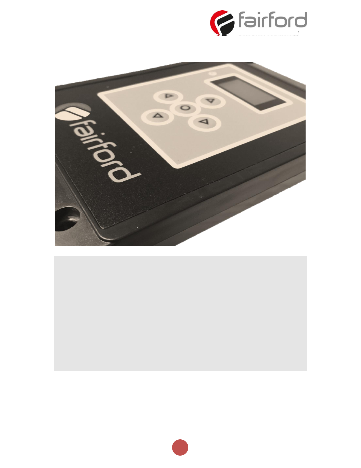
REMOTE KEYPAD USER GUIDE
MAN-AGY-005. Version 01
Page 2

2
MAN-AGY-005. Version 01 (01/11/2017)
Remote Keypad User Guide
Fairford Electronics Ltd
Bristow House
Gillard Way, Ivybridge
PL21 9GG
UK
www.fairford.com
[Full User Manual (MAN-AGY-001) available from www.fairford.com]
© 2017 by Fairford Electronics, all rights reserved
Copyright subsists in all Fairford Electronics deliverables including magnetic, optical and/or any
other soft copy of these deliverables. This document may not be reproduced, in full or in part,
without written permission. Enquiries about copyright of Fairford Electronics deliverables should
be made to Fairford Electronics Ltd. If, by permission of the copyright owner, any part of this
document is quoted, then a statement specifying the original document shall be added to the
quotation. Any such quotation shall be according to the original (text, figure or table) and may
not be shortened or modified.
Page 3
3
MAN-AGY-005. Version 01 (01/11/2017)
Network Connection
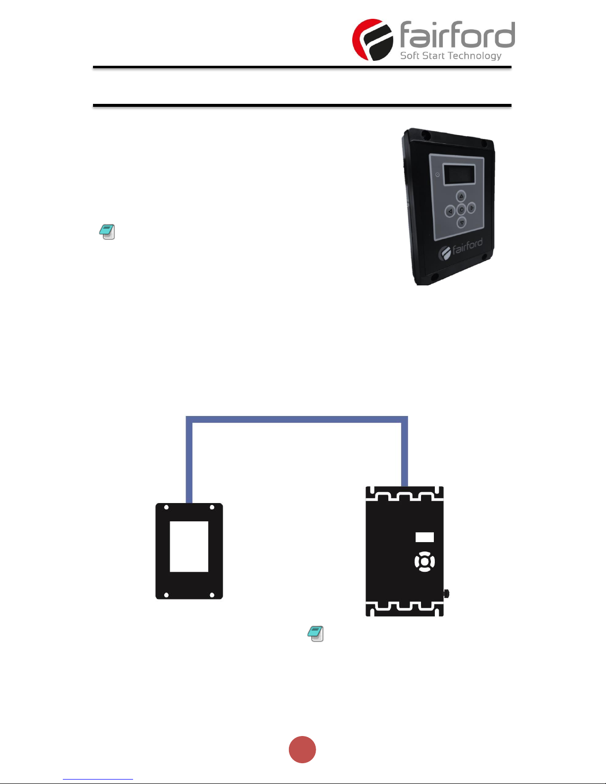
For a configuration where there is only one agilityTM unit (one-to-one), the remote and
main unit can be directly cabled. See Diagram below:
Connection and Operation
The remote keypad (AGY-010) can be used to control,
monitor and program up to 32 agilityTM soft starters.
The unit is powered from the host agility
TM
and
requires an Ethernet cable for communication
(Modbus RTU).
As the remote keypad acts as the Modbus master,
no additional master units must be placed within the
network. Failure to observe this may lead to erratic
behaviour, network failure and/or equipment
damage.
Keypad power must be enabled
on the agilityTM starter (see below)
Enabling Keypad Power: Scroll to DEVICE menu → KEYPAD menu → KEYPAD PWR = ON
Page 4
4
MAN-AGY-005. Version 01 (01/11/2017)
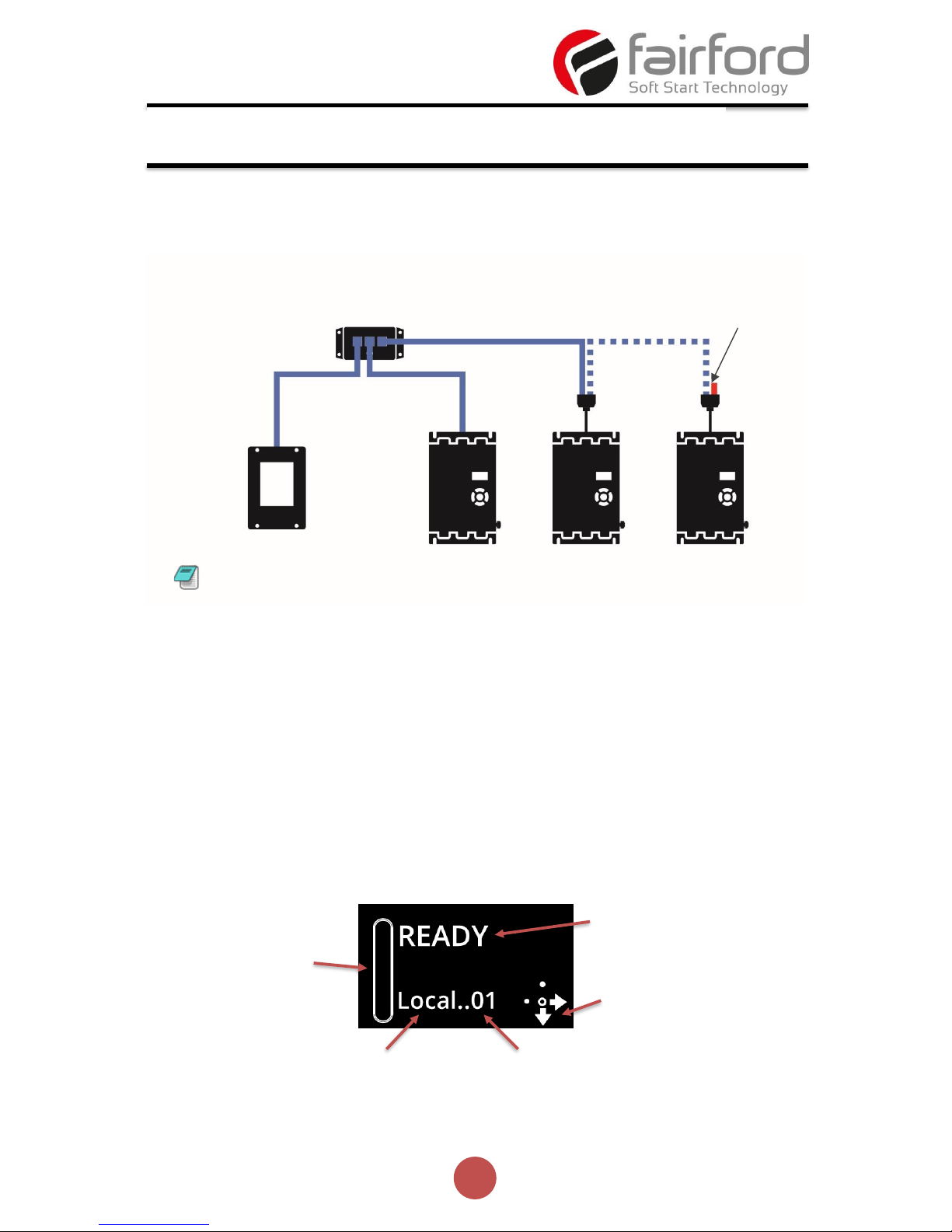
For multiple base units connected to the keypad, the use of SGY-011, CBL-036 and
CBL-035 (terminator) is highly recommended. See diagram below.
Operation
Once connected to the agilityTM host unit/s, menu structures and programming are the
same as detailed in the agilityTM manuals MAN-AGY-001 and MAN-AGY-002 (both may
be downloaded from www.fairford.co.uk).
However, specific steps must be taken to connect the Remote Keypad to one or more
agilityTM host units.
Initial Power-Up
If the host agilityTM unit/s and the remote keypad have the default Modbus transmission
parameters set, and the host unit is powered and has Keypad power set to ‘on’, the
keypad will automatically communicate with the host. The following status screen will
be seen:
Connection and Operation (continued)
SGY-011
Close Jumper S6
(supplies power to AGY-010)
CBL-036
CBL-035
(last unit only)
Enable keypad
power
on this unit
only
Status of connected host
Control method
(Local, Remote, Modbus)
Modbus address
of connected unit
Navigation Wizard
(displays ‘active’ keys)
Motor Overload level
The agilityTM units must have: a unique Modbus address on each unit and identical
Parity/Baud rate values on each unit
Address = 1
Address = 2
Address = 3
Page 5
5
MAN-AGY-005. Version 01 (01/11/2017)
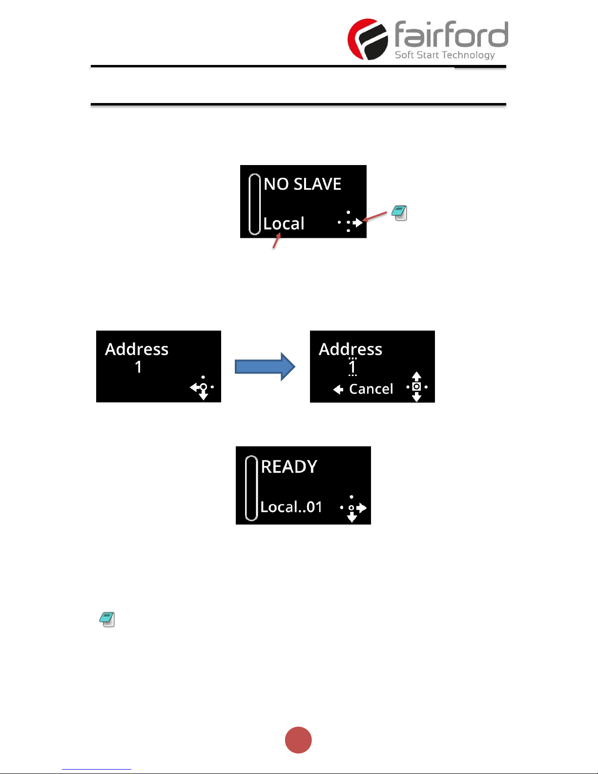
If any of the Modbus communication parameters are dissimilar on the host unit or
remote keypad, communication will not be established. The keypad will display the
following screen:
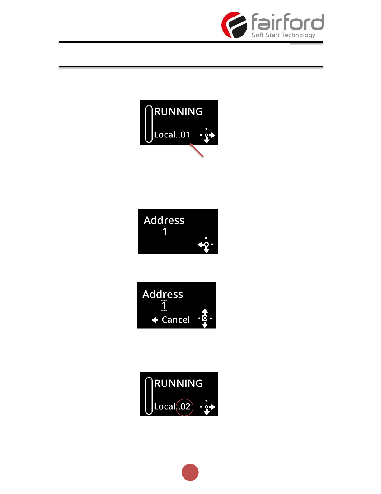
By pressing the Right key, the user will be taken directly to the Modbus address
selection menu:
If the selected Modbus address is valid, the status screen is displayed:
Selecting Units To Monitor/Configure
When the Remote Keypad is attached to multiple agilityTM units on the Modbus network,
the user can switch between each unit by using the following method.
(continued over)
Connection and Operation (continued)
Only Right key is active
May show: Local, Remote or Modbus
Press CENTRE key
Use UP / DOWN
keys to select
address.
Press centre to
confirm
To simplify this selection process it is recommended that the host agilityTM units are
configured with consecutive Modbus addresses
Page 6
6
MAN-AGY-005. Version 01 (01/11/2017)
Procedure:
1. Press the ‘Right’ key
2. Address selection screen will be shown
3. Press the ‘Centre’ key. Display will change mode
4. Use ‘Up’ or ‘Down’ keys to change address to the desired number (agilityTM address).
Press the ‘Centre’ key to confirm
5. Remote display will return to the Status screen and display the new address.
Connection and Operation (continued)
Modbus address
of connected unit
Page 7
7
MAN-AGY-005. Version 01 (01/11/2017)
Mounting
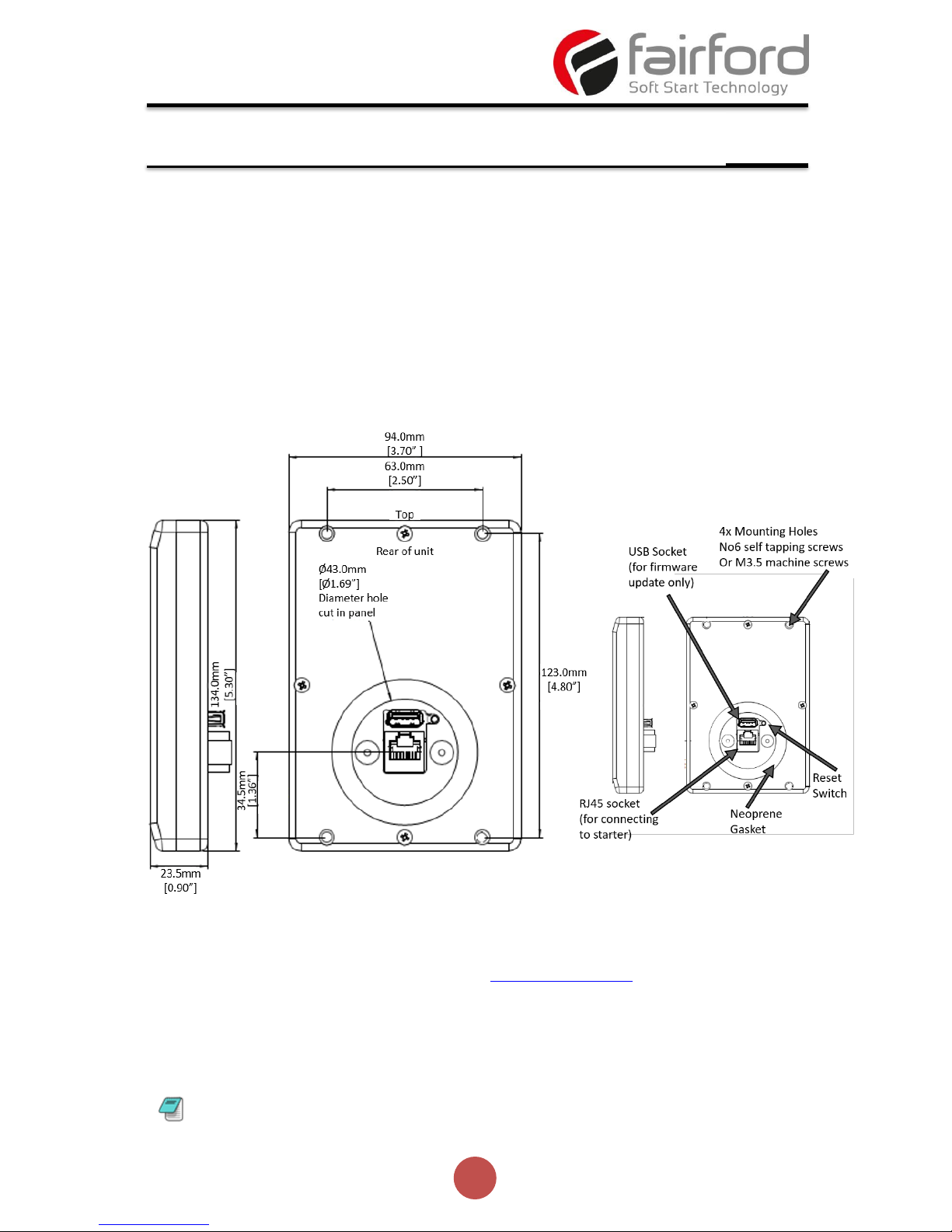
Fix the unit to a flat, vertical surface using the mounting holes in the keypad enclosure.
• The orientation of the unit has the ‘TOP’ uppermost.
• The location allows adequate front access.
• The screen can be viewed
Do not install other equipment that generates significant heat close to the keypad.
Firmware Update
1. Download the latest firmware version from www.fairford.co.uk and copy the files to a
USB flash drive.
2. Power down the Remote Keypad and insert the USB flash.
3. Power-up the remote Keypad, the update will start automatically
4. When the update is complete (status screen shown), recycle the Remote Keypad
power.
Installation
Note: The host units and Keypad must have the same firmware version.
Page 8

8
MAN-AGY-005. Version 01 (01/11/2017)
 Loading...