

Fairchild Semiconductor RHRP1560 Datasheet
CATHODE
(FLANGE)
CATHODE
ANODE
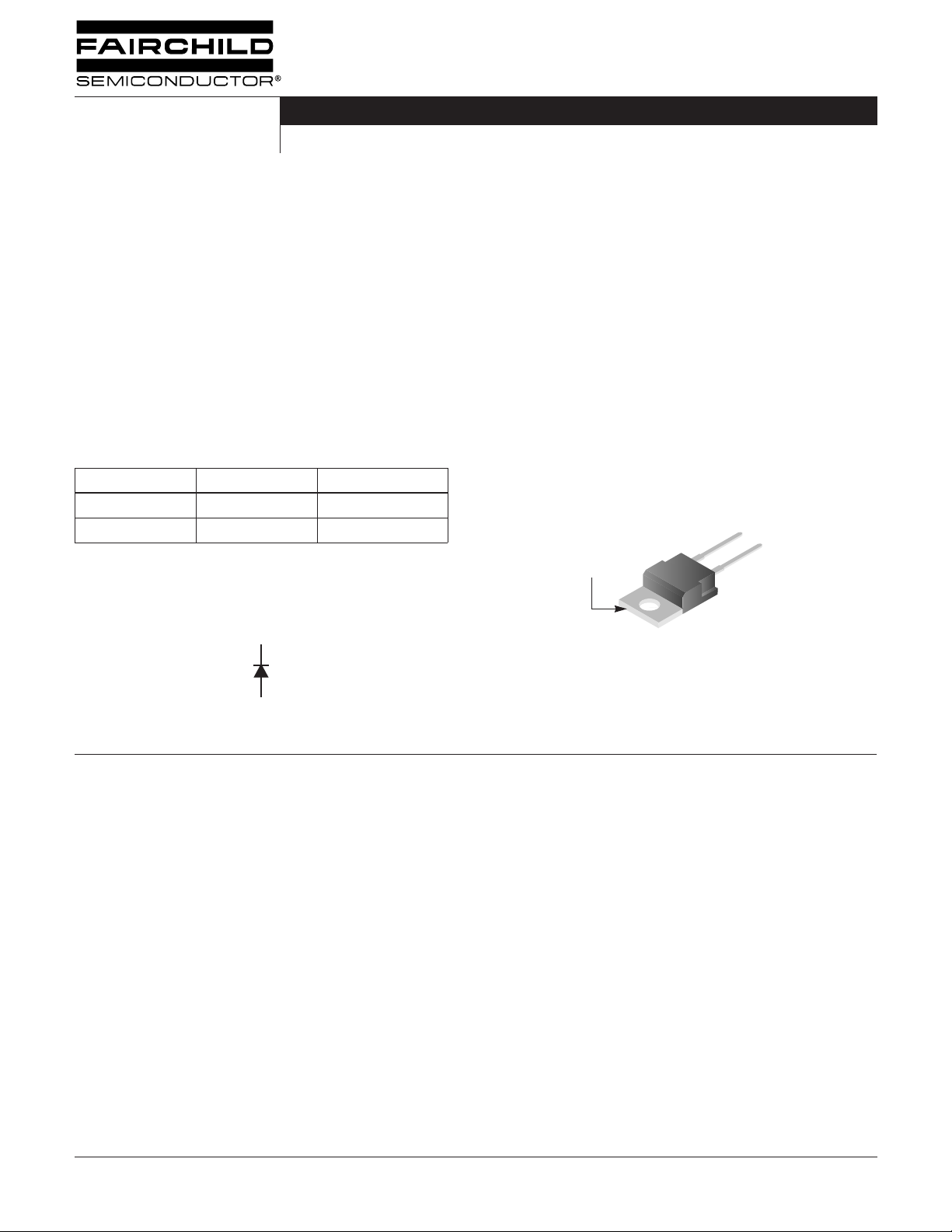
RHRP1540, RHRP1560
Data Sheet January 2002
15A, 400V - 600V Hyperfast Diodes
The RHRP1540 and RHRP1560 are hyperfast diodes with
soft recovery characteristics (t
< 35ns). They have half the
rr
recovery time of ultrafast diodes and are silicon nitride
passivated ion-implanted epitaxial planar construction.
These devices are intended for use as freewheeling/
clamping diodes and rectifiers in a variety of switching power
supplies and other power switching applications. Their low
stored charge and hyperfast soft recovery minimize ringing
and electrical noise in many power switching circuits
reducing power loss in the switching transistors.
Formerly developmental type TA49061.
Ordering Information
PART NUMBER PACKAGE BRAND
RHRP1540 TO-220AC RHRP1540
RHRP1560 TO-220AC RHRP1560
NOTE: When ordering, use the entire part number.
Symbol
K
Features
• Hyperfast with Soft Recovery. . . . . . . . . . . . . . . . . . <35ns
• Operating Temperature . . . . . . . . . . . . . . . . . . . . . . 175
o
• Reverse Voltage Up To. . . . . . . . . . . . . . . . . . . . . . . .600V
• Avalanche Energy Rated
• Planar Construction
Applications
• Switching Power Supplies
• Power Switching Circuits
• General Purpose
Packaging
JEDEC TO-220AC
C
A
Absolute Maximum Ratings
Peak Repetitive Reverse Voltage . . . . . . . . . . . . . . . . . . . . . . . . . . . . . . . . . . . . . . . . . V
Working Peak Reverse Voltage . . . . . . . . . . . . . . . . . . . . . . . . . . . . . . . . . . . . . . . . . .V
DC Blocking Voltage . . . . . . . . . . . . . . . . . . . . . . . . . . . . . . . . . . . . . . . . . . . . . . . . . . . . .V
Average Rectified Forward Current . . . . . . . . . . . . . . . . . . . . . . . . . . . . . . . . . . . . . . . I
(T
Repetitive Peak Surge Current . . . . . . . . . . . . . . . . . . . . . . . . . . . . . . . . . . . . . . . . . . . I
(Square Wave, 20kHz)
Nonrepetitive Peak Surge Current. . . . . . . . . . . . . . . . . . . . . . . . . . . . . . . . . . . . . . . . . I
(Halfwave, 1 Phase, 60Hz)
Maximum Power Dissipation . . . . . . . . . . . . . . . . . . . . . . . . . . . . . . . . . . . . . . . . . . . . . . .P
Avalanche Energy (See Figures 10 and 11) . . . . . . . . . . . . . . . . . . . . . . . . . . . . . . . . . E
Operating and Storage Temperature . . . . . . . . . . . . . . . . . . . . . . . . . . . . . . . . . . . .T
©2002 Fairchild Semiconductor Corporation RHRP1540, RHRP1560 Rev. B
= 140
C
o
C)
o
T
= 25
C, Unless Otherwise Specified
C
RHRP1540 RHRP1560 UNITS
400 600 V
400 600 V
400 600 V
15 15 A
30 30 A
200 200 A
100 100 W
20 20 mJ
-65 to 175 -65 to 175
o
STG
RRM
RWM
F(AV)
FRM
FSM
AVL
, T
R
D
J
C
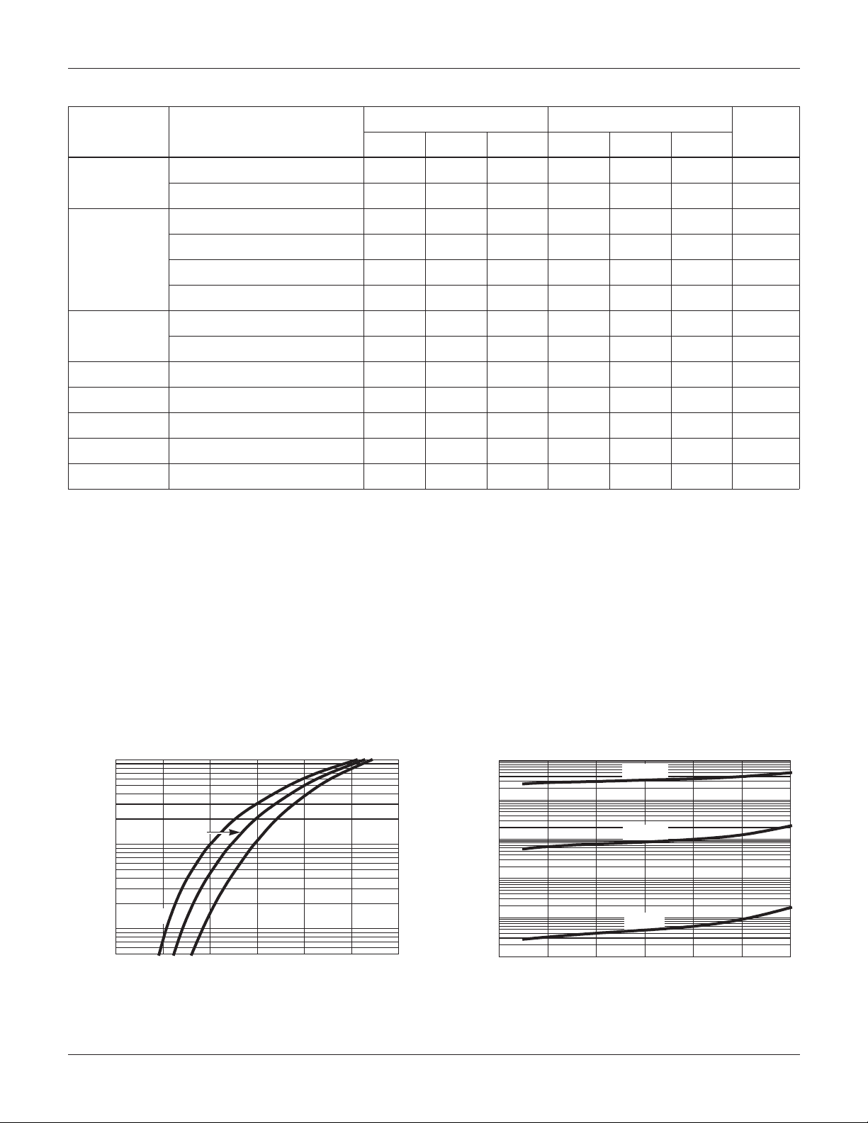
VR, REVERSE VOLTAGE (V)
0 200 400 600300 500
1000
0.01
0.1
1
10
100
100
25oC
100oC
175oC
I
R
, REVERSE CURRENT (µA)
µ
µ
θ
θ
RHRP1540, RHRP1560
Electrical Specifications
o
T
= 25
C, Unless Otherwise Specified
C
SYMBOL TEST CONDITION
V
F
I
R
t
rr
t
a
t
b
Q
RR
C
J
R
JC
I
= 15A - - 2.1 - - 2.1 V
F
I
= 15A, T
F
V
= 400V - - 100 - - -
R
V
= 600V -----100 µ A
R
V
= 400V, T
R
V
= 600V, T
R
I
= 1A, dI
F
I
F
I
F
I
F
I
F
V
R
F
= 15A, dI
= 15A, dI
= 15A, dI
= 15A, dI
= 10V, I
o
= 150
C
C - - 1.7 - - 1.7 V
o
= 150
C
C
C - - 500 - - -
o
= 150
C -----500 µ A
/dt = 100A/ µ s - -35- -35ns
/dt = 100A/ µ s - -40- -40ns
F
/dt = 100A/ µ s - 20 - - 20 - ns
F
/dt = 100A/ µ s - 15 - - 15 - ns
F
/dt = 100A/ µ s - 40 - - 40 - nC
F
= 0A -60- -60- pF
F
DEFINITIONS
V
= Instantaneous forward voltage (pw = 300 µ s, D = 2%).
F
I
= Instantaneous reverse current .
R
t
= Reverse recovery time (See Figure 9), summation of t
rr
t
= Time to reach peak reverse current (See Figure 9).
a
t
= Time from peak I
b
Q
= Reverse Recovery Change.
RR
C
= Junction Capacitance.
J
R
= Thermal resistance junction to case.
JC
to projected zero crossing of I
RM
pw = Pulse Width.
D = Duty Cycle.
RHRP1540 RHRP1560
- - 1.5 - - 1.5
+ t
.
a
b
based on a straight line from peak I
RM
through 25% of I
RM
(See Figure 9).
RM
UNITSMIN TYP MAX MIN TYP MAX
o
A
A
C/W
Typical Performance Curves
100
175oC
100oC
25oC
0.5
1
VF, FORWARD VOLTAGE (V)
, FORWARD VOLTAGE (V)
V
F
10
, FORWARD CURRENT (A)
F
I
1
0.5
0
FIGURE 1. FORWARD CURRENT vs FORWARD VOLTAGE FIGURE 2. REVERSE CURRENT vs REVERSE VOLTAGE
©2002 Fairchild Semiconductor Corporation RHRP1540, RHRP1560 Rev. B
1.5
2 2.5
3
 Loading...