

Fairchild Semiconductor RGP10K, RGP10A, RGP10G, RGP10J, RGP10B Datasheet
...
Discrete POWER & Signal
Technologies
RGP10A - RGP10M
Features
• 1.0 ampere operation at T
with no thermal runaway.
• High temperature metallurgically
bonded construction.
• Glass passivated cavity-free junction.
• Typical I
less than 1µA.
R
• Fast switching for high efficiency.
1.0 Ampere Glass Passivated Fast Recovery Rectifiers
= 55°C
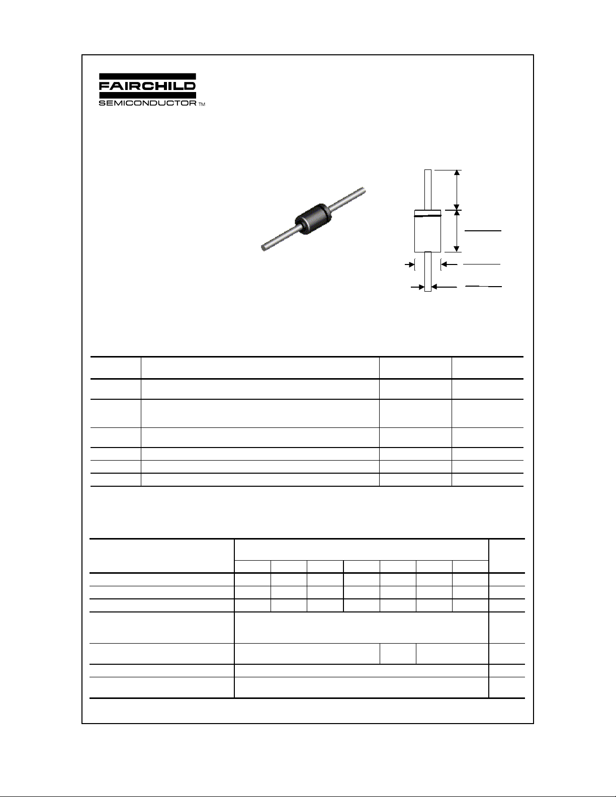
A
COLOR BAND DENOTES CATHODE
DO-41
1.0 min (25.4)
Dimens i o ns in
inches (mm)
0.205 (5.21)
0.160 (4.06)
0.107 (2.72)
0.080 (2.03)
0.034 (0.86)
0.028 (0.71)
RGP10A-RGP10M
Absolute Maximum Ratings* T
= 25°C unless otherwise noted
A
Symbol Parameter Value Units
I
O
i
f(surge)
P
D
R
θ
JA
T
stg
T
J
Average Rectified Current
.375 " lead length @ T
= 55°C
L
Peak Forward Surge Current
8.3 ms single half-si ne-wave
Superimposed on rated load (JEDEC method)
Total Device Dissipation
Derate above 25°C
Thermal Resistance, J unct i on to Ambient 50
Storage Temperature Range -65 to +175
Operating Junction Temperature -65 to +175
1.0 A
30 A
2.5
17
mW/°C
°C/W
W
°C
°C
*These ratings are limiting values above which the serviceability of any semiconductor device may be impaired.
Electrical Characteristics T
= 25°C unless otherwise noted
A
Parameter Device Units
10A 10B 10D 10G 10J 10K 10M
Peak Repetitive Reverse Voltage 50 100 200 400 600 800 1000 V
Maximum RMS Voltage 35 70 140 280 420 560 700 V
DC Reverse Voltage (Rated VR)
Maximum Reverse Current
@ rated V
R
TA = 25°C
= 150°C
T
A
Maximum Reverse Recovery Time
= 0.5 A, IR = 1.0 A, I
I
F
= 0.25 A
rr
Maximum Forward Voltage @ 1.0 A 1.3 V
Typical Junction Capacitance
V
= 4.0 V, f = 1.0 MHz
R
50 100 200 400 600 800 1000 V
5.0
200
150 250 500 nS
15 pF
A
µ
A
µ
1999 Fairchild Semiconductor Corporation
RPG10A - RPG10M, Rev. A
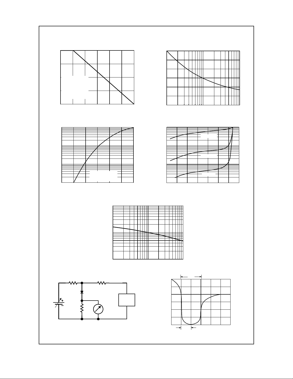
T ypical Characteristics
RGP10A-RGP10M
Forward Current De ratin g Curve
1
0.75
SINGLE PHASE
0.5
HALF WAV E
60HZ
RESISTIVE OR
INDUCTIVE LOAD
0.25
.375" (9.0mm ) LEAD
FORWAR D CURRE NT (A )
LENGTH S
0
25 50 75 100 125 150 175
LEAD TEMPERATURE ( C)
º
Forward Characteristics
10
1
0.1
T = 25 C
FORWARD CU RRENT (A)
0.01
0.4 0.6 0.8 1 1.2 1.4 1.6
FORWAR D VOLTA GE (V)
º
A
Pulse Widt h = 300µs
2% Duty Cycle
Non-Repetitive Surge Current
30
25
20
15
10
5
0
PEAK FORWARD SURGE CURRENT (A)
1 2 5 10 20 50 100
NUMBER O F CYCL ES AT 60Hz
Reverse Characteristics
10
T = 125 C
º
µ
1
0.1
REVERSE CURRENT ( A)
0.01
0 20406080100120140
PERCENT OF RATED PEAK REVERSE VOLTAGE (%)
A
T = 75 C
º
A
º
T = 25 C
A
Junctio n Cap a cita nc e
100
50
20
10
5
CAPACITANCE (pF)
2
1
50
Ω
NONINDUCTIVE
50V
(approx)
Ω
50
NONINDUCTIVE
Ω
50
NONINDUCTIVE
DUT
1 2 5 10 20 50 100
OSCILLOSCOPE
(Note 1)
REVERSE VOLTAGE (V)
(-)
Pulse
Generator
(Note 2)
(+)
+0.5A
trr
0
-0.25A
-1.0A
1.0cm SET TIME BASE FOR
Reverse Recovery Time Characterstic and Test Circuit Diagram
5/ 10 ns/ cm
RPG10A - RPG10M, Rev. A
 Loading...