

Fairchild Semiconductor QTLP321C-E, QTLP321C-R, QTLP321C-Y Datasheet

4 - PIN POWER LED
1 of 3 1/4/00 300018A
Parameter Symbol Rating Unit
Operating Temperature T
OPR
-40 to +100 °C
Storage Temperature T
STG
-40 to +100 °C
Lead Soldering Time T
SOL
260 for 5 sec °C
Continuous Forward Current I
F
70 mA
Peak Forward Current
I
F
200 mA
(f = 100 Hz, Duty Factor = 1/10)
Reverse Voltage V
R
5V
Power Dissipation P
D
160 mW
ABSOLUTE MAXIMUM RATINGS
(TA= 25°C unless otherwise specified)
0.320 (8.12)
0.280 (7.12)
0.320 (8.12)
0.280 (7.12)
0.118 (3.00)
0.079 (2.00)
R0.035 (0.90)
R0.020 (0.50)
0.181 (4.60)
0.166 (4.20)
0.303 (7.70)
0.287 (7.50)
0.020 (0.50)
0.033 (0.85)
0.026 (0.65)
5°
0.024 (0.60)
0.008 (0.20)
TYP.
0.212 (5.38)
0.188 (4.78)
0.075 (1.90)
0.069 (1.75)
0.053 (1.35)
C - CATHODE
A - ANODE
CC
AA
C. 0.050 (1.25)
Ø 0.126 (3.20 )
Ø 0.110 (2.80)
PACKAGE DIMENSIONS
RED QTLP321C-R
ORANGE QTLP321C-E
YELLOW QTLP321C-Y
NOTES:
1. Dimensions for all drawings are in inches (mm).
2. Lead spacing is measured where the leads emerge from
the package.
3. Protruded resin under the flange is 0.059" (1.5 mm) max.
4. All tolerances are ±0.10” (0.25 mm) unless otherwise
specified.
APPLICATIONS
• Exterior automotive lighting
• Area displays
• Backlighting
• Message panels
FEATURES
• AllnGaP (Aluminum Indium Gallium Phosphide) technology
• High current application
• Reduced thermal resistance
• Tube packaging
DESCRIPTION
This low profile, 4-pin LED provides a more uniform and
evenly distributed illumination than existing LED designs. Its
unique optical package enables designers to utilize fewer LEDs
while achieving superior lighting performance.
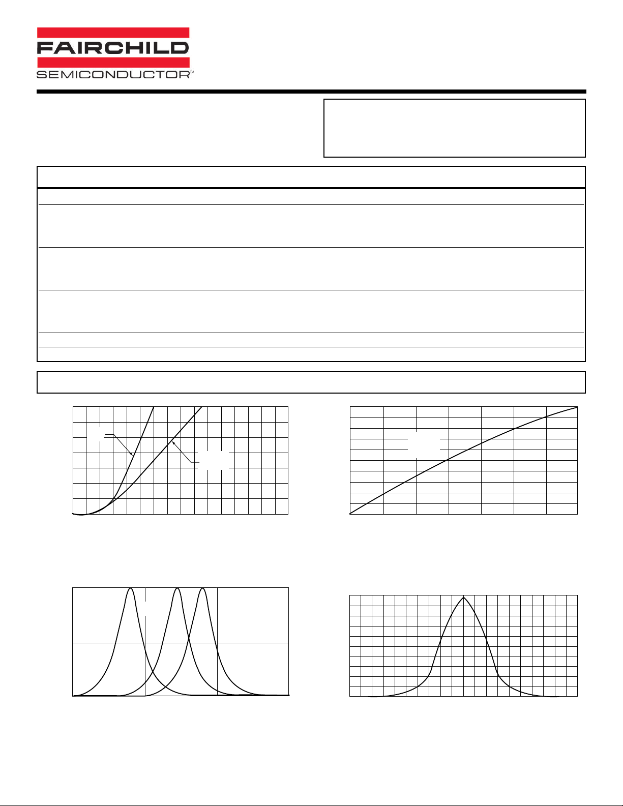
TYPICAL PERFORMANCE CURVES
4 - PIN POWER LED
2 of 3 1/4/00 300018A
RED QTLP321C-R
ORANGE QTLP321C-E
YELLOW QTLP321C-Y
Part Number QTLP321C-R QTLP321C-E QTLP321C-Y Condition
Luminous Flux (mlm) IF= 70 mA
Minimum 500 500 500
Typical 1300 1300 1300
Forward Voltage VF(V) IF= 20 / 70 mA
Maximum 2.4 / 2.8 2.4 / 2.8 2.4 / 2.8
Typical 2.0 / 2.2 2.0 / 2.2 2.0 / 2.2
Wavelength (nm) IF= 70 mA
Peak 640 620 590
Dominant 630 615 589
Spectral Line Half Width (nm) 20 18 15 IF= 70 mA
Viewing Angle (°)505050I
F
= 70 mA
ELECTRICAL / OPTICAL CHARACTERISTICS
(TA
=25°C)
70
60
50
40
30
20
10
FORWARD CURRENT (mA)
1.0
0.5
RELATIVE INTENSITY
RED
YELLOW
ORANGE
0
1.5 1.7 1.9 2.1 2.3 2.5 2.7 2.9 3.1
FORWARD V OLTAGE (V)
Fig. 1 Forward Current vs. Forward Voltage
ORANGE
YELLOW
RED
1.0
0.9
0.8
0.7
0.6
0.5
0.4
0.3
0.2
0.1
RELATIVE LUMINOUS FLUX
0
0 10203040506070
RED
YELLOW
ORANGE
FORWARD CURRENT(mA)
Fig. 2 Relative Luminous Flux vs. Forward Current
1
0.5
0
550 600 650 700
WAVELENGTH - nm
Fig. 3 Relative Intensity vs Peak Wavelength
REL. LUMINOUS INTENSITY
0
90 80 70 60 50 40 30 20 10 0 10 20 30 40 50 60 70 80 90
ANGLE FROM OPTICAL CENTERLINE (DEGREES)
Fig. 4 Rel. Luminous Intensity
vs. Angular Displacement
 Loading...