

0.510-INCH (13MM)
SEVEN SEGMENT DISPLAYS
YELLOW MAN5350/5360 RED MAN5750/5760
GREEN MAN5450/5460 HER MAN5950/5960
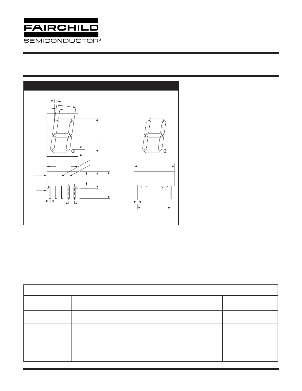
PACKAGE DIMENSIONS
10°
0.049
(1.25mm)
0.482
(12.25mm)
±0.004
0.020
(0.5mm)
Part
No.
XYY Z
Part
Identification
Pin #1
NOTE: Dimensions in inches (mm)
Tolerances ±0.010" unless otherwise specified
±0.006
0.291
(7.4mm)
(1.25mm)
0.252
(6.4mm)
0.100
(2.54mm)
0.512 (13mm)
0.049
Date Code
Light Intensity Category
±0.012
0.276
(7.0mm)
0.417
(10.6mm)
±0.012
F
E
0.012
(0.3mm)
G
D
0.689
(17.5mm)
±0.002
0.600
(15.24mm)
A
C
+0.012
-0.004
±0.006
DESCRIPTION
This display series is a family of large digits
0.510 inches in height. All models have right
hand decimal points and are availble in common
anode or common cathode configurations. All
units are constructed with untinted segments on
grey face to enhance ON/OFF contrast. Stan-
B
dard units are available in red, orange-red,
green and yellow.
FEATURES
DP
• Large, easy to read, digits
• Common anode or common cathode models
•Fast switching — excellent for multiplexing
•Low power consumption
• Bold solid segments that are highly legible
• Solid state reliability — long operation life
• Rugged plastic construction
• Directly compatible with integrated circuits
• High brightness with high contrast
• Categorized for Luminous Intensity
(See Note 5)
• Wide angle viewing...150°
•Low forward voltage
• Untinted segments on grey face
APPLICATIONS
For industrial and consumer applications such as:
• Digital readout displays
• Instrument panels
•Point of sale equipment
• Digital clocks
• TV and radios
MODEL NUMBERS
Part Number Color Description
MAN5350
MAN5360
MAN5450
MAN5460
MAN5750
MAN5760
MAN5950
MAN5960
© 2003 Fairchild Semiconductor Corporation
Yellow
Yellow
Green
Green
Red
Red
HER
HER
Common Anode
Common Cathode
Common Anode
Common Cathode
Common Anode
Common Cathode
Common Anode
Common Cathode
Page 1 of 10
Pin Out Specification
(See Page 5)
A
B
A
B
A
B
A
B
7/21/03
0.510-INCH (13MM)
SEVEN SEGMENT DISPLAYS
YELLOW MAN5350/5360 RED MAN5750/5760
GREEN MAN5450/5460 HER MAN5950/5960
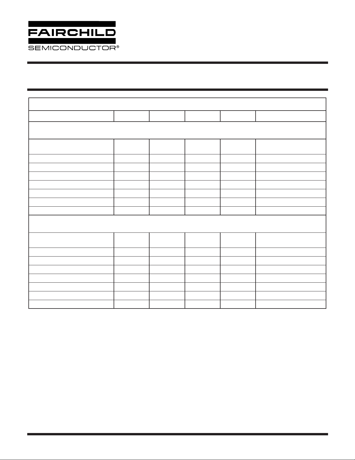
ELECTRO-OPTICAL CHARACTERISTICS
(T
= 25°C Unless Otherwise Specified)
A
Parameter Min. Typ. Max. Units Test Condition
Yellow
MAN5350/MAN5360
Luminous Intensity, digit average
(See Note 1)
Peak emission wavelength 585 nm I
Dominant wavelength 582 593 nm I
820 1200
480
µcd
µcd
I
= 10 mA
F
I
= 5 mA
F
= 10 mA
F
= 10 mA
F
Spectral line half width 40 nm
Forward voltage 2.4 3.0 V I
Dynamic resistance 26 I
Capacitance 35 pF V
Reverse current 10 µA V
= 20 mA
F
= 20 mA
F
= 0, f = 1MHz
R
= 6.0 V
R
Green
MAN5450/MAN5460
Luminous Intensity, digit average
(See Note 1)
Peak emission wavelength 562 nm I
Dominant wavelength 564 574 nm I
820 3000
1000
µcd
µcd
I
= 10 mA
F
I
= 5 mA
F
= 10 mA
F
= 10 mA
F
Spectral line half width 30 nm
Forward voltage 2.4 3.0 V I
Dynamic resistance 12 I
Capacitance 40 pF V
Reverse current 10 µA V
= 20 mA
F
= 20 mA
F
= 0, f = 1MHz
R
= 6.0 V
R
© 2003 Fairchild Semiconductor Corporation
Page 2 of 10
7/21/03

0.510-INCH (13MM)
SEVEN SEGMENT DISPLAYS
YELLOW MAN5350/5360 RED MAN5750/5760
GREEN MAN5450/5460 HER MAN5950/5960
ELECTRO-OPTICAL CHARACTERISTICS
(T
= 25°C Unless Otherwise Specified)
A
Parameter Min. Typ. Max. Units Test Condition
Red
MAN5750/MAN5760
Luminous Intensity, digit average
(See Note 1)
Peak emission wavelength 655 nm I
Dominant wavelength 645 nm I
280 500
250
µcd
µcd
I
= 10 mA
F
I
= 5 mA
F
= 10 mA
F
= 10 mA
F
Spectral line half width 20 nm
Forward voltage 1.6 2.0 V I
Dynamic resistance 2 I
Capacitance 35 pF V
Reverse current 10 µA V
= 20 mA
F
= 20 mA
F
= 0, f = 1MHz
R
= 6.0 V
R
HER
MAN5950/MAN5960
Luminous Intensity, digit average
(See Note 1)
Peak emission wavelength 635 nm I
Dominant wavelength 615 630 nm I
820 2500
700
µcd
µcd
I
= 10 mA
F
I
= 5 mA
F
= 10 mA
F
= 10 mA
F
Spectral line half width 40 nm
Forward voltage 2.0 3.0 V I
Dynamic resistance 26 I
Capacitance 35 pF V
Reverse current 10 µA V
= 20 mA
F
= 20 mA
F
= 0, f = 1MHz
R
= 6.0 V
R
© 2003 Fairchild Semiconductor Corporation
Page 3 of 10
7/21/03

0.510-INCH (13MM)
SEVEN SEGMENT DISPLAYS
YELLOW MAN5350/5360 RED MAN5750/5760
GREEN MAN5450/5460 HER MAN5950/5960
ABSOLUTE MAXIMUM RATINGS
Rating
Power dissipation at 25°C ambient 600 mW 570 mW 480 mW 600 mW
Derate linearly from 50°C -10.3 mW/°C -12 mW/°C -6.9 mW/°C -8.6 mW/°C
Storage and operating temperature -40°C to +85°C -40°C to +85°C -40°C to +85°C -40°C to +85°C
Continuous forward current
Total
Per segment
Decimal point
Reverse voltage
Per segment
Decimal point
Soldering time at 260°C (See Notes 3 and 4) 5 sec. 5 sec. 5 sec. 5 sec.
Notes:
1. The digit average Luminous Intensity is obtained by summing the Luminous Intensity of each segment and dividing by the total
number of segments. Intensity will not vary more than ±33.3% between all segments within a digit.
2. The relative Luminous Intensity in this curve is normalized to the brightness at 25°C to indicate the relative efficiency over the
operating temperature range.
3. Leads of the device immersed to 1/16 inch from the body. Maximum device surface temperature is 140°C.
4. For flux removal, Freon TF, Freon TE, Isoproponal or water may be used to up their boiling points.
5. All displays are categorized for Luminous Intensity. The intensity category is marked on each part as a suffix letter to the part
number.
MAN5350
MAN5360
200 mA
25 mA
25 mA
6.0 V
6.0 V
MAN5450
MAN5460
240 mA
30 mA
30 mA
6.0 V
6.0 V
MAN5750
MAN5760
240 mA
30 mA
30 mA
6.0 V
6.0 V
MAN5950
MAN5960
240 mA
30 mA
30 mA
6.0 V
6.0 V
RECOMMENDED OPTICAL FILTERS
For optimum ON and OFF contrast, one of the following filters or equivalents should be used over the display:
Device Type Filter Device Type Filter
Panelgraphic Yellow 25 or Amber 23
MAN5350
MAN5360
MAN5750
MAN5760
© 2003 Fairchild Semiconductor Corporation
Homalite 100-1720 or 100-1726
Panelgraphic Grey 10
Homalite 100-1266 Grey
Panelgraphic Red 60
Homalite 100-1605
MAN5450
MAN5460
MAN5950
MAN5960
Page 4 of 10
Panelgraphic Green 48
Homalite 100-1440 Green
Panelgraphic Grey 10
Homalite 100-1266 Grey
Panelgraphic Scarlet 65
Homalite 100-1670
7/21/03

0.510-INCH (13MM)
SEVEN SEGMENT DISPLAYS
YELLOW MAN5350/5360 RED MAN5750/5760
GREEN MAN5450/5460 HER MAN5950/5960
ELECTRICAL CONNECTIONS
Pin No.
1 Cathode E Anode E
2 Cathode D Anode D
3 Com. Anode Com. Cathode
4 Cathode C Anode C
5 Cathode D.P. Anode D.P.
6 Cathode B Anode B
7 Cathode A Anode A
8 Com. Anode Com. Cathode
9 Cathode F Anode F
10 Cathode G Anode G
A
MAN5X50
INTERNAL CONNECTIONS
8
3
8
3
B
MAN5X60
E1D2C4B6A7F9G10DP
© 2003 Fairchild Semiconductor Corporation
5
MAN5X50 MAN5X60
Page 5 of 10
E1D2C4B6A7F9G10DP
5
7/21/03

0.510-INCH (13MM)
SEVEN SEGMENT DISPLAYS
YELLOW MAN5350/5360 RED MAN5750/5760
GREEN MAN5450/5460 HER MAN5950/5960
TYPICAL CHARACTERISTIC CURVES — MAN5350/MAN5360
4.0
NORMALIZED at IF = 10 mA
3.0
2.0
1.0
Relative Luminous Intensity
0
051015 20 25 30
DC Forward Current – I
Fig. 1A. Relative Luminous Intensity
vs. DC Forward Current
120
110
100
90
80
Relative Brightness - %
70
-50 -25 0 25 50 70
Ambient Temperature – °C
(mA)
F
100
90
80
70
60
50
- mA
F
40
I
30
20
10
0
Fig. 1B. Forward Current vs. Forward Voltage
1000
800
500
200
- mA
F
100
80
50
Peak I
20
10
123581020305080100
1.0
2.0 3.00 4.0
VF (Volts)
FREQUENCY = 200pps
Duty Cycle – %
Fig. 1C. Relative Luminous Intensity vs. Temperature
(See Note 2)
© 2003 Fairchild Semiconductor Corporation
Fig. 1D. Max Peak Current vs. Duty Cycle
2.0
1.5
Relative Intensity
1
10 20 40 DC
Duty Cycle – %
IF Per Seg 10 mA Average
Fig. 1E. Relative Luminous Intensity vs. Duty Cycle
Page 6 of 10
7/21/03

0.510-INCH (13MM)
SEVEN SEGMENT DISPLAYS
YELLOW MAN5350/5360 RED MAN5750/5760
GREEN MAN5450/5460 HER MAN5950/5960
TYPICAL CHARACTERISTIC CURVES — MAN5450/MAN5460
4.0
NORMALIZED at IF = 10 mA
3.0
2.0
1.0
Relative Luminous Intensity
0
051015 20 25 30
DC Forward Current – I
Fig. 2A. Relative Luminous Intensity
vs. DC Forward Current
130
120
110
100
90
80
Relative Intensity – %
70
-55 -25 0 25 50 75 100
Ambient Temperature – °C
NORMALIZED at 25°C
(mA)
F
100
90
80
(mA)
F
70
60
50
40
30
20
10
Forward Current - I
0
Fig. 2B. Forward Current vs.Forward Voltage
4.0
3.0
2.0
at 10 mA DC)
L
1.0
Relative Efficiency
at drive/I
L
(I
0.0
(Dotted Line
Indicates Pulsed
Operation See Figs 2D, 2E)
2.0
Forward Voltage – VF (Volts)
I
= 20 mA
F (AVG)
10 mA
5 mA
2.5mA
2.0 5.0 10 20 50 DC
Duty Cycle – %
3.01.0 4.0
Fig. 2C. Relative Luminous Intensity vs. Temperature
(See Note 2)
© 2003 Fairchild Semiconductor Corporation
Fig. 2D. Relative Efficiency vs. Duty Cycle
1000
800
600
400
200
100
Maximum Peak Current - mA
10 KHz
80
60
40
20
10
10 100 1000 10.000
Fig. 2E. Maximum Peak Current vs. Pulse Duration
30 KHz
Pulse Duration – µS
1.0 KHz
300 KHz
100 KHz
Page 7 of 10
7/21/03

0.510-INCH (13MM)
SEVEN SEGMENT DISPLAYS
YELLOW MAN5350/5360 RED MAN5750/5760
GREEN MAN5450/5460 HER MAN5950/5960
TYPICAL CHARACTERISTIC CURVES — MAN5750/MAN5760
4.0
NORMALIZED at IF = 10 mA
3.0
2.0
1.0
Relative Luminous Intensity
0
051015 20 25 30
DC Forward Current – IF (mA)
Fig. 3A. Relative Luminous Intensity
vs. DC Forward Current
170
160
150
140
130
120
110
100
90
80
70
Relative Brightness - %
60
50
-50 -25 0 25 50 70
Ambient Temperature – °C
100
90
80
70
60
50
- mA
F
40
I
30
20
10
0
Fig. 3B. Forward Current vs. Forward Voltage
1000
800
500
200
- mA
F
100
80
50
Peak I
20
10
123581020305080100
5
VF (Volts)
Duty Cycle – %
10 15020
FREQUENCY = 200pps
Fig. 3C. Relative Luminous Intensity vs. Temperature
(See Note 2)
© 2003 Fairchild Semiconductor Corporation
Fig. 3D. Max Peak Current vs. Duty Cycle
2
Relative Intensity
1
10 20 40 DC
Percent Duty Cycle
Fig. 3E. Relative Luminous Intensity vs. Duty Cycle
Page 8 of 10
7/21/03

0.510-INCH (13MM)
SEVEN SEGMENT DISPLAYS
YELLOW MAN5350/5360 RED MAN5750/5760
GREEN MAN5450/5460 HER MAN5950/5960
TYPICAL CHARACTERISTIC CURVES — MAN5950/MAN5960
4.0
NORMALIZED at IF = 10 mA
3.0
2.0
1.0
Relative Luminous Intensity
0
051015 20 25 30
DC Forward Current – I
Fig. 4A. Relative Luminous Intensity vs. Forward Current
170
160
150
140
130
120
110
100
90
80
70
Relative Intensity – %
60
50
-50 -25 0 25 50 70
Ambient Temperature – °C
(mA)
F
100
90
80
70
60
50
) - mA
F
40
(I
30
20
10
0
4
8 1.20 1.6 2.0 2.4 2.8 3.2 3.6 4.0
Forward Voltage – VF (Volts)
Fig. 4B. Forward Current vs. Forward Voltage
1000
800
500
200
– mA
100
F
80
50
Peak I
20
10
FREQUENCY = 200pps
135102050100
Duty Cycle – %
Fig. 3C. Relative Luminous Intensity vs. Temperature
(See Note 2)
© 2003 Fairchild Semiconductor Corporation
Fig. 4D. Maximum Peak Current vs. Duty Cycle
2
1.5
Relative Intensity
1
10 20 40 DC
Duty Cycle – %
Per Seg 10 mA Average
I
F
Fig. 4E. Relative Luminous Intensity vs. Duty Cycle
Page 9 of 10
7/21/03

0.510-INCH (13MM)
SEVEN SEGMENT DISPLAYS
YELLOW MAN5350/5360 RED MAN5750/5760
GREEN MAN5450/5460 HER MAN5950/5960
DISCLAIMER
FAIRCHILD SEMICONDUCTOR RESERVES THE RIGHT TO MAKE CHANGES WITHOUT FURTHER NOTICE TO
ANY PRODUCTS HEREIN TO IMPROVE RELIABILITY, FUNCTION OR DESIGN. FAIRCHILD DOES NOT ASSUME
ANY LIABILITY ARISING OUT OF THE APPLICATION OR USE OF ANY PRODUCT OR CIRCUIT DESCRIBED HEREIN;
NEITHER DOES IT CONVEY ANY LICENSE UNDER ITS PATENT RIGHTS, NOR THE RIGHTS OF OTHERS.
LIFE SUPPORT POLICY
FAIRCHILD’S PRODUCTS ARE NOT AUTHORIZED FOR USE AS CRITICAL COMPONENTS IN LIFE SUPPORT DEVICES
OR SYSTEMS WITHOUT THE EXPRESS WRITTEN APPROVAL OF THE PRESIDENT OF FAIRCHILD SEMICONDUCTOR
CORPORATION. As used herein:
1. Life support devices or systems are devices or systems
which, (a) are intended for surgical implant into the body, or
(b) support or sustain life, and (c) whose failure to perform
when properly used in accordance with instructions for use
provided in the labeling, can be reasonably expected to
result in a significant injury of the user.
2. A critical component in any component of a life support
device or system whose failure to perform can be
reasonably expected to cause the failure of the life support
device or system, or to affect its safety or effectiveness.
© 2003 Fairchild Semiconductor Corporation
Page 10 of 10
7/21/03
 Loading...