

Fairchild Semiconductor 74LVQ157SJX, 74LVQ157SJ, 74LVQ157SCX, 74LVQ157SC Datasheet
74LVQ157
Low Voltage Quad 2-Input Multiplexer
General Description
The LVQ157 is a high-speed quad 2-input multiplexer. Four
bits ofdata from two sources can be selected using the common Select and Enable inputs. The four outputs present the
selected data in the true (noninverted) form. The LVQ157
can also be used as a function generator.
Features
n Ideal for low power/low noise 3.3V applications
n Guaranteed simultaneous switching noise level and
dynamic threshold performance
n Guaranteed pin-to-pin skew AC performance
n Guaranteed incident wave switching into 75Ω.
Ordering Code:
Order Number Package Number Package Description
74LVQ157SC M16A 16-Lead (0.150" Wide) Small Outline Integrated Circuit, SOIC JEDEC
74LVQ157SJ M16D 16-Lead Molded Small Outline Package, SOIC EIAJ
Devices also available in Tape and Reel. Specify by appending suffix letter “X” to the ordering code.
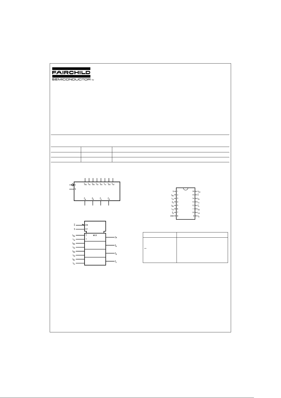
Logic Symbols Connection Diagram
Pin Descriptions
Pin Names Description
I
0a–I0d
Source 0 Data Inputs
I
1a–I1d
Source 1 Data Inputs
E
Enable Input
S Select Input
Z
a–Zd
Outputs
DS011352-1
IEEE/IEC
DS011352-3
Pin Assignment
for SOIC JEDEC and EIAJ
DS011352-2
May 1998
74LVQ157 Low Voltage Quad 2-Input Multiplexer
© 1998 Fairchild Semiconductor Corporation DS011352 www.fairchildsemi.com
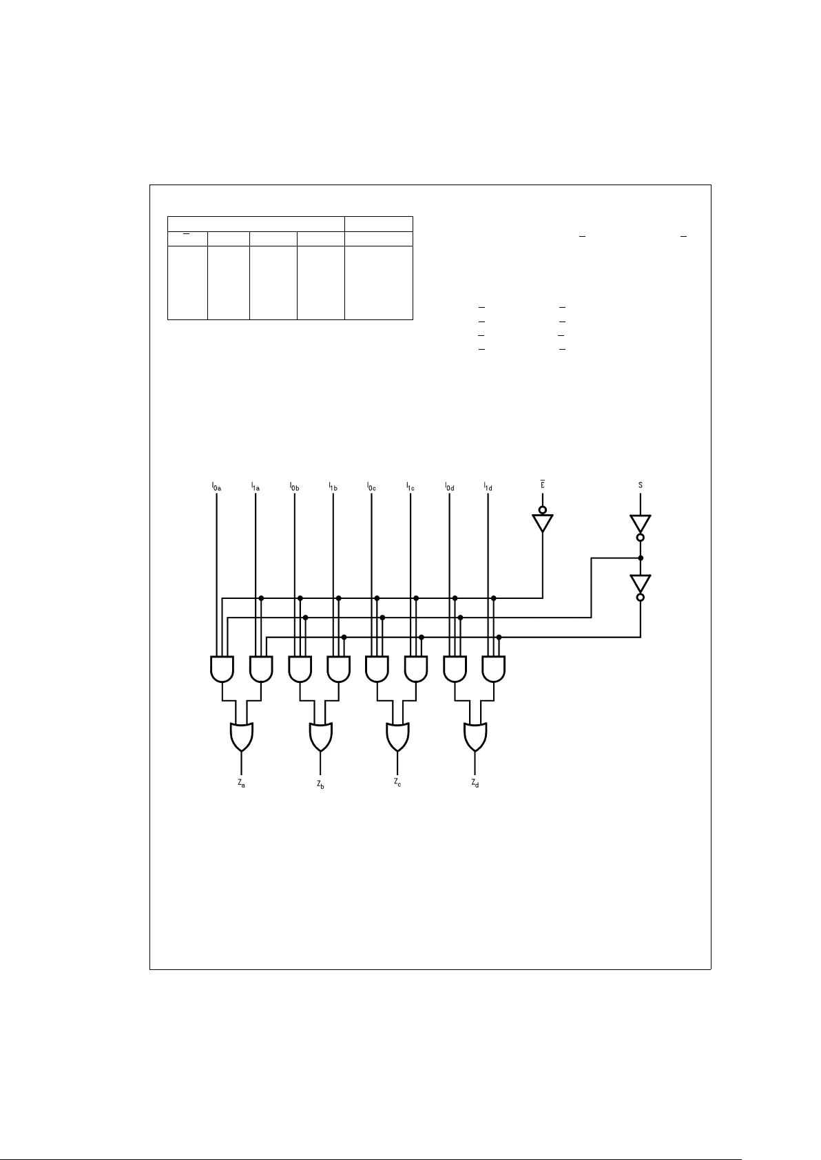
Truth Table
Inputs Outputs
E
SI0I
1
Z
HX X X L
LH X L L
LH X H H
LL L X L
LLH X H
H=HIGH Voltage Level
L=LOW Voltage Level
X=Immaterial
Functional Description
The LVQ157 is a quad 2-input multiplexer. It selects four bits
of data from two sourcesunder the control of a common Select input (S). The Enable input (E) is active-LOW.When Eis
HIGH, all of the outputs(Z) are forced LOW regardless of all
other inputs. The LVQ157 is the logic implementation of a
4-pole, 2-position switch where the position of the switch is
determined by the logic levels supplied to the Select input.
The logic equations for the outputs are shown below:
Z
a
=
E
•
(I
1a
•
S+I
0a
•
S)
Z
b
=
E
•
(I
1b
•
S+I
0b
•
S)
Z
c
=
E
•
(I
1c
•
S+I
0c
•
S)
Z
d
=
E
•
(I
1d
•
S+I
0d
•
S)
Acommon useof the LVQ157 is the moving of data from two
groups of registers to four common output busses. The particular register from which the data comes is determined by
the state of the Select input. Aless obvious use is as a function generator. The LVQ157can generateany fourof thesixteen different functions of two variables with one variable
common. This is useful for implementing gating functions.
Logic Diagram
DS011352-5
Please note that this diagram is provided only for the understanding of logic operations and should not be used to estimate propagation delays.
www.fairchildsemi.com 2
 Loading...