

Fairchild Semiconductor 74LCX32646 Datasheet
August 2001
Revised August 2001
74LCX32646
Low Voltage 32-Bit Transceiver/ Register
with 5V Tolerant Inputs and Outputs (Preliminary)
Preliminary
74LCX32646 Low Voltage 32-Bit Transceiver/Register with 5V Tolerant Inputs and Outputs (Preliminary)
General Description
The LCX32646 contains thirty-two non-inverting bidirectional registered bus transceivers with 3-STATE outputs,
providing multiplexed transmission of data directly from the
input bus or from the inte rnal storage re gisters. Each b yte
has separate control input s which can be shorted tog ether
for full 32-bit operation.The DIR
direction of data flo w through the dev ice. The CPAB
inputs load data into the registers on the LOW-to-
CPBA
n
HIGH transition (see Functional Description).
The LCX32646 is desi gned for low vol tage (2.5V or 3.3V )
V
applications with capability of interfacing to a 5V signal
CC
environment.
The LCX32646 is fabricated with an advanced CMOS tech-
nology to achieve high s peed operation while maintaining
CMOS low power dissipation.
inputs determine the
n
n
Features
■ 5V tolerant inputs and outputs
■ 2.3V–3.6V V
■ 5.2 ns t
■ Power down high impedance inputs and outputs
■ Supports live insertion/withdrawal (Note 1)
and
■
±24 mA Output Drive (V
■ Implements patented noise/EMI reduction circuitry
■ Latch-up performance exce eds 500 mA
■ ESD performance:
Human Body Model
Machine Model
■ Packaged in plastic Fine-Pitch Ball Grid Array (FBGA)
(Preliminary)
Note 1: To ensure the high-impedance state during power up or down, OE
should be tied to VCC through a pull-up res istor: the m inimu m value or t he
resistor is determin ed by the current-sourc ing capability of the driver.
specifications provided
CC
max (VCC = 3.3V), 20 µA ICC max
PD
> 2000V
> 200V
Ordering Code:
Order Number Package Number Package Description
74LCX32646GX
(Note 2)
Note 2: BGA package available in Tape and Reel only.
BGA114A
(Preliminary)
114-Ball Fine-Pitch Ball Grid Array (FBGA), JEDEC MO-205, 5.5mm Wide
[TAPE and REEL]
= 3.0V)
CC
© 2001 Fairchild Semiconductor Corporation DS500635 www.fairchildsemi.com
Preliminary
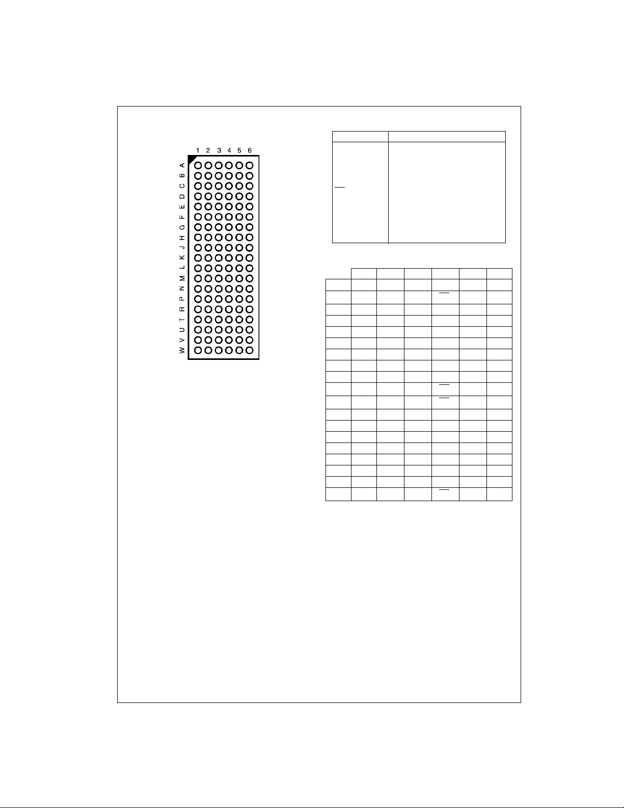
Connection Diagram
Pin Assignment for FBGA
74LCX32646
(Top Thru View)
Pin Descriptions
Pin Names Description
1A
- 1A
0
2A
- 2A
0
1B0 - 1B
2B
- 2B
0
OE
n
, CPBAnClock Pulse Inputs
CPAB
n
SAB
, SBA
n
DIR
n
Side A Inputs or 3-STATE Outputs
15
15
Side B Inputs or 3-STATE Outputs
15
15
Output Enable Inputs
Select Inputs
n
Direction Control Inputs
NC No Connect
FBGA Pin Assignments
123456
A 1A
B 1A21A1DIR1OE11B11B
C 1A41A3GND GND 1B31B4
D 1A
E 1A81A7GND GND 1B71B
F 1A101A9GND GND 1B91B
G 1A121A11V
H 1A131A14GND GND 1B141B
J 1A15SAB2CPAB2CPBA2SBA21B
K NC CPAB3DIR2OE2CPBA3NC
L 2A
M 2A22A1GND GND 2B12B
N 2A42A3V
P 2A62A5GND GND 2B52B
R 2A82A7GND GND 2B72B
T 2A102A9V
U 2A122A11GND GND 2B112B
V 2A132A14CPAB4CPBA42B142B
W 2A15SAB4DIR4OE4SBA42B
SAB1CPAB1CPBA1SBA11B
0
1A5V
6
SAB3DIR3OE3SBA32B
0
CCVCC
CCVCC
CCVCC
CCVCC
1B51B
1B111B
2B32B
2B92B
0
2
6
8
10
12
13
15
0
2
4
6
8
10
12
13
15
www.fairchildsemi.com 2
Preliminary
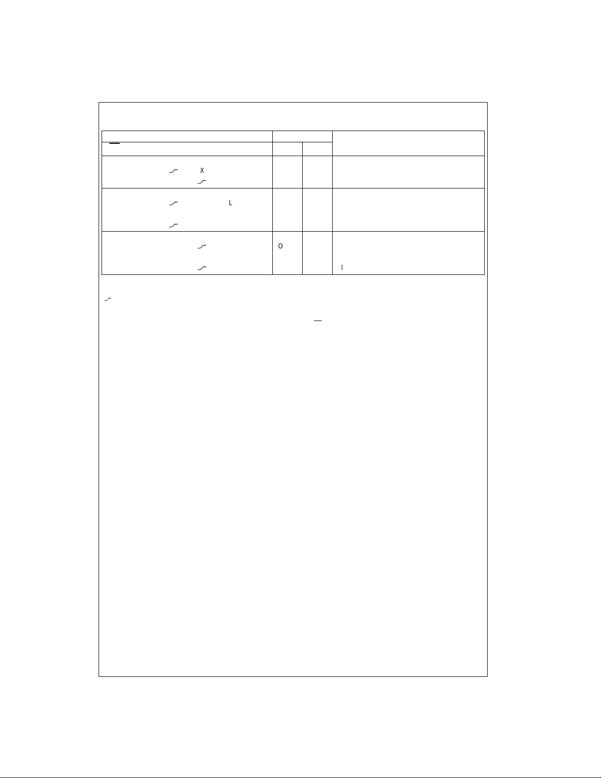
Truth Table
(Note 3)
OE
DIR1 CPAB1 CPBA1 SAB1 SBA1 1A
1
H X H or L H or L X X Isolation
H X
H X X
L H X X L X A
L H
L H H or L X H X A Register to B
L H
L L X X X L Bn to An — Real Time (Transparent Mode)
L L X
L L X H or L X H B Register to A
L L X
H = HIGH Voltage Level
L = LOW Voltage Level
X = Immaterial
= LOW-to-HIGH Transiti on
Note 3: Data I/O paths (1A and 1B: 0 - 7) is sh own . This a lso ap pli es to dat a I/O (1 A a nd 1B: 8 - 15) an d #2 co ntro l pins, to data (2A an d 2B : 0 - 7) an d #3
control pins, to data (2A and 2B: 8 - 15) and #4 control pins.
Note 4: The data output functions may be enabled or dis abled by various sig nals at the OE
i.e., data at the bus pins wi ll be stored on every LO W-to-HIGH transition of the appropriate clock inputs.
Inputs Data I/O (Note 4)
1B
0–7
X X X Input Input Clock An Data into A Register
X X Clock Bn Data Into B Register
X L X Input Output Clock An Data to A Register
X H X Clock An Data into A Register and Output to B
X L Output Input Clock Bn Data into B Register
X H Clock Bn into B Register and Output to A
0–7
n
and DIR inputs. Data input functions are al w ays enabled;
Output Operation Mode
to Bn — Real Time (Transparent Mode)
(Stored Mode)
n
(Stored Mode)
n
n
74LCX32646
n
3 www.fairchildsemi.com
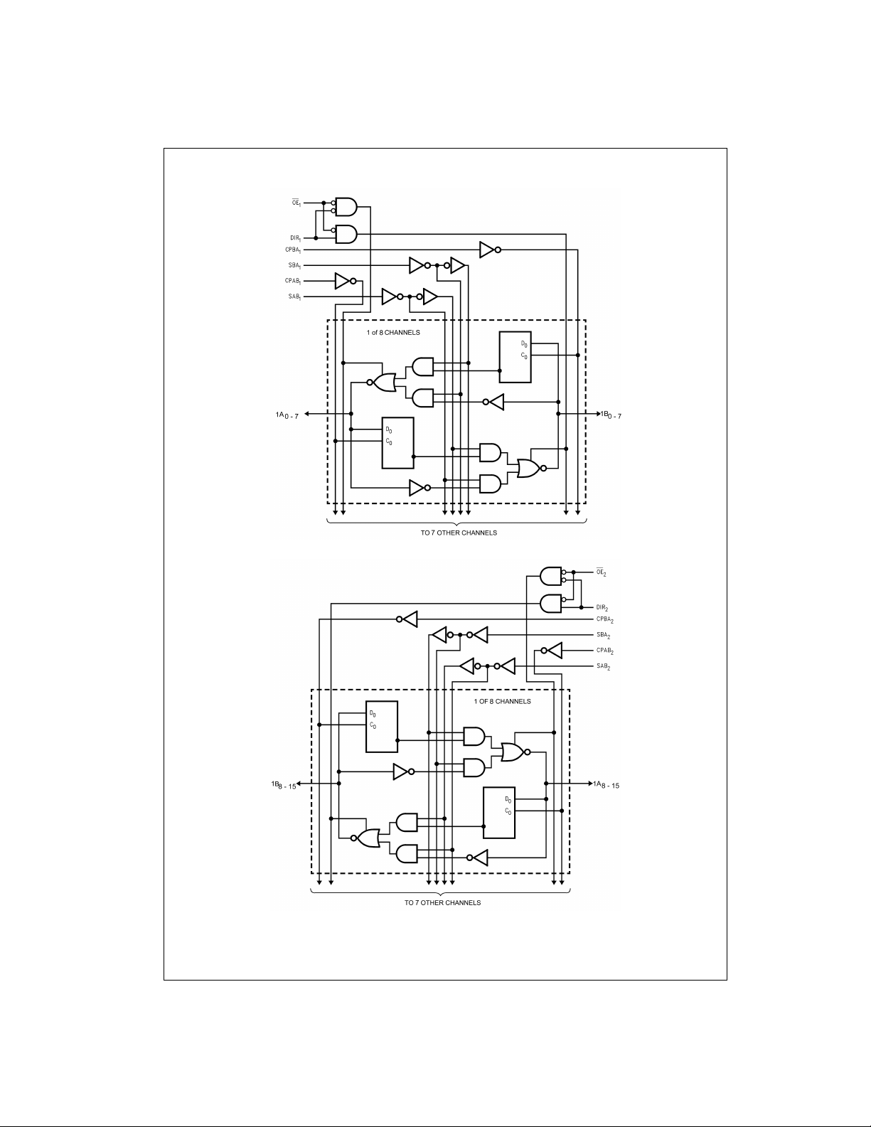
Logic Diagrams
74LCX32646
Preliminary
Please note that these diagrams are provided only for the un derstanding of logic operations and should not be used to estim at e propagation delays .
www.fairchildsemi.com 4
 Loading...