

Fairchild Semiconductor 74F640SCX, 74F640SC, 74F640PC Datasheet
© 1999 Fairchild Semiconductor Corporation DS010267 www.fairchildsemi.com
July 1989
Revised August 1999
74F640 • 74F645 Octal Bus Transceiver with 3-STATE Outputs
74F640 • 74F645
Octal Bus Transceiver with 3-STATE Outputs
General Description
These devices are octal bus transceivers designed for
asynchronous two-way data flow between the A and B busses. Both busses are capa ble of sinking 64 mA, have 3STATE outputs, and a common output enable pin. The
direction of data flow is d eterm ined by t he tran smit/ receive
(T/R
) input. The 74F645 is a high speed/low power version
of the 74F245. The 74F 640 is an inverting option of the
74F645.
Features
■ Designed for asynchronous two- way data flow between
busses
■ Outputs sink 64 mA
■ Transmit/receive (T/R
) input controls the direction of
data flow
■ 74F645 is a lower power, faster version of the 74F245
■ 74F640 is an inverting option of the 74F645
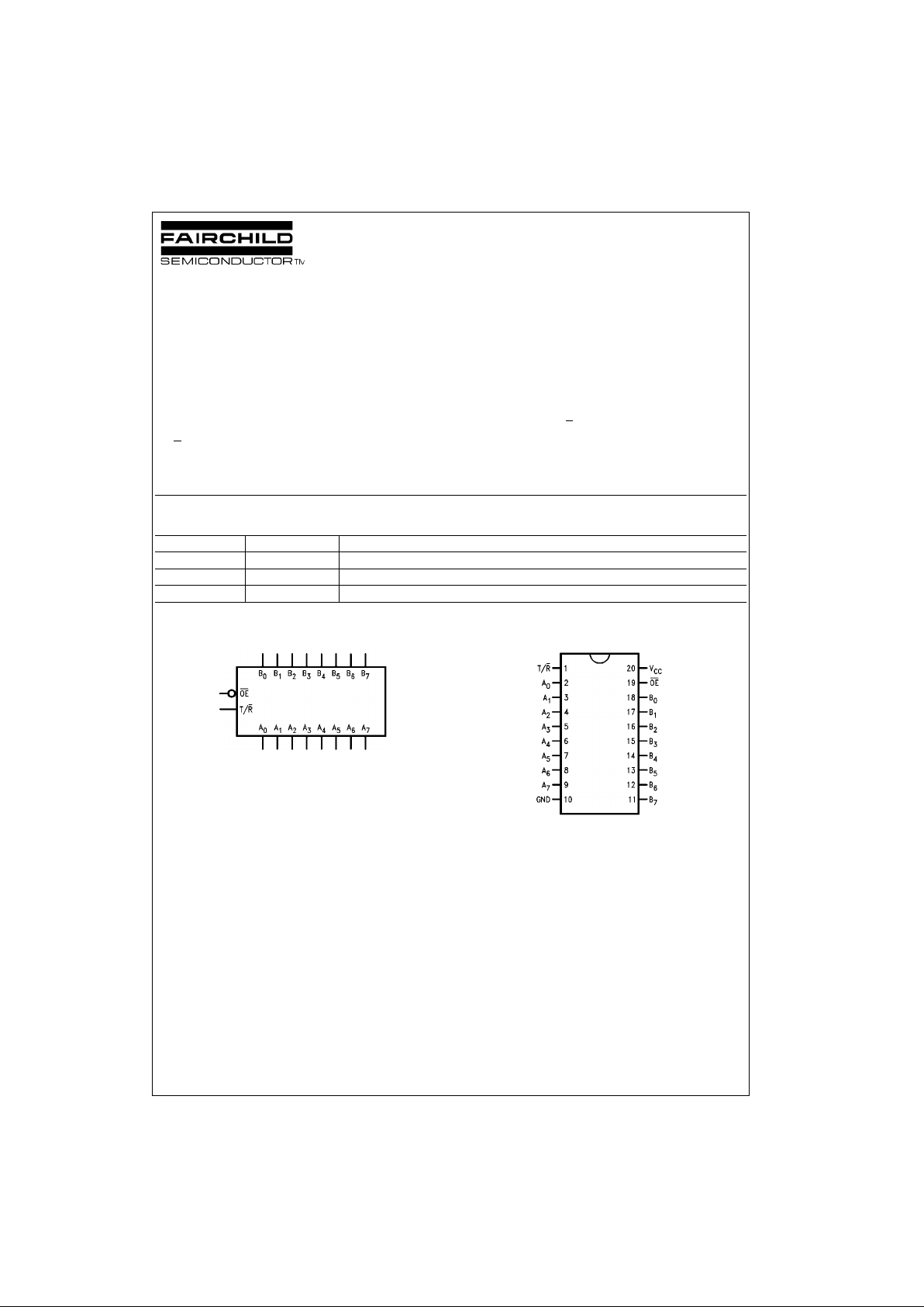
Ordering Code:
Devices also availab le in Tape and Reel. Specify by appending th e s uffix let t er “X” to the ordering code.
Logic Symbol Connection Diagram
Order Number Package Number Package Description
74F640SC M20B 20-Lead Small Outline Integrated Circuit (SOIC), JEDEC MS-013, 0.300 Wide
74F640PC N20A 20-Lead Plastic Dual-In-Line Package (PDIP), JEDEC MS-001, 0.300 Wide
74F645PC N20A 20-Lead Plastic Dual-In-Line Package (PDIP), JEDEC MS-001, 0.300 Wide
www.fairchildsemi.com 2
74F640 • 74F645
Unit Loading/Fan Out
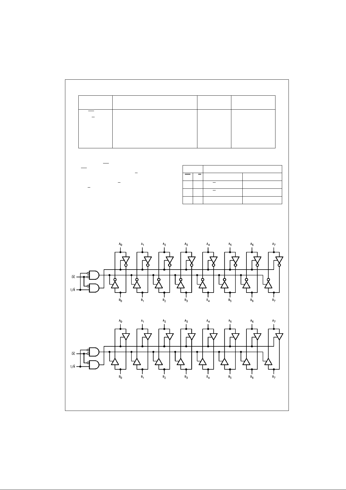
Functional Description
The output enable (OE) is active LOW. If the device is disabled (OE
HIGH), the outpu ts are in the high impedance
state. The transmit/receive input (T/R
) controls whether
data is transmitted from the A bu s to the B bus o r from th e
B bus to the A bus. When T/R
is LOW, B data is sent to the
A bus. If T/R
is HIGH, A data is sent to the B bus.
Function Table
H = HIGH Voltage Level
L = LOW Voltage Level
X = Don’t Care
Z = High Impedance State
Logic Diagram
74F640
74F645
Pin Names Description
U.L.
Input I
IH/IIL
HIGH/LOW
Output I
OH/IOL
OE
Output Enable Input (Active LOW)
1.0/1.0 20 µA/−0.6 mA
T/R
Transmit/Receive Input 1.0/1.0 20 µA/−0.6 mA
A
0–A7
Side A Inputs or 3.5/0.667 70 µA/−0.4 mA
3-STATE Outputs 600/106.6 −12 mA/64 mA
B
0–B7
Side B Inputs or 3.5/0.667 70 µA/−0.4 mA
3-STATE Outputs 600/106.6 −12 mA/64 mA
Inputs Outputs
OE
T/R 74F640 74F645
L L Bus B
data to Bus A Bus B data to Bus A
L H Bus A
data to Bus B Bus A data to Bus B
HX Z Z
 Loading...