

Fairchild Industrial Products 63 User Manual

A
A
Model
63
Model 63 Pneumatic Filter Regulator
Features
• The no-brass construction is well suited to
harsh environments.
• Internal and external epoxy finish for
superior corrosion resistance
• Non-bleed design to reduce consumption
• Integral Relief Valve
• A Gauge Port provides convenient
Diaphragm
ssembly
Bonnet
pressure gauge mounting.
• The standard 5-micron filter minimizes
Body
internal contamination.
• The Filter Dripwell contains a Drain Plug
to easily drain trapped liquids.
• Standard Tapped Exhaust
• Soft Relief Seat minimizes air loss
• Canadian Registration Number (CRN)
Drain
Cock
Dripwell
Assembly
certification for all territories and
provinces.
Operating Principles
When you turn the Adjustment Screw to a
specific setpoint, the Spring exerts a
downward force against the top of the
Diaphragm Assembly. This downward
force opens the Supply Valve. Output
pressure flows through the Outlet Port and
the
passage to the Control Chamber where it
creates an upward force on the bottom of
the Diaphragm Assembly.
When the setpoint is reached, the force of
the Spring that acts on the top of the
Diaphragm Assembly balances with the
force of output pressure that acts on the
bottom of the Diaphragm Assembly and
closes the Supply Valve.
When the output pressure increases
above the setpoint, the Diaphragm
[200.3]
EXHAUST
1/4 NPT
[1/4 BSPT]
EXHAUST
INLET/OUTLET
1/4 NPT,
[1/4 BSPT] OR
[32.6]
1.29
[1/4 BSPP]
MAX KNOB
7.88
]
.1
[8
0.32
U
R
H
T
G
IN
T
N
U
O
M
2
(2) MOUNTING HOLES
1/4-20 UNC-2B X 0.38 DP
[M6-1 X 9.5 DP]
BACK SIDE
[31.8]
1.25
Å
INLET
S
E
L
O
H
MOUNTING
Assembly moves upward to close the
Supply Valve and open the Exhaust Valve.
Output
pressure flows through the Exhaust Valve
and out of the Exhaust Vent on the side of
Note: Pipe plug is included
the unit until it reaches the setpoint.
[65]
2.56
[48.5]
1.91
KNOB
[57.2]
2.25
MOUNTING HOLES
BACK SIDE
[71.9]
2.83
[19.1]
HEX TAMPERPROOF
0.75
[7.9]
0.31
SCREW
[38.7]
1.52
OUTLET
[6]
0.24
DRAINCOCK
[75.1]
[68.9]
[18]
2.96
2.71
0.71
[208]
7.52 SCREW ADJUST
[191.1]
TAMPERPROOF
8.19
26
800-334-8422
Model 63 Pneumatic Filter Regulator
0
20
4
0
60
8
0
100
120
140
-5 0 5 10 15 20 25 30 35 40 45
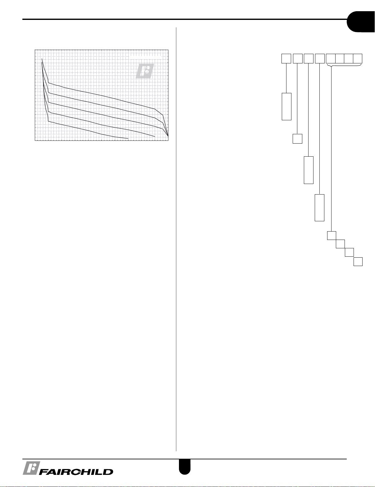
Supply Pressure = 150psig
Air Flow, SCFM
Output Pressure, PSIG
Flow Characteristics
F
airchild Model 63252
Setpoint= 90 psig
S
etpoint= 75 psig
Setpoint= 60 psig
Setpoint= 45 psig
Setpoint= 30 psig
echnical Information
T
Catalog Information
Catalog Number 6 3 2
Pressure Range
2
psig [BAR] (kPa)
0.5-30 [0.03-2] (3-200) . . . . . . .
1-60 [0.07-4] (7-400) . . . . . . .
2-120 [0.14-8] (14-800) . . . . . .
Port Size
1/4” . . . . . . . . . . . . . . . . . . . . . . . . . . . . . . . . . . . . . .
Port Thread
NPT . . . . . . . . . . . . . . . . . . . . . . . . . . . . . . . . . . . . . . . . .
BSPP . . . . . . . . . . . . . . . . . . . . . . . . . . . . . . . . . . . . . . . .
BSPT . . . . . . . . . . . . . . . . . . . . . . . . . . . . . . . . . . . . . . . . .
Actuator
Knob . . . . . . . . . . . . . . . . . . . . . . . . . . . . . . . . . . . . . . . . . . . . .
Screw . . . . . . . . . . . . . . . . . . . . . . . . . . . . . . . . . . . . . . . . . . . .
Tamper Proof . . . . . . . . . . . . . . . . . . . . . . . . . . . . . . . . . . . . . .
3
4
5
2
A
Model
63
N
H
U
K
S
T
Specifications
Supply Pressure
250 psig, [17BAR], (1700 kPa) Maximum
Flow Capacity (SCFM)
25 (42.5 m3/HR) @ 100 psig, [7 BAR], (700 kPa) supply
and 20 psig, [1.5 BAR], (150 kPa) setpoint
Exhaust Capacity (SCFM)
0.8 (1.36 m
[.35 BAR], (35 kPa) above 20 psig, [1.5 BAR], (150 kPa)
setpoint. (0.8 scfm for 120 # unit)
Maximum Supply Pressure
250 psig, [14 BAR], (1400 kPa)
3
/HR) where downstream pressure is 5 psig,
Options
Stainless Steel Trim/Drain . . . . . . . . . . . . . . . . . . . . . . . . . . . . . . . . .
Screen in Exhaust Port . . . . . . . . . . . . . . . . . . . . . . . . . . . . . . . . . . . . . . .
Quick Bleed Valve . . . . . . . . . . . . . . . . . . . . . . . . . . . . . . . . . . . . . . . . . . . . . . .
2” Pressure Gauge Option (NPT Only) . . . . . . . . . . . . . . . . . . . . . . . . . . . . . . . . . .
S
M
Installation Instructions
For installations instructions, refer to the Fairchild Model 63
Pneumatic Filter Regulator Instruction, Operation and
Maintenance Instructions, IS-10000063.
C
G
Consumption
Undetectable
Supply Pressure Effect
Less than 1.25 psig, [.09 BAR], (9 kPa) change for
100 psig, [7.0 BAR], (700 kPa) change in supply pressure
(1.90 psig for 120 # unit)
Sensitivity
1” (2.50 cm) Water Column
Temperature Range
o
-40
Fto + 160oF, (-40oC to+71oC)
Materials of Construction
Body and Housing . . . . . . . . .Epoxy Coated Aluminum
Trim . . . . . . . . . . . . .Stainless Steel, Nickel Plated Steel
Elastomers . . . . . . . . . . . . . . . . . . . . . . . . . . . . . .Nitrile
27
800-334-8422
www.fairchildproducts.com
 Loading...