

Page 1
FAIRCHILD TXI7800/TXI7850
EXPLOSION-PROOF I/P TRANSDUCERS
Installation,Operation and Maintenance Instructions
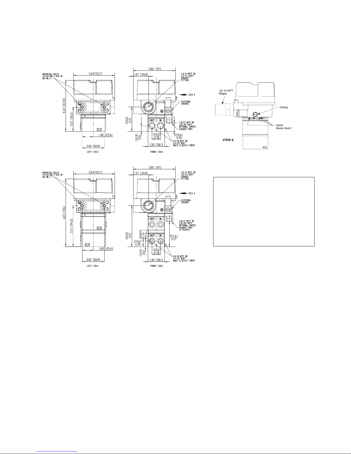
Figure 2. TXI7800/TXI7850 Outline Dimensions.
Standard Range Unit
Extended Range Unit
Materials of Construction
Body and Housing . Cromate Treated
Aluminum
Orifice . . . . . . . . . . Aluminum
and Sapphire
Trim . . . . . . . . . . . . Stainless Steel, Brass
and Zinc Plated Steel
Sintered Elements . Stainless Steel
Elastomers . . . . . . .Nitrile
Finish . . . . . . . . . . . Epoxy Powder Coating
NOTE: Unused IN and OUT Ports are plugged
.
GENERAL INFORMATION
The Model TXI7800/TXI7850 Explosion-Proof I/P Transducer transmits a pneumatic signal which is linearly proportional to a DC
input signal from electronic control devices. The Transducer uses low powered microelectronics and pressure feedback control
to provide a stable, accurate pneumatic output for the operation of valve actuators.
INSTALLATION
The Model TXI7800/TXI7850 can be mounted directly onto a flat surface using the two tapped mounting holes in the mounting
face of the housing. For more information, see Figure 2.
TXI7800/TXI7850, Installation with the "N" Option.
NOTE: For Hazardous Location in Potentially Explosive Atmosphere Installations
1. Tapped exhaust required for installation in Class 1, Division 2/Zone 2 (European Union) classified locations with
group D/Group IIA (European Union) gases such as Natural Gas and Methane-Industrial as the pressure supply medium.
2. The explosion-proof pipe nipple seal (N option) supplied with this unit is an integral component of the design safety
of this version and must not be removed. Use caution to avoid marring the threads on the pipe nipple which voids the
explosion-proof integrity of the device.
3. Gases used as the pressure supply medium in hazardous location applications must be compatible with the elastomer indicated in Materials of Construction.
A mounting Kit is available to mount the TXI7800/TXI7850 on a flat surface or on a 2" pipe. For more information, see Figure 3.
MAINTENANCE
To clean the Orifice, use the following procedure:
1. Shut off the valve that is supplying air to transducer. It is not necessary to remove the Transducer from the air line.
2. Remove the Orifice Assembly from the unit. For more detailed information see View A.
3. Clean with alcohol and dry with compressed air.
4. Lubricate O-Rings on Orifice Assembly (4) with silicone grease or equivalent lubricant before reassembling.
NOTES:
Parts must be completely dry before reassembling.If the standard maintenance procedure does not correct the trouble, a service
kit containing a replacement diaphragm and orifice assembly is available, see Figure 5.
Page 2
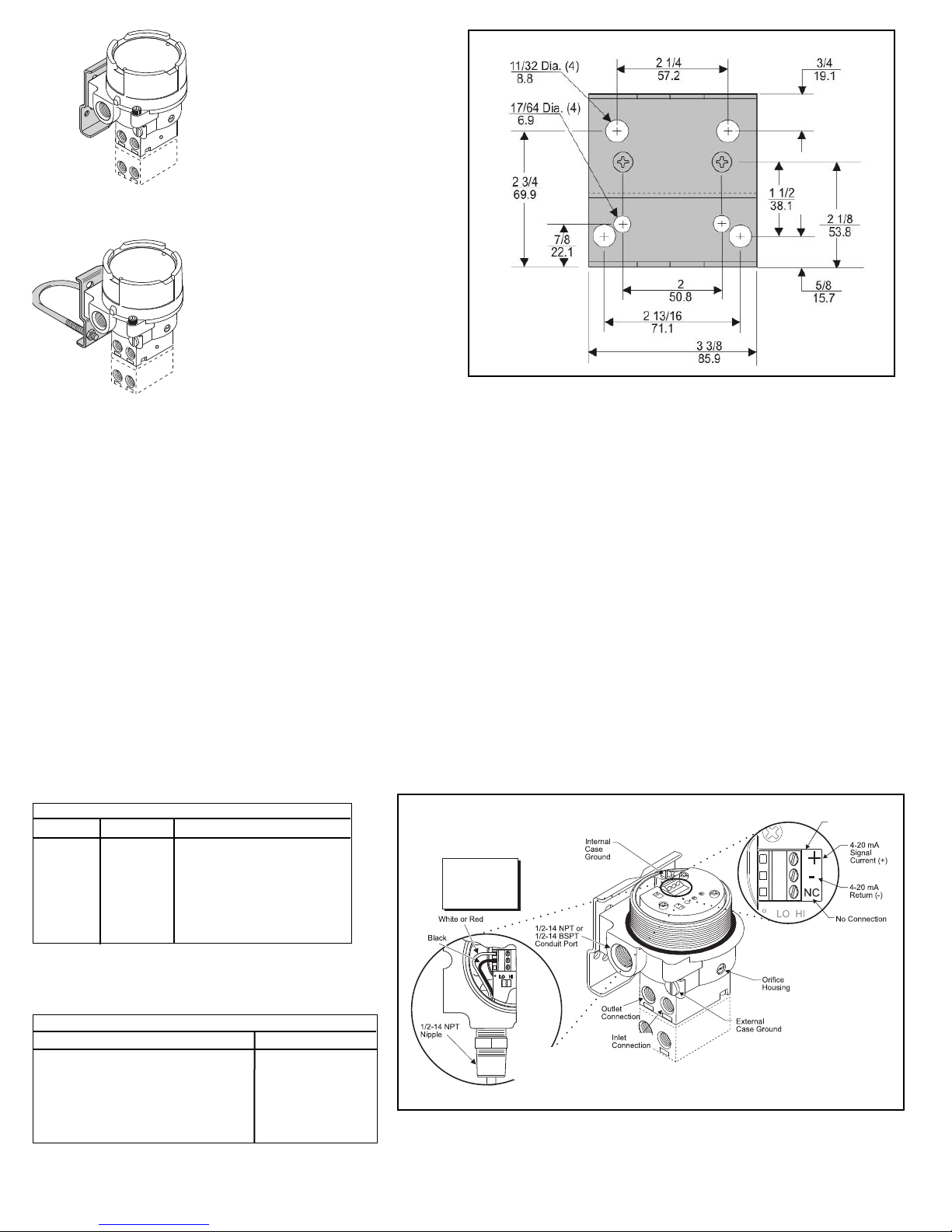
Table1. Hazardous Location Wiring Practices
Country Agency Code
U.S. FM ANSI/ISA RP 12.6
ANSI/NFPA70
Canada CSA CEC Part1
Europe ATEX EN 50 039, EN 60079-
14, IEC 60079-14
Australia SAA AS/NZS 3000, AS2381.1
Table 2. Intrinsically Safe Connections
Underwriting Group Drawing Number
FM (Factory Mutual) EC- 18970
CSA (Canadian Standards Assoc.) EC- 18971
ATEX EC- 18972
SAA (Standard Australia Assoc.) EC- 19271
For "U" option BSPT
Mounting Kit 19021-2
Includes the following:
Stainless Steel Mounting Bracket
Two M6 X 12mm Screws
2" Pipe Clamp
Panel / Wall
Mounting
Configuration
Mounting Kit 19021-1
Includes the following:
Stainless Steel Mounting Bracket
Two 1/4-20 x 7/16" Screws
2" Pipe Clamp
Figure 3. Mounting Kit 19021-1. (Sold Separately)
2" Pipe Mounting
Configuration
Pneumatic Connections
Clean all pipelines to remove dirt and scale before installation.
Apply a minimum amount of pipe compound to the male threads of the fitting only. Do not use teflon tape as a sealant. Start with the third
thread back and work away from the end of the fitting to avoid the possibility of contaminating the transducer. Install the transducer in the air
line. The inlet and outlet ports are labeled on the side of the transducer. Tighten connections securely. Avoid undersized fittings that will limit
the flow through the transducer and cause a pressure drop downstream. For detailed information, see Figure 2. “TXI7800/TXI7850 Outline
Dimensions” on page 1.
Electric Connections
Make connections to the Terminal Block through the 1/2-14 NPT Conduit Port in the base of the housing as shown below in Figure 4.
“Electrical Connections”.
NOTE: Instrument quality air, per ISA Standards S7.3-1981, is required. Use a filter, ahead of the transducer, to remove dirt and
liquid in the air line. If an air line lubricator is used, it MUST be located downstream, beyond the transducer.
The user is responsible for insuring that the environment in which the unit will be installed, and the operating gas, is compatible with the materials in the transducer.
Wiring in Hazardous Areas
Wiring in hazardous areas should be performed in
accordance with T_ _able 1. and any local codes
that apply.
Intrinsically Safe Connections
Refer to the latest revision of the indicated drawing.
Figure 4. Electrical Connections.
2
Terminal
Block(TB1)
NOTE:
TappedExhaust
Option“E”
Requiredwith
NippleOption“N”
“N”Option
NaturalGas
ApprovalOnly
Page 3

CALIBRATIONS / ADJUSTMENTS
Equipment Required for Calibration:
• Pneumatic Supply capable of delivering up to 150 psig.
• Current Supply capable of delivering up to 30 mA.
• Pressure Gage capable of a digital readout up to 50 psig with an accuracy of .1%.
• Digital Volt Meter capable of a readout up to 30 mA with an accuracy of .02%.
FULL RANGE OPERATION
Lo/Hi Span Adjustment
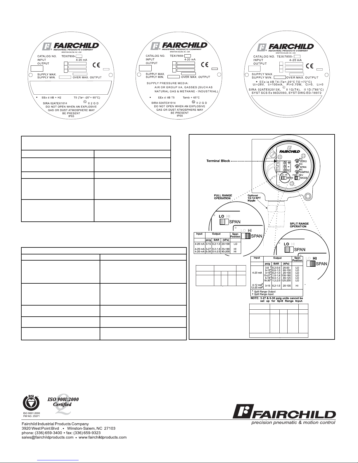
Set the Lo/Hi Span switch to the required position for needed output and supplied MA input. For more detail information, see Figure 6.
“TXI17800/TXI7850 Calibration Configuration”.
Forward Acting Mode Adjustment
Set Fwd/Rev Mode switch to Forward position.
Forward Acting Calibration
1. Apply the minimum input signal to the Terminal Block and adjust the Zero screw for minimum output presure.
2. Apply the maximum input signal to the Terminal Block and adjust the Span screw for maximum output pressure.
3. Repeat steps 1-2 until the desired output range is obtained.
Reverse Acting Mode Adjustment
Set Fwd/Rev Mode switch to the Reverse position
Reverse Acting Calibration
1. Apply the maximum input signal to the Terminal Block and adjust the Zero screw for minimum output pressure.
2. Apply the minimum input signal to the Terminal Block and adjust the Span screw for maximum output pressure.
3.Repeat steps 1-2 until the desired output range is obtained.
SPLIT RANGE OPERATION
Lo/Hi Span Adjustment
Set the Lo/Hi Span switch to the required position for needed output and supplied MA input. For more detail information, see
Figure 6 “TXI7800/TXI7850 Calibration Configuration”.
Forward Acting Mode Adjustment
Set Fwd/Rev Mode switch to Forward position.
Forward Acting Calibration
1. Apply the minimum input signal to the Terminal Block and adjust the Zero screw for minimum output presure.
2. Apply the maximum input signal to the Terminal Block and adjust the Span screw for maximum output pressure.
3. Repeat steps 1-2 until the desired output range is obtained.
Reverse Acting Mode Adjustment
Set Fwd/Rev Mode switch to the Reverse position
Reverse Acting Calibration
1. Apply the maximum input signal to the Terminal Block and adjust the Zero screw for minimum output pressure.
2. Apply the minimum input signal to the Terminal Block and adjust the Span screw for maximum output pressure.
3. Repeat steps 1-2 until the desired output range is obtained.
Additional Adjustments
Damping Adjustment
The Damping Adjustment is used so that the transducer can be tuned for optimum response and stability in a particular application.
For best performance start Damping Adjustment at maximum adjustment (fully clockwise). Gradually turn counterclockwise until
slight oscillation occurs and then turn back clockwise until oscillation is minimized. Turn damping adjustment clockwise to increase damping
function.
ATEX Directive- Special Conditions for Sale
The enclosure is manufactured from aluminum alloy. In rare cases, ignition sources due to impact and friction sparks could occur. This shall
be considered when the equipment is installed in locations that specifically require Group II, category 1G equipment.
3
Page 4
HAZARDOUS AREA SPECIFICATIONS
ATEX Directive Nameplates
Table 1. Trouble-Shooting
Problem Solution (check)
No Output Supply Pressure
Clogged Orifice
Leakage Connections
Low or Improper Zero and Span Adjust
Span Adjust Supply Pressure Low
Output Leakage
Erratic Operation DC Signal
Loose Wires or Connections
Liquid in Air Supply
WARNING:
Failure of Transducer could result in output pressure increasing to supply
pressure possibly causing personal injury or damage to equipment.
Service Kits for TXI7800/TXI7850
Series Ranges
Standard Range Unit
TEXI/TAXI 3-15 psig, [0.2-1.0 Bar], (20-100 Kpa)
Kit part no. 19268-1 3-27 psig, [0.2-1.8 Bar], (20-180 Kpa)
6-30 psig, [0.4-2.0 Bar], (40-200 Kpa)
Standard
TCXI/TFX 3-15 psig, [0.2-1.0 Bar], (20-100 Kpa)
Range
Kit part no. 19268-2 3-27 psig, [0.2-1.8 Bar], (20-180 Kpa)
Unit
6-30 psig, [0.4-2.0 Bar], (40-200 Kpa)
Extended Range Unit
T*XI 0-30 psig, [0.0-2.0 Bar], (0-200 Kpa)
Kit part no. 19268-14
T*XI 0-60 psig, [0.0-4.0 Bar], (0-400 Kpa)
Extended
Kit part no. 19268-15
Range
T*XI 0-120 psig, [0.0-8.0 Bar], (0-800 Kpa)
Units
Kit part no. 19268-16
Figure 5.
Figure 6.
TXI7800/TXI7850 Calibration Configuration
LEGAL NOTICE:
The information set forth in the foregoing Installation, Operation and Maintenance Instructions shall not be modified or amended in any respect without prior written consent of Fairchild Industrial Products Company. In addition, the information set forth
herein shall be furnished with each product sold incorporating Fairchild's unit as a component thereof.
IS-500TXI78
REV 08/06
Litho in USA
Input
4-20 mA, 0-5, 1-5,
0-10 & 1-9 VDC
Output
psig BAR (kPa)
0-30 0-2 0-200 HI
0-60 0-4 0-400 HI
0-120 0-8 0-800 HI
Span
Position
Input
psig
0-151 0-1 1 0-1001 LO
Split Range Output.
15-30 1 1-2 1 100-200 1 LO
0-301 0-2 1 0-2001 LO
30-60 1 2-4 1 200-400 1 LO
0-601 0-4 1 0-4001 LO
60-1201 4-8 1 400-8001 LO
4-20 mA, 0-5, 1-5,
0-10 & 1-9 VDC
1
Output
BAR
(kPa)
Span
Position
 Loading...