

www.fairchildsemi.com
TinyCalc™ User’s Guide (Excel® 07 Version)
Introduction
TinyCalc™ is a Microsoft® Excel®-based calculator created to simplify the design of TinyBuck™-based regulators.
TinyBuck™ products are integrated synchronous buck regulators with one high-side and one low-side MOSFET and a
controller / driver integrated in one 5x6mm molded leadless package (MLP).
The last digit in the part number signifies the current rating of the product. This calculator covers designs with FAN2103,
FAN2106, FAN2108, FAN2110, FAN21SV04, and FAN21SV06 regulators. Regulators with SV in the part numbers have a
built-in 5V regulator.
This document describes how to configure Excel 07 so this calculator can work without errors. This guide explains how to use
the TinyCalc™ calculator to choose external components for designs once the input and output conditions are provided.
Video Instructions
If you would prefer to watch an online video, click on the following link: “TinyCalc Setup Video”
Before Opening TinyCalc™
Add-in installation and Macro security selections must be set up
before opening TinyCalc™.
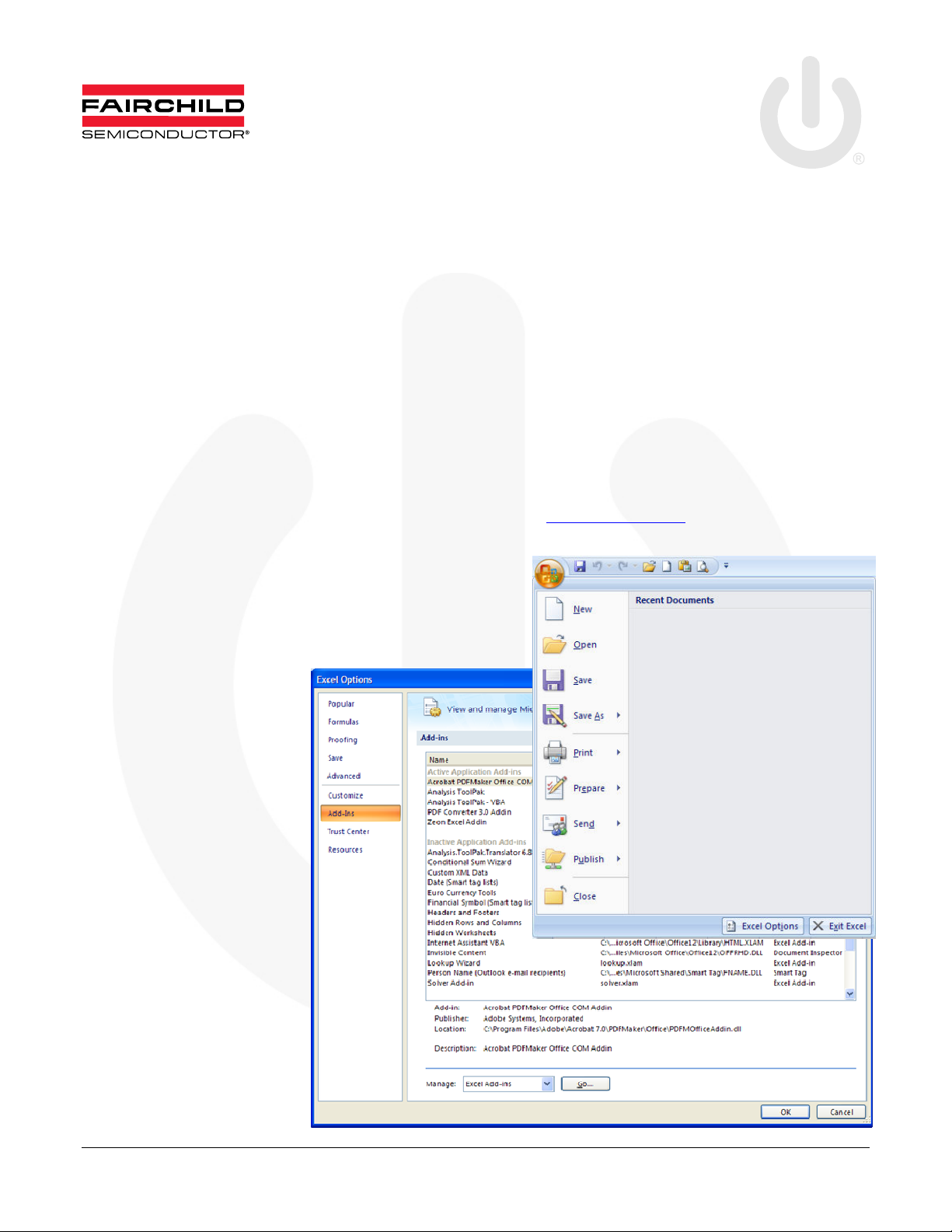
Check for Installed Add-in(s)
1. Open a new (blank) Excel
worksheet.
2. Click on the Windows icon
at the top left.
3. This opens up a pop-up
window (at right).
4. Click on the Excel Options
button at the bottom of this
dialog box which opens the
Excel Options window.
5. Click on the Add-Ins tab on
the left side of Excel Options
window. This lists all the
Add-ins available.
6. Click on the drop-down
window next to Manage: at
the left bottom, select Excel
Add-ins, and then click on
the Go... button next to it.
7. This opens the Add-Ins
dialog box.
© 2010 Fairchild Semiconductor Corporation www.fairchildsemi.com
Rev. 1.0.2 • 8/31/11
AN-8022 APPLICATION NOTE
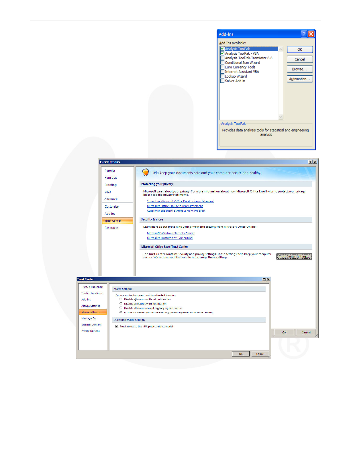
8. Select Analysis Toolpak and Analysis Toolpak – VBA. Disregard any
other add-ins.
9. Click OK and return to the new worksheet.
Note: If these two add-ins aren’t available in the Excel installation, it is
necessary to install the complete version of Excel.
Set Macro Security to Medium
TinyCalc™ works by embedding calculations as macros. Excel must be able
to run these macros for the application to function, but macros are considered
a security risk. Therefore, to run the macros, it is necessary to set your security
to medium (vs. high). With the new (blank) worksheet open, follow these steps
to set the macro security:
1.
Click the Windows icon located at the top left of the screen.
2.
Click on the Excel
Options button at the
bottom right of the
window.
3.
Select Trust Center
in the left side of
Excel options window
4.
Click on the Trust
Center Settings...
button at the right.
5.
Select the Macro
Settings in the left
pane of the Trust
Center window.
6.
Select the option:
Enable all macros
(which
opens all
files with
macros)
OR
Disable all
macros
with
notification
(which
prompts
each time a
file with
macros is opened).
7.
Click OK and click OK again on the last window open. This returns to the open blank sheet.
8.
Close the blank worksheet.
© 2010 Fairchild Semiconductor Corporation www.fairchildsemi.com
Rev. 1.0.2 • 8/31/11 2
AN-8022 APPLICATION NOTE
Working with TinyCalc™
1. Close any open Excel workbooks or worksheets.
2. Open the TinyCalc™ file delivered with this user guide. (The file name might change based on the revision – go to the
website to get the latest version of the calculator.)
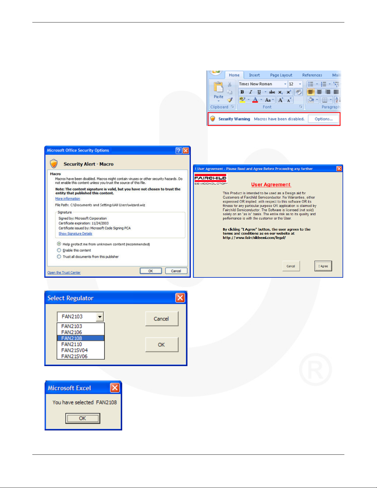
3. If macros are enabled, the file opens without any warning.
Skip to step 7.
4. If macros are disabled with notification, the file opens with a
security warning.
5. Click on the Options… button.
6. Select the option Trust all documents from this publisher and click OK. This closes the security alert and allows the
TinyCalc™ file to open.
7. When prompted to accept Fairchild’s terms and
conditions to use TinyCalc™, click the I Agree button.
8. In the Select Regular dialog box, select the regulator for your circuit design from the drop-down list and click OK.
9. Click OK to confirm the selection.
© 2010 Fairchild Semiconductor Corporation www.fairchildsemi.com
Rev. 1.0.2 • 8/31/11 3
AN-8022 APPLICATION NOTE
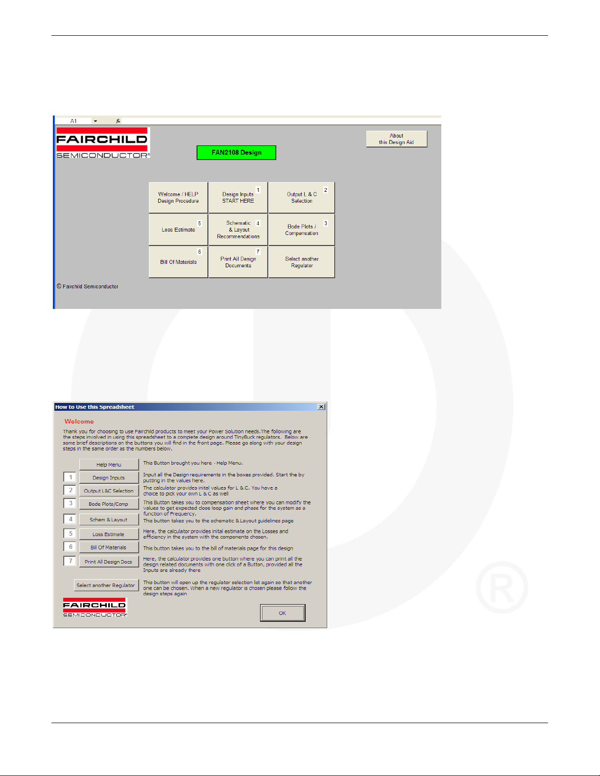
TinyCalc™ User Interface
The figure below is the “Front Page.” The numbers from 1 to 7 indicate the order of the steps involved in going through a
design. Once you are familiar with this calculator, you can skip to steps as needed by clicking on the appropriate button.
Clicking on the Welcome / Help / Design Procedure button opens the following dialog box. It is intended to provide firsttime users a brief description of the steps. It is recommended that you read this page when you use the calculator for the first
time. Click OK to return to the Front Page.
© 2010 Fairchild Semiconductor Corporation www.fairchildsemi.com
Rev. 1.0.2 • 8/31/11 4

AN-8022 APPLICATION NOTE
STEP 1 – Design Inputs
1. Click on the Design Inputs / START HERE button.
2. In the Input Parameters dialog box, enter the numbers for each of the design input variables.
Notes:
a. Press the tab key to move to the next field.
b. If you enter a unsuitable value, an error message appears providing the
appropriate range for the parameter. The control remains in the window
until an acceptable value is entered. The acceptable range is based on the
specifications of the regulator selected.
3. After all the values are entered, click OK. If all the variables are accepted as
valid inputs, the calculator closes and returns to the Front page.
© 2010 Fairchild Semiconductor Corporation www.fairchildsemi.com
Rev. 1.0.2 • 8/31/11 5

AN-8022 APPLICATION NOTE
STEP 2 – Output L&C Section
1. Click on the Output L&C Section button to open the Select the Right Inductor and Capacitor dialog box. The top two
boxes show suggested inductor and capacitor values.
2. Enter data for the inductor and capacitors (with combinations) for your design.
Note: If either of the ceramic OR electrolytic capacitors (bulk) is used alone, put zero (0) for parameters of the
capacitor not used. Use only numbers in these boxes.
3. After all the values are entered, press OK and return to the Front page.
© 2010 Fairchild Semiconductor Corporation www.fairchildsemi.com
Rev. 1.0.2 • 8/31/11 6

AN-8022 APPLICATION NOTE
STEP 3 – Bode Plots / Compensation
1. Click on the Bode Plots / Compensation button.
2. This opens a worksheet where you can select the
compensation components required to close the
control loop and ensure stable operation of the
converter. Before you are given control on this sheet
the first time, a message appears informing you that
changes affect the bill of materials. This is for your
information only.
3. Press OK to close this window and begin using the worksheet.
There are five columns in this worksheet, with rows 2 and 3 containing numbers. The second column is a set of
recommended values corresponding to the component designators in the pictures below the two rows. The third column is
where you can modify the numbers and see how the component values change phase margin.
There are buttons to the right to help you navigate from one sheet to other.
Go to Front Page returns you to the Front Page.
Go to Schematic accesses the typical application schematic for the part (same as step 4 from the Front Page).
Go to Bode Plots accesses graphs based on your component selections and values (see next page).
Print this Page sends the current sheet to the printer of your choice.
Copy Data & Pictures saves this data to the Windows clipboard in a picture format for you to paste into any other
Microsoft document.
© 2010 Fairchild Semiconductor Corporation www.fairchildsemi.com
Rev. 1.0.2 • 8/31/11 7

AN-8022 APPLICATION NOTE
The Bode Plots page displays plots for full load at minimum and maximum input voltage conditions.
There are text boxes that display the crossover frequency (bandwidth) and the phase margin for this design. Typically, it
is a good idea to have greater than 60° of phase margin and bandwidth less than one fifth (1/5) of the switching
frequency. Each time you return to this page, the new plot is based on the components selected.
There are buttons along the top to help you navigate from one sheet to other.
Go to Front Page returns you to the Front Page.
Go to Schematic accesses the typical application schematic for the part (same as step 4 from the Front Page).
Go to Compensation allows you to change or adjust any of the component values.
Print Bode Plots sends the current sheet to the printer of your choice.
Copy Bode Plots saves the plot to the Windows clipboard in a picture format for you to paste into any other
Microsoft document.
© 2010 Fairchild Semiconductor Corporation www.fairchildsemi.com
Rev. 1.0.2 • 8/31/11 8

AN-8022 APPLICATION NOTE
STEP 4 – Schematics & Layout Recommendations
Click on Schematics & Layout Recommendations button. The typical application diagram that appears changes based on
the controller chosen.
There are buttons at the right to help you navigate from one sheet to other.
Go to Front Page returns you to the Front Page.
Print Schematic sends the current diagram to the printer of your choice. All the component designators in the Bill of
Material sheet (Step 6) refer to this schematic.
Bode Plots / Compensation allows you to change or adjust any of the component values.
Layout Recommendations accesses general recommendation on how to layout switching regulators and provides a
copy of the evaluation board layout.
Copy Schematic saves the diagram to the Windows clipboard in a picture format for you to paste into any other
Microsoft document.
© 2010 Fairchild Semiconductor Corporation www.fairchildsemi.com
Rev. 1.0.2 • 8/31/11 9
AN-8022 APPLICATION NOTE
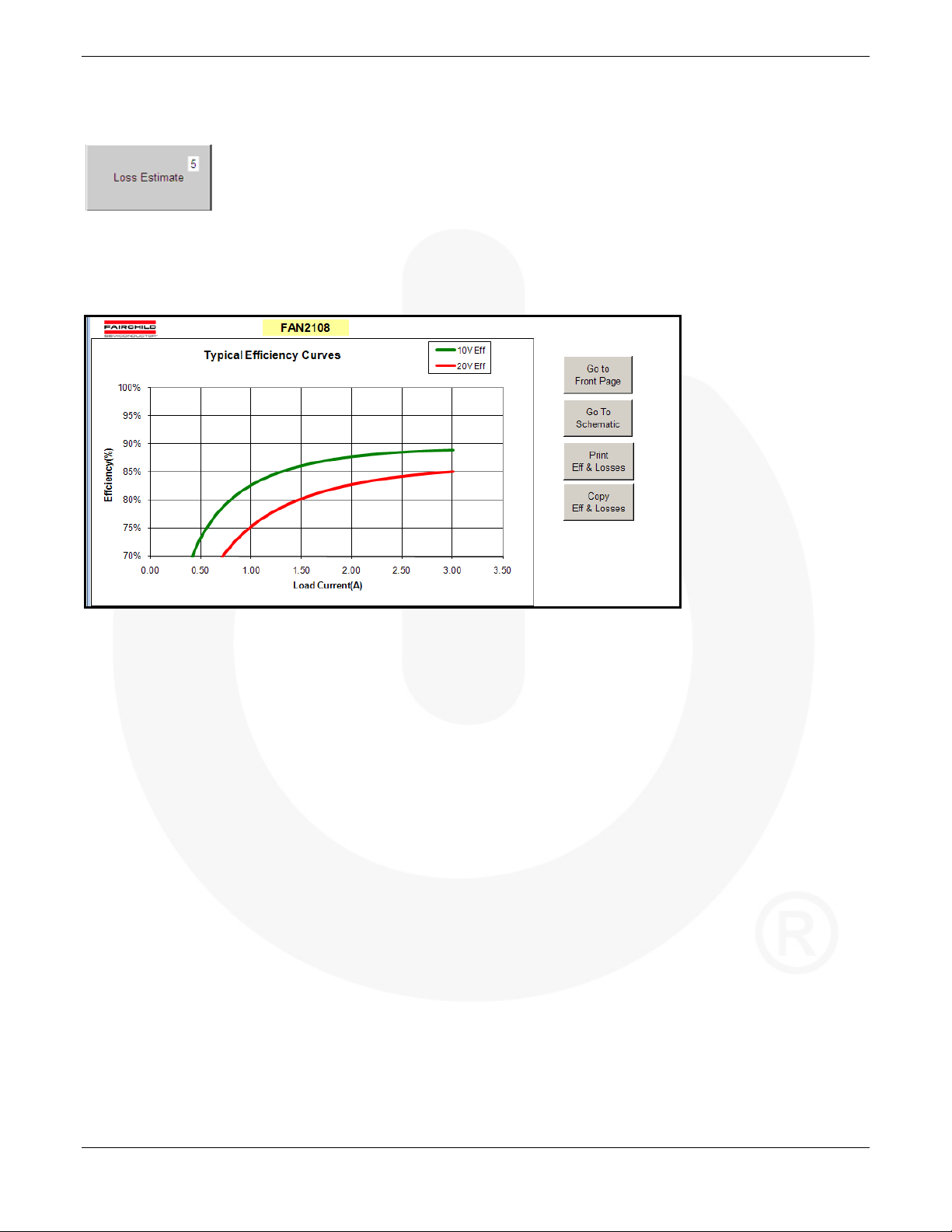
STEP 5 –Loss Estimate
Click on the Loss Estimate button. The calculator estimates efficiency and losses at minimum and maximum input voltage
conditions with the load current as a variable at room temperature in chart form.
There are buttons at the right to help you navigate from one sheet to other.
Go to Front Page returns you to the Front Page.
Go to Schematic accesses the typical application schematic for the part (same as step 4 from the Front Page).
Print Eff & Losses sends the current charts to the printer of your choice.
Copy Eff & Losses saves the charts to the Windows clipboard in a picture format for you to paste into any other
Microsoft document.
© 2010 Fairchild Semiconductor Corporation www.fairchildsemi.com
Rev. 1.0.2 • 8/31/11 10

AN-8022 APPLICATION NOTE
STEP 6 – Bill of Materials
1. Click on Bill of Materials button.
2. A dialog box that appears to make sure that you don’t jump into this section without entering right values for the inductor
and output capacitor. Press OK to proceed to the Bill of Materials worksheet or Cancel to return to the Front Page.
This sheet provides all the component values needed to build the design according to your selections and entered values. This
sheet includes any changes made in the “compensation” components as well as the inductor and output capacitors. There are a
few component manufacturers links for capacitors and inductors to help you find the right parts.
There are buttons along the top to help you navigate from one sheet to other.
Go to Schematic accesses the typical application schematic for the part (same as step 4 from the Front Page).
Print BOM sends the current worksheet to the printer of your choice.
Go to Front Page returns you to the Front Page.
Copy BOM saves the worksheet view to the Windows clipboard in a picture format for you to paste into any other
Microsoft document.
© 2010 Fairchild Semiconductor Corporation www.fairchildsemi.com
Rev. 1.0.2 • 8/31/11 11
AN-8022 APPLICATION NOTE
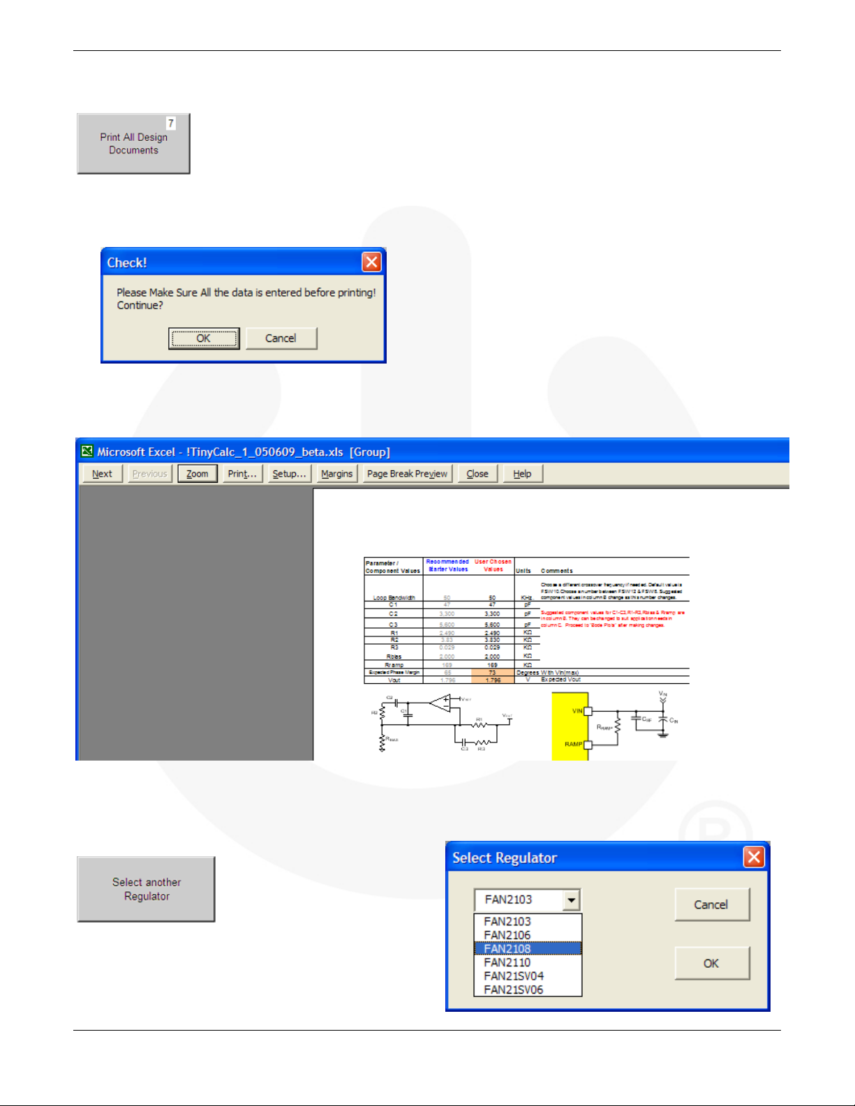
STEP 7 – Print All Design Documents
1. Click on the Print All Design Documents button.
2. A dialog box that appears to make sure that you don’t jump into this section without entering right values for the inductor
and output capacitor. Press OK to proceed to print preview or Cancel to return to the Front Page.
This enables you to print all the design documents once. This feature is helpful if you have this design saved and you
want to print the documents at all later time. This accesses the standard MSExcel print preview functionality.
3. Click Print… to select the printer and the number of copies to print.
After printing, the control returns to the Front Page.
Select Another Regulator
1. Click the Select Another Regulator Button to repeat the
process with a new regulator (see STEP 1).
Design Complete!
© 2010 Fairchild Semiconductor Corporation www.fairchildsemi.com
Rev. 1.0.2 • 8/31/11 12

AN-8022 APPLICATION NOTE
Related Datasheets
FAN2103 — TinyBuck™ 3A, 24V Input Integrated Synchronous Buck Regulator
FAN2106 — TinyBuck™ 6A, 24V Input Integrated Synchronous Buck Regulator
FAN2108 — TinyBuck™ 3-24V Input, 8A, High-Efficiency, Integrated Synchronous Buck Regulator
FAN2110 — TinyBuck™ 3-24V Input, 10A, High-Efficiency, Integrated Synchronous Buck Regulator
FAN21SV04 — TinyBuck™ 4A, 24V Single-Input Integrated Synchronous Buck Regulator
FAN21SV06 — TinyBuck™ 6A, 24V Input, Single Supply, Integrated Synchronous Buck Regulator
TinyCalc™ Calculator for the Design of TinyBuck™-Based Regulators
Notes:
Every effort has been made to ensure that TinyCalc is accurate and reliable; however, if a command throws a “Run-Time
Error,” closing and opening it resolves the issue.
Excel users who have been using Excel 97 through Excel 2003 who upgrade to Excel 2007 or 2010 may find the new ribbon
system confusing. If this is the case, Microsoft® has a released a free workbook that maps Excel 97-2003 commands to the
ribbon: Excel Ribbon Mapping Workbook that may be useful.
DISCLAIMER
FAIRCHILD SEMICONDUCTOR RESERVES THE RIGHT TO MAKE CHANGES W ITHOUT FURTHER NOTICE TO ANY PRODUCTS
HEREIN TO IMPROVE RELIABILITY, FUNCTION, OR DESIGN. FAIRCHILD DOES NOT ASSUME ANY LIABILITY ARISING OUT OF THE
APPLICATION OR USE OF ANY PRODUCT OR CIRCUIT DESCRIBED HEREIN; NEITHER DOES IT CONVEY ANY LICENSE UNDER ITS
PATENT RIGHTS, NOR THE RIGHTS OF OTHERS.
LIFE SUPPORT POLICY
FAIRCHILD’S PRODUCTS ARE NOT AUTHORIZED FOR USE AS CRITICAL COMPONENTS IN LIFE SUPPORT DEVICES OR SYSTEMS
WITHOUT THE EXPRESS WRITTEN APPROVAL OF THE PRESIDENT OF FAIRCHILD SEMICONDUCTOR CORPORATION.
As used herein:
1. Life support devices or systems are devices or systems which,
(a) are intended for surgical implant into the body, or (b) support
or sustain life, or (c) whose failure to perform when properly
used in accordance with instructions for use provided in the
labeling, can be reasonably expected to result in significant
injury to the user.
© 2010 Fairchild Semiconductor Corporation www.fairchildsemi.com
Rev. 1.0.2 • 8/31/11 13
2. A critical component is any component of a life support device
or system whose failure to perform can be reasonably expected
to cause the failure of the life support device or system, or to
affect its safety or effectiveness.
 Loading...