

Page 1
FAIRCHILD T6000 Electro-Pneumatic Transducers
Standard and Extended Ranges
Installation Instructions
GENERAL INFORMATION
The Model T6000 can be mounted directly onto a flat surface using two 10-32 screws.
The Model T6000 is supplied with a Mounting Kit 16799-1 for Panel or Wall Mounting. For detailed information,
see page 2.
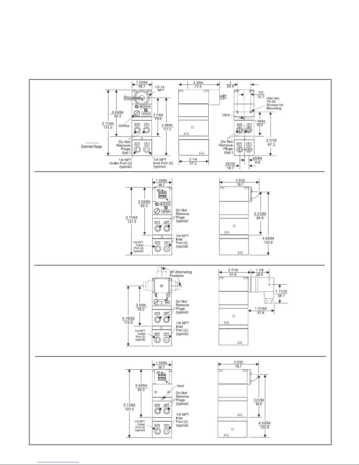
Figure 1. TA6000 Outline
Dimensions
Note: Unused IN and OUT
Ports are plugged (typical)
Figure 2. TT6000 Outline
Dimensions
Figure 3. TD6000 Outline
Dimensions
Figure 4. TR6000 Outline
Dimensions
Page 2
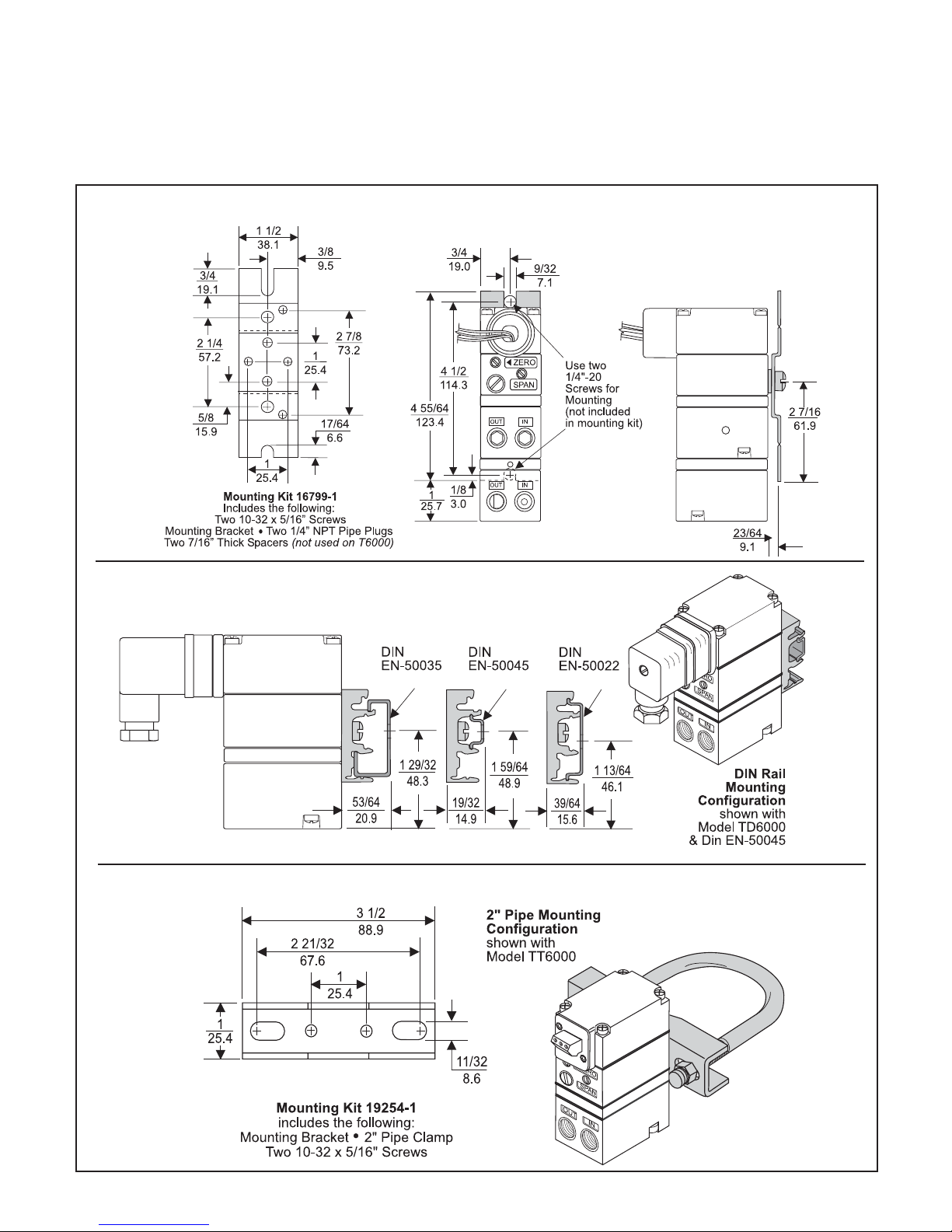
Installation
The Model T6000 is supplied with a DIN Rail Mounting Kit
16893. For detailed information, see Figure 6. A
Mounting Kit 19254-1 is available when installing the unit
on a 2" pipe, see Figure 7.
Figure 5. Mounting Kit 16799-1 (Included with Unit)
NOTE : The TR6000 Transducer is designed for use with
the TR Rack Kit. Physically, it is the same as the TT6000
(Terminal Block) Unit except that the terminal block has
been rotated to the rear. For detailed information, see
Figure 4. “TR6000 Outline Dimensions” on page 1.
Figure 6. DIN Rail Mounting Kit 16893 (Included with Unit)
Figure 7. Mounting Kit 19254-1 (Sold Separately)
2
Page 3

Pneumatic Connection
Clean all pipelines to remove dirt and scale before installation. Apply
a minimum amount of pipe compound to the male threads of the
fitting only. Do Not use teflon tape as a sealant. Start with the third
thread back and work away from the end of the fitting to avoid
contaminating the transducer. Install the transducer in the air line.
The inlet and outlet ports are labeled on the ends of the transducer.
Tighten connections securely. Avoid undersized fittings that will limit
the flow through the transducer and cause pressure drop down
stream.
MAINTENANCE
To clean the Orifice, use the following procedure:
1.
Shut off the valve that is supplying air to transducer.
It is not necessary to remove the Transducer from
the air line.
2.
Remove the Orifice Assembly from the unit. For
detailed information see Figure 1 “T6000 Calibration
Configuration on page 1.
NOTE:
Oil free air is required. Use a filter to remove dirt and
liquid in the air line ahead of the transducer. If an air
line lubricator is used, it MUST be located downstream to avoid interference with transducer performance.
The user is responsible for insuring that the environment in which the unit will be installed and the
operating gas are compatible with the materials in the
transducer.
Electric Connection
Make connections as shown in Figure 8.
CAUTION: Effective November 1997 (DATE CODE NE), the DIN
Connector terminal connections have been changed. The ground
connection has been moved from terminal #3 to the ( ) terminal.
When replacing an existing unit, correct wiring on the mating
connector.
Wiring in Hazardous Areas
Table 1. Hazardous Location Wiring Practices.
Country
U.S.
Canada
Europe
Agency
FM
CSA
ATEX
ANSI/ISA RP 12.6 & ANSI/NFPA 70
CEC Part 1
EN 50 039, EN 60079-14, IEC 60079-14
Code
Intrinsically Safe Connections
Table 2. Intrinsically Safe Installation Drawings.
Underwriting Group
FM (Factory Mutual)
CSA (Canadian Standards)
ATEX
Drawing Number
EC-16984
EC-18005
EC-18007
Limitations/Exceptions
Type 3R - TAF, TDF upright position
TFA - CL I, Div 2 wiring per NEC ANSI/NPFA 70 for installation
without wiring parameters. TDF, TTF, TRF require an enclosure.
For dry locations and voltages less than 60Vdc, TTF & TRF
units must be in an enclosure.
Where loop voltages exceed 60Vdc (dry locations) or 30Vdc
(potentially damp locations), the TTF and TRF versions
must be installed meeting the electrical shock and fire
protection requirements of ANSI/ISA S82.01.
3.
Clean with alcohol and dry with compressed air.
NOTES:
Parts must be completely dry before reassembling.
If the standard maintenance procedure does not
correct the trouble, install the appropriate Service
Kit below:
16798-1 (3-15, 3-27 & 6-30 psig
Standard Range)
18238-1 (0-30 psig Extended Range)
18239-1 (0-60 psig Extended Range)
18240-1 (0-120 psig Extended Range)
18039-1 (Explosion-Proof Base)
Service Kits also include Gasket, O-Rings, and
Membranes to replace "W" Option product.
TROUBLE-SHOOTING
Table 1. Trouble-Shooting.
Problem
No Output
Solution (check)
Supply Pressure
Clogged Orifice
Input Signal
Leakage
Low or Improper
Span Adjust
Pneumatic Connections
Zero and Span Adjust
Supply Pressure Low
Output Leakage
Erratic Operation
DC Signal
Loose Wires or Connections
Liquid in Air Supply
Dirt in Magnet Gap
WARNING:
Failure of Transducer could result in output pressure increasing to supply pressure possibly causing personal injury or
damage to equipment.
3
Page 4

CALIBRATIONS / ADJUSTMENTS
Equipment Required for Calibration:
• Pneumatic Supply capable of delivering up to 150 psig.
• Current Supply capable of delivering up to 60 mA.
• Pressure Gage capable of a digital readout up to 50 psig
with an accuracy of .1%.
• Digital Volt Meter capable of a readout up to 60 mA with
an accuracy of .02%.
FULL RANGE OPERATION
CAUTION: Over-ranging the Zero Screw can damage unit.
Forward Acting Mode Adjustment
1.
Connect the input signal to the transducer as shown
in the Installation Instructions, II-50T6000X.
• Forward Acting Calibration-Zero
Apply the minimum input signal and adjust the Zero
2.
screw for minimum output pressure. Turn screw
clockwise to increase pressure and counterclockwise to decrease pressure.
• Forward Acting Calibration-Span
Apply the maximum input signal and adjust the Span
3.
screw for maximum output pressure. Turn screw
clockwise to increase pressure and counterclockwise to decrease pressure.
4.
Repeat steps 2-3 until the desired output range is
obtained. For detailed information, see Figure 1
“TXPD6000 Calibration Configuration” on page 1.
Reverse Acting Mode Adjustment
5.
Connect the input signal to the transducer as shown
in the Installation Instructions, II-50T6000X.
• Reverse Acting Calibration-Zero
6. Apply the minimum input signal and adjust the Zero
screw for maximum output pressure. Turn screw
clockwise to increase pressure and counterclockwise to decrease pressure.
• Reverse Acting Calibration-Span
Apply the maximum input signal and adjust the Span
7.
screw for minimum output pressure. Turn screw
clockwise to decrease pressure and counterclockwise to increase pressure.
8.
Repeat steps 6-7 until the desired output range is
obtained. For detailed information, see Figure 1
“TXPD6000 Calibration Configuration” on page 1.
SPLIT RANGE OPERATION
All units have the capability to be split ranged or set for any
output in the range as long as the Output Span is equal to
or greater than the minimum Span.
ATEX Directive - Special
Conditions for Safe Use:
The enclosure is manufactured from aluminum alloy. In rare
cases, ignition sources due to impact and friction sparks could
occur. This shall be considered when the equipment is installed in
locations that specifically require Group II, category 1G equipment.
LEGAL NOTICE:
The information set
forth in the foregoing
Operation and Maintenance Instructions
shall not be modified
or amended in any respect without prior
written consent of
Fairchild Industrial
Products Company. In
addition, the information set forth herein
shall be furnished with
each product sold incorporating Fairchild's
unit as a component
thereof.
II-5T6000ES
Litho in USA
Rev. F 06/07
 Loading...