

Page 1
FAIRCHILD T7900 HIGH FLOW
ELECTRO-PNEUMATIC TRANSDUCER
Installation Instructions
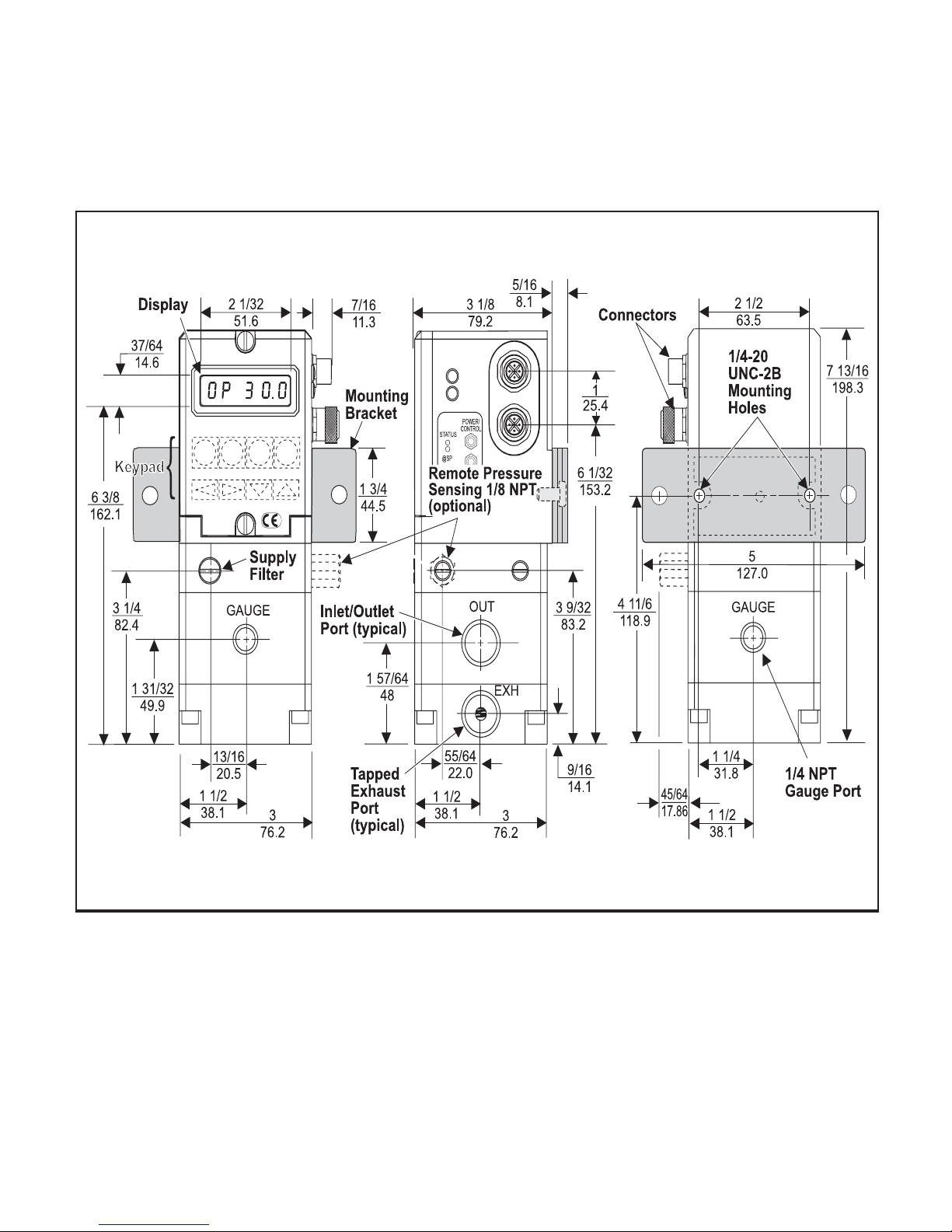
Figure 1. T7900 Outline Dimensions shown with Mounting Kit 19634-1.
INSTALLATION
The Model T7900 is supplied with a Mounting Kit 19634-1
for Panel or Wall Mounting. For more information, see
Figure 1. above.
If the Remote Pressure Sensing Option has been
provided, connect an air line from the Remote Pressure
Sensing Port to the sensing location. Support the 1/8
NPT remote pressure sensing adapter with a wrench
when installing the air line fitting. For more information,
see Figure 1. above.
(Included with Unit)
LEGAL NOTICE:
The information set forth in the foregoing Installation, Operation and Maintenance Instructions shall
not be modified or amended in any respect without
prior written consent of Fairchild Industrial Products Company. In addition, the information set
forth herein shall be furnished with each product
sold incorporating Fairchild's unit as a component
thereof.
1
Page 2
Pneumatic Connections
Electric Connection
Clean all pipelines to remove dirt and scale before
installation.
Apply a minimum amount of pipe compound to the male
threads of the air line only. Do Not use teflon tape as a
sealant. Start with the third thread back and work away
from the end of the pipeline to avoid the possibility of getting
pipe compound into the air lines.
The inlet and outlet ports are labeled on the side of the
transducer. Tighten connections securely. Avoid undersized fittings that will limit the flow through the transducer.
For more information, see Figure 1. “T7900 Outline Dimensions” on page 1.
NOTES:
Oil free air is required. Use a filter to remove
dirt and liquid in the air line ahead of the
transducer. If an air line lubricator is used, it
MUST be located downstream to avoid interference with transducer performance.
Supply pressure must be no less than 5 psig,
[0.35 BAR], (35 kPa), above maximum output.
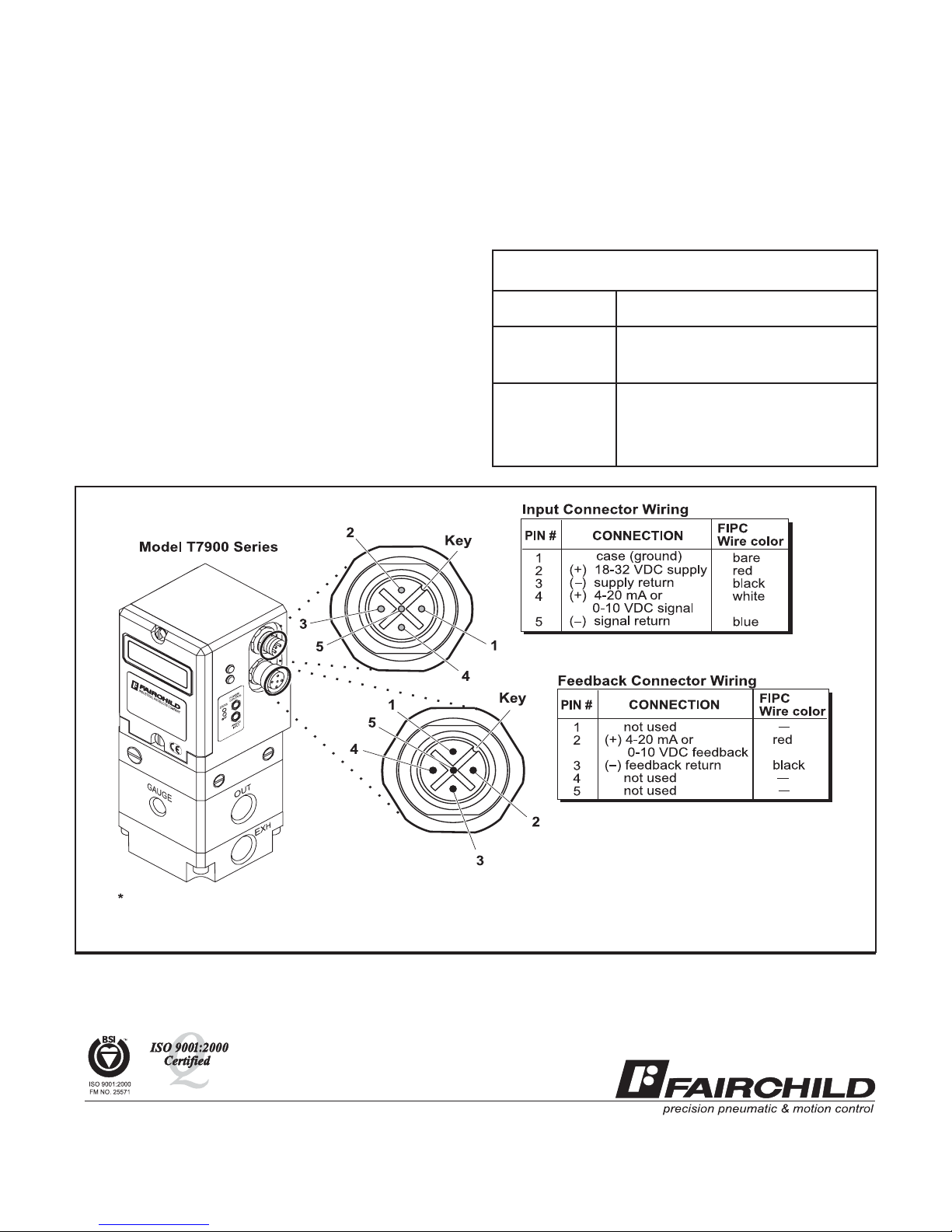
For the T7900 Transducer, make connections as shown
below in Figure 2. “Electrical Connections”. For compatible
cord sets and connectors refer to Table 1. below.
For signal lines of six feet or less, 22 gage wire may be used.
For longer signal lines, use 18 gage wire. Shielded cable
Must Be Used for the signal lines for noise immunity.
Table 1. T7900 Cables and Connectors (Sold Separately)
Part number
055-IPI-089M
055-IPI-089-F
032-IPI-009-3M
Description
Male connector (Feedback)
Female connector (Input)
Male cable w/one connector
(3 meter)
032-IPI-099-3F
Female cable w/one connector
(3 meter)
1
1
Colors apply only to FIPC DeviceNet compatible cables.
1
Figure 2. Electrical Connections.
II-500T7900
Litho in USA
Rev. C 9/02
Page 3

P.S.I. Supplies Pty Ltd trading as
PSI Fluid Power
For sales information contact:
www.psifluidpower.com.au
sales@psifluidpower.com.au
Ph: +61 (0) 3 9720 5577
 Loading...