

Fairchild T5220, T5220 Series, TXPD5220 Installation, Operation And Maintenance Instructions
Page 1
FAIRCHILD T5220 SERIES
ELECTRO-PNEUMATIC TRANSDUCER
Installation, Operation and Maintenance Instructions
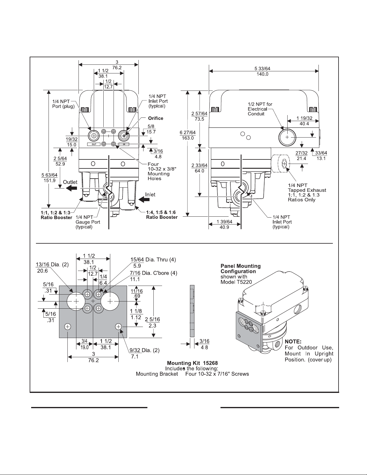
Figure 1. Model T5220 Outline Dimensions
Figure 2. Mounting Kit 15268. (Sold Separately)
INST ALLATION
The Model T5220 can be mounted directly onto a flat surface
using the two 10-32 tapped mounting holes in the base of the
housing. For more information, see Figure 1. “T5220 Outline
Dimensions” above.
The Model T5220 can be Panel Mounted using the
mounting bracket supplied in Mounting Kit 15268. For
more information, see Figure 2. above.
1
Page 2
Installation (Continued)
NOTE:
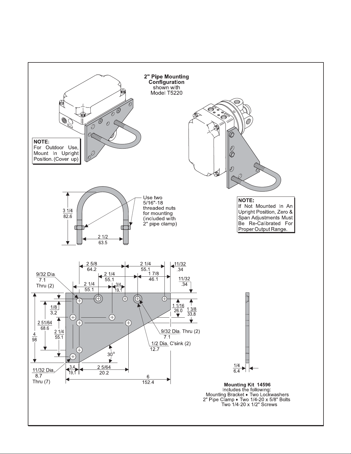
The Model T5420 can be mounted on a 2" pipe using the
Optional Mounting Kit 14596. For more information, see
Figure 3. below.
For outdoor use, mount the T5220 in an upright
position. This will help prevent rain water from
entering into the unit. For more information, see
Figure 3. “Mounting Kit 14596” below.
Figure 3. Optional Mounting Kit 14596. (Sold Separately)
2
Page 3
INSTALLATION
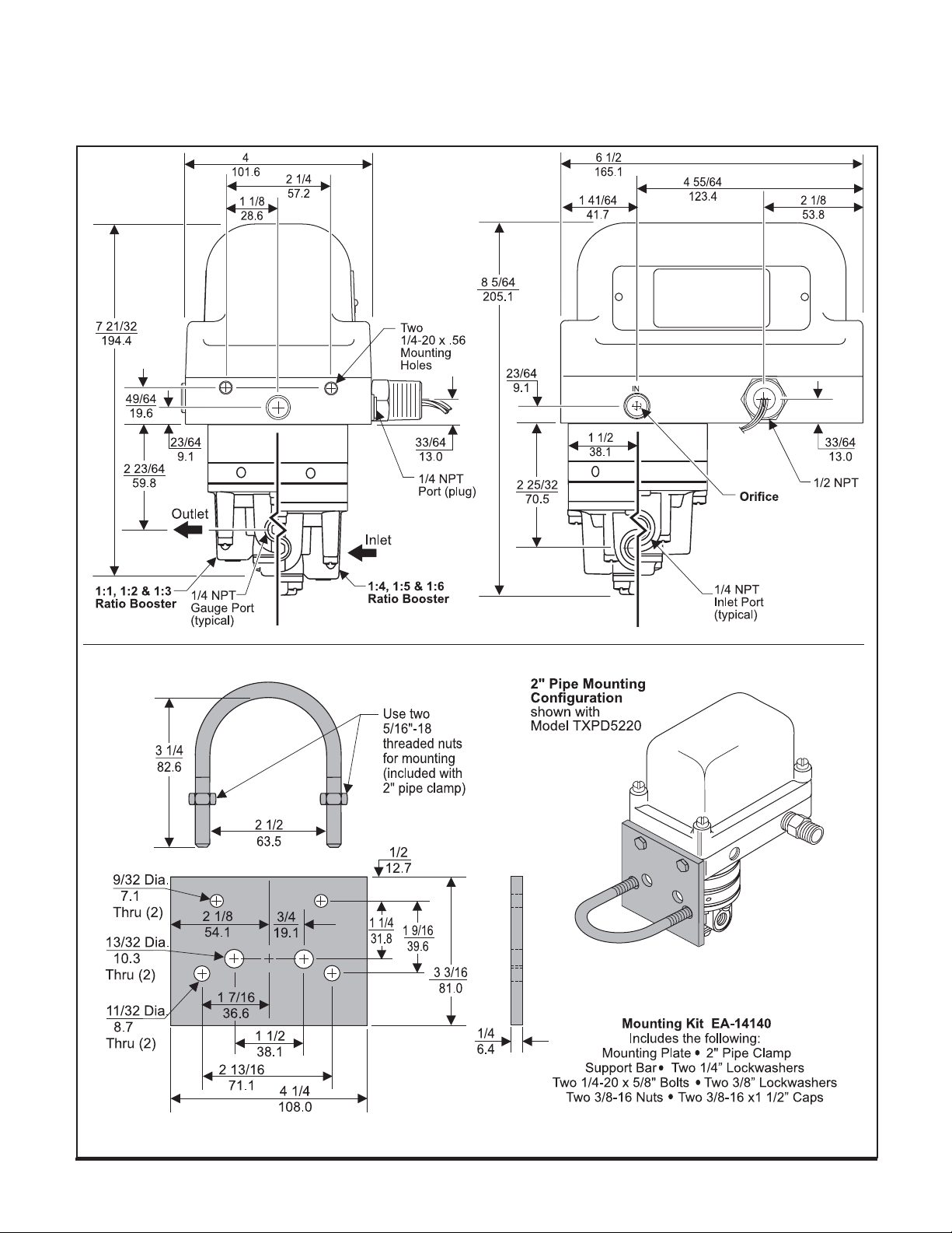
The Model TXPD5220 can be mounted directly onto a flat
surface using the four 1/4-20 x 7/16 tapped mounting holes
in the base of the housing . For more information, see Figure
4. “TXPD5220 Outline Dimensions” below.
14140 is available for Panel or 2" Pipe Mounting. For
more information, see Figure 5 below.
Mounting Kit
Figure 4. TXPD5220 Outline Dimensions.
Figure 5. Mounting Kit 14140. (Sold Separately)
3
Page 4

Pneumatic Connections
Electric Connection
Clean all pipelines to remove dirt and scale before installation.
Apply a minimum amount of pipe compound to the male
threads of the fitting only. Do Not use teflon tape as a
sealant. Start with the third thread back and work away
from the end of the fitting to avoid the possibility of
contaminating the transducer. Install the transducer in the
air line.
NOTES:
Instrument quality air, per ISA Standards
D7.3-1981, is required. Use a filter to remove dirt and liquid in the air line ahead of
the transducer for correct performance. If
an air line lubricator is used, it MUST be
located downstream, beyond the transducer.
The user is responsible for insuring that the
environment in which the unit will be
installed, and the operating gas, are compatible with the materials in the trans-
WARNING:
To prevent possible ignition of hazardous
atmosphere, DO NOT REMOVE COVER from
the TXPD5220 Transducer while current is
on.
To maintain Explosion-Proof capability, DO
NOT DAMAGE mating surfaces between
cover and base. NEVER ADD GASKETS.
For the T5220 Transducer, make connections to the Terminal Block through a 1/2 NPT Conduit Connector (not
supplied) and a plastic sleeve as shown below in Figure 7.
“Electrical Connections”.
For the TXPD5220 Transducer, make connections from the
Sealed Connector Wires to an external Terminal Block. The
TXPD5220 Transducer has an additional ground wire that is
used. For more information, see Figure 7. “Electrical
Connections” below.
NOTE: The T5220 & TXPD5220 should be wired in
accordance with the wiring diagram inside of
cover.
Wiring in Hazardous Areas
Wiring in hazardous areas should be performed in accordance with the Table 1. and any local codes that apply.
Table 1. Hazardous Location Wiring Practices.
Country
U.S.
Canada
Agency
FM
CSA
Code
ANSI/ISA RP 12.6 & ANSI/NFPA 70
CEC Part 1
Intrinsically Safe Connections
Refer to the latest revision of the indicated drawing.
Table 2. Intrinsically Safe Installation Drawings.
Underwriting Group Drawing Number
FM (Factory Mutual)
CSA (Canadian Standards)
EC-14007
EC-16097
Figure 6. Electrical Connections.
4
Page 5

CALIBRATIONS / ADJUSTMENTS
Equipment Required for Calibration:
• Pneumatic Supply capable of delivering up to 150 psig.
• Current Supply capable of delivering up to 50 mA.
• Voltage Supply capable of delivering up to 10 VDC.
• Pressure Gage capable of a digital readout up to 50 psig
with an accuracy of .1%.
• Digital Volt Meter capable of a readout up to 30 mA or
10 VDC with an accuracy of .02%.
The following adjustments are provided:
Full Range Operation
Forward/Reverse Mode
Calibration - Zero and Span
FULL RANGE OPERATION
Forward Acting Mode Adjustment
NOTE:
1.
• Forward Acting Calibration-Zero
Air Supply must be on before adjustments are
made.
Connect the input signal to the transducer as shown
in Figure 6. “Electrical Connections.”
2.
Apply the minimum input signal and adjust the Zero
screw for minimum output pressure. Turn screw
counterclockwise to increase pressure and clockwise to decrease pressure.
• Forward Acting Calibration-Span
3.
Apply the maximum input signal and adjust the Span
screw on the potentiometer for maximum output
pressure. Turn screw clockwise to increase pressure and counterclockwise to decrease pressure.
Repeat steps 2-3 until the desired output range is
4.
obtained. For more information, see Figure 7. “T5220/
TXPD5220 Calibration Configuration.”
Reverse Acting Mode Adjustment
NOTE:
5.
• Reverse Acting Calibration-Zero
• Reverse Acting Calibration-Span
Intrinsically safe units cannot be set for reverse acting mode in field.
Connect the input signal to the transducer as shown
in Figure 6. “Electrical Connections.”
6.
Apply the minimum input signal and adjust the Zero
screw for maximum output pressure. Turn screw
counterclockwise to increase pressure and clockwise to decrease pressure.
7.
Apply the maximum input signal and adjust the Span
screw on the potentiometer for minimum output pressure. Turn screw counterclockwise to increase pressure and clockwise to decrease pressure.
Repeat steps 6-7 until the desired output range is
8.
obtained. For more information, see Figure 8. “T5200/
TXPD5200 Calibration Configuration.”
Figure 7. T5220 / TXPD5220 Calibration Configuration.
5
Page 6

MAINTENANCE
To clean the Orifice, use the following procedure:
Turn off the air supply to the transducer. If the
1.
transducer is a common supply unit, remove the Pipe
Plug from the In Port located on the rectangular base.
If the transducer is a separate supply unit, remove the
Air Line Fitting from the In Port.
2.
Remove the Orifice Assembly (9) from the unit by
threading a 1/4-20" Screw into the orifice housing and
pulling it out through the inlet port. For more informa-
tion, see Figure 8. “Exploded Drawing” below.
Clean with alcohol and dry with compressed air.
3.
NOTE:
To clean the Inner Valve Assembly, use the following
procedure:
1.
2.
3.
4.
NOTE:
Parts must be completely dry before reassembling.
Shut off the valve that is supplying air to transducer. It
is not necessary to remove the Transducer from air
line.
Remove Screws (7) holding the Retainer Cap (6) and
Plate (5) to Booster (1).
Pull out Inner Valve Assembly (4) and wash the seat
carefully.
Wipe off any particles that may be attached to rubber
Seat Ring Assembly (2). For more information, see
Detail A, below.
Avoid such solvents as acetone, carbon tetrachloride and trichlorethylene.
To clear probblems caused by Magnet malfunction,
use the following procedure:
1.
Shut off the valve that is supplying air to transducer. It
is not necessary to remove the Transducer from air
line.
2.
Remove three Screws (12) holding Magnet (11) to
Transducer (8).
3. Remove Magnet (11) and clean gap of any foreign
material with masking tape. For more information, see
View B, below.
4.
Place Magnet (11) over Coil (10) and tighten with three
Screws (12).
5.
Using a non-matalic rod, Raise up on the arm to make
sure Coil (10) is not sticking in Magnet (11).
NOTE:
To replace PC Board, use the following procedure:
1.
2.
3.
4.
If Coil is sticking, loosen Screws and reposition Magnet. Tighten Screws and repeat
step 5.
Disconnect wires from Terminal Block on PC Board (14).
Unsolder Red (+) and Black (-) Leads on PC Board (14).
Remove four Screws (13) holding PC Board (14) to
Transducer (8). For more information, see Figure 8.
“Exploded Drawing” below.
Replace PC Board (14) with the appropriate PC Board
from Table 3. on page 7.
Figure 8. Exploded Drawing.
6
Page 7

Maintenance (continued)
TROUBLE-SHOOTING
Table 3. T5220 Series Components.
Item
Qty.
1
2
3
4
5
6
7
8
9
10
11
12
13
14
14
14
14
14
14
14
14
1
2
1
1
1
1
1
1
2
1
1
4
1
1
1
1
1
1
1
1
3
1
1
For T5220, TFI5220, TFN5220, TFNI5220, TXPD5220,
& TXPDI5220 Units Only.
For TCI5220 Only.
Part No.
NS
NS
NS
NS
NS
NS
NS
NS
NS
NS
NS
NS
NS
13744-2
15638-2
13745-2
15483-2
14639-2
15640-2
13746-2
15639-2
Description
Transducer
Orifice
Coil
Magnet
Screw
Screw
Booster
Seat Ring Assembly
Screen
Inner Valve Assembly
Retainer Plate
Retainer Cap
Screw
1
1-5 mA PC Board
2
1-5 mA PC Board
1
4-20,10-50 mA PC Board
2
4-20,10-50 mA PC Board
1
1-5 VDC PC Board
2
1-5 VDC PC Board
1
1-9 VDC PC Board
2
1-9 VDC PC Board
NS: (Not Serviceable) In the Part No. column, NS indicates that the part is not available for field replacement.
Table 4. Trouble-Shooting.
Problem
No Output
Solution (check)
Supply Pressure
Clogged Orifice
Power Supply
Leakage
Low or Improper
Span Adjust
Pneumatic Connections
Zero and SpanAdjust
Supply Pressure Low
Output Leakage
Erratic Operation
DC Signal
Loose Wires or Connections
Liquid in Air Supply
Dirt in Magnet Gap
Unit Does Not
Replace PC Board
Operate
NOTE: Booster Repair Kits are available for the T5220.
Ratio
1:1
1:2
1:3
1:4
1:5
1:6
Kit Number
15288-1
15288-2
15288-3
15656-4
15656-5
15656-6
7
Page 8

IS-500T5220
Litho in USA
Rev. M 06/07
 Loading...