

查询SS24供应商
Features
• Glass passivated junctions.
• High current capability, low V
• For use in low voltage, high
frequency inverters free
wheeling, and polarity
protection applications.
SS22-S210
SS22 - S210
.
F
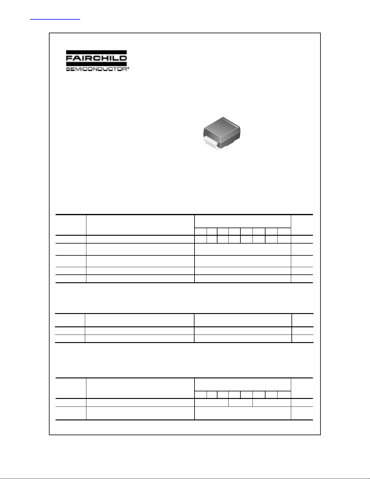
SMB/DO-214AA
COLOR BAND DENOTES CATHODE
Schottky Rectifiers
Absolute Maximum Ratings* T
Symbol
V
Maximum Repetitive Reverse Voltage 20 30 40 50 60 80 90 100 V
RRM
I
Average Rectified Forward Current
F(AV)
.375 " lead length @ T
I
Non-repetitive Peak Forward Surge Current
T
FSM
stg
8.3 ms Single Half-Sine-Wave
Storage Temperature Range -65 to +150
TJ Operating Junction Temperature -65 to +125
*These ratings are limiting values above which the serviceability of any semiconductor device may be impaired.
Parameter
= 75°C
A
Thermal Characteristics
Symbol
PD Power Dissipation 1.3 W
R
JA
θ
Thermal Resistance, Junction to Ambient * 75
*Device mounted on FR-4 PCB 0.013 mm.
Parameter
= 25°C unless otherwise noted
A
22 23 24 25 26 28 29 210
Value
Units
2.0 A
50 A
C
°
C
°
Value
Units
C/W
°
Electrical Characteristics T
Symbol
Parameter
= 25°C unless otherwise noted
A
Device
22 23 24 25 26 28 29 210
VF Forward Voltage @ 2.0 A 500 700 850 mV
IR
Reverse Current @ rated V
R TA
TA
= 25°C
= 100°C
0.4
10
2001 Fairchild Semiconductor Corporation
Units
mA
mA
SS22-S210, Rev. C
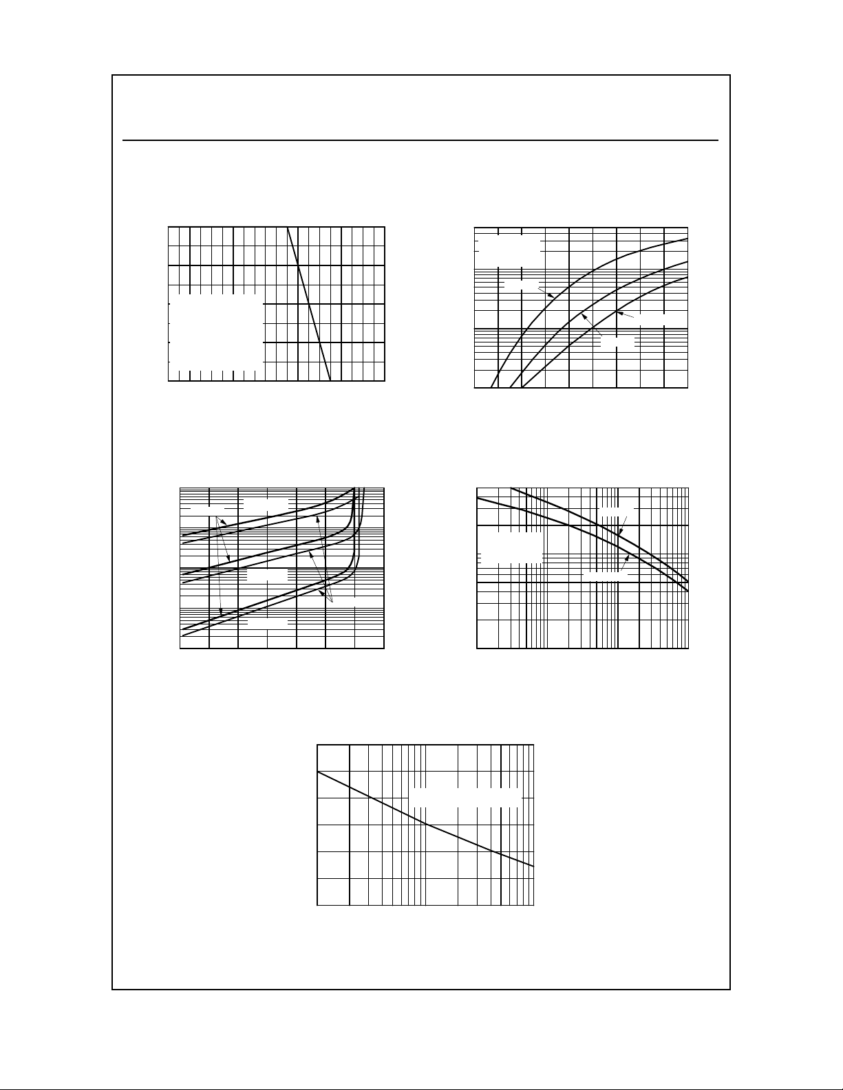
T ypical Characteristics
SS22-S210
Schottky Rectifiers
(continued)
2
[A]
F
1.5
SINGLE PHASE
1
HALF WAVE
60Hz
RESISTIVE OR
INDUCTIVE LOAD
0.5
P.C.B. M O UN T ED
ON 8.0x8.0m m
COPPER PAD AREAS
Average Rectified Forward Current, I
0
50 60 70 80 90 100 110 120 130 140 150
Lead Temperature [ºC]
Figure 1. Forward Current Derating Curve
10
º
T = 100 C
SS22-24
1
[mA]
R
0.1
0.01
Reverse Current, I
0.001
0 20406080100120140
A
º
T = 75 C
A
º
T = 25 C
A
SS25-S210
Reverse Voltage, VR[V]
Figure 3. Reverse Current vs Reverse Voltage
50
º
T = 25 C
A
f = 1.0 MHz
20
Vsig = 50mVp-p
10
[A]
F
5
1
SS22-24
SS28 - S210
SS25-26
Forward Current, I
0.1
0.2 0.3 0.4 0.5 0.6 0.7 0.8 0.9 1 1.1
Forward Voltage, VF [V]
Figure 2. Forward Voltage Characteristics
500
SS22-24
200
[pF]
T
100
50
20
Total Capacitance, C
10
º
T = 25 C
A
f = 1.0 MHz
Vsig = 50mVp-p
SS25-S210
0.1 0.5 1 5 10 20 50 100
Reverse Voltage, VR [V]
Figure 4. Total Capacitance
60
[A]
FSM
50
40
8.3ms Single Half Sine- Wave
JEDEC Method
30
20
10
Peak Forward Surge Current, I
0
12 51020 50100
Number of Cycles at 60Hz
Figure 5. Non-Repetitive Surge Current
SS22-S210, Rev. C

TRADEMARKS
The following are registered and unregistered trademarks Fairchild Semiconductor owns or is authorized to use and is
not intended to be an exhaustive list of all such trademarks.
ACEx™
Bottomless™
CoolFET™
CROSSVOLT™
DenseTrench™
DOME™
EcoSPARK™
E2CMOS
EnSigna
TM
TM
FACT™
FACT Quiet Series™
STAR*POWER is used under license
FAST
FASTr™
FRFET™
GlobalOptoisolator™
GTO™
HiSeC™
ISOPLANAR™
LittleFET™
MicroFET™
MicroPak™
MICROWIRE™
OPTOLOGIC™
OPTOPLANAR™
PACMAN™
POP™
Power247™
PowerTrench
QFET™
QS™
QT Optoelectronics™
Quiet Series™
SILENT SWITCHER
SMART START™
STAR*POWER™
Stealth™
SuperSOT™-3
SuperSOT™-6
SuperSOT™-8
SyncFET™
TinyLogic™
TruTranslation™
UHC™
UltraFET
VCX™
DISCLAIMER
FAIRCHILD SEMICONDUCTOR RESERVES THE RIGHT TO MAKE CHANGES WITHOUT FURTHER
NOTICE TO ANY PRODUCTS HEREIN TO IMPROVE RELIABILITY, FUNCTION OR DESIGN. FAIRCHILD
DOES NOT ASSUME ANY LIABILITY ARISING OUT OF THE APPLICATION OR USE OF ANY PRODUCT
OR CIRCUIT DESCRIBED HEREIN; NEITHER DOES IT CONVEY ANY LICENSE UNDER ITS PATENT
RIGHTS, NOR THE RIGHTS OF OTHERS.
LIFE SUPPORT POLICY
FAIRCHILD’S PRODUCTS ARE NOT AUTHORIZED FOR USE AS CRITICAL COMPONENTS IN LIFE SUPPORT
DEVICES OR SYSTEMS WITHOUT THE EXPRESS WRITTEN APPROVAL OF FAIRCHILD SEMICONDUCTOR CORPORATION.
As used herein:
1. Life support devices or systems are devices or
systems which, (a) are intended for surgical implant into
the body, or (b) support or sustain life, or (c) whose
failure to perform when properly used in accordance
with instructions for use provided in the labeling, can be
reasonably expected to result in significant injury to the
user.
PRODUCT STATUS DEFINITIONS
Definition of Terms
Datasheet Identification Product Status Definition
Advance Information
Preliminary
No Identification Needed
Formative or
In Design
First Production
Full Production
2. A critical component is any component of a life
support device or system whose failure to perform can
be reasonably expected to cause the failure of the life
support device or system, or to affect its safety or
effectiveness.
This datasheet contains the design specifications for
product development. Specifications may change in
any manner without notice.
This datasheet contains preliminary data, and
supplementary data will be published at a later date.
Fairchild Semiconductor reserves the right to make
changes at any time without notice in order to improve
design.
This datasheet contains final specifications. Fairchild
Semiconductor reserves the right to make changes at
any time without notice in order to improve design.
Obsolete
Not In Production
This datasheet contains specifications on a product
that has been discontinued by Fairchild semiconductor.
The datasheet is printed for reference information only.
Rev. H4
 Loading...