

Page 1
www.SteamPoweredRadio.Com
FAIRCHILD
DOUBLE
AMPLIFIER
CARDS
---
MODEL
692AD
-
692AD/TXI
INTEGRA
II
SERIES
1B692AD/268
INSTRUCTION MANUAL
-
AIRCHILD
SOUND
EQUIPMENT
CORPORATION
,
10-40 45th Avenue, Long Island City, N.Y. 11101 , 212 784-6163
Page 2

www.SteamPoweredRadio.Com
Page 3
www.SteamPoweredRadio.Com
FAiiiCiiILD
MODEL
692AD
AHFLIFIZR
CARD
DV
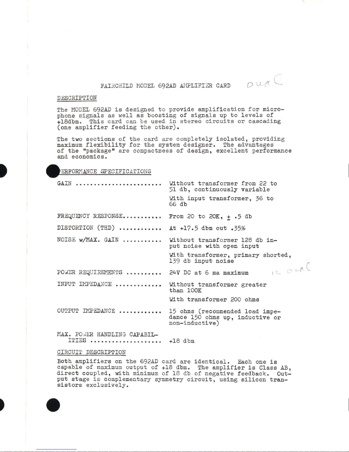
DESCRIPTION
The
MODEL
692AD
is
designed
to
provide
amplification
for
micro-
phone
signals
as
well
as
boosting
of
signals
up
to
levels
of
+18dbm.
This
card
can
be
used
in
stereo
circuits
or
cascading
(one
amplifier
feeding
the
other).
The two
sections
of
the
card
are
completely
isolated,
providing
maximum
flexibility
for
the
system
designer.
The
advantages
of
the
"package"
are
compactness
of
design,
excellent
performance
and
economics.
-
ERFORMANCE
SPECIFICATIONS
GAIN•··•••·••·••·••·•••••··•
Without
transformer
from
22
to
51
db,
continuously
variable
With
input
transformer,
36
to
66
db
FREQUENCY
RESPONSE
•.•••••••••
From 20
to
20K, ±
.5
db
DISTORTION
(THD)
••••••••••••
At
+17.5
dbm
out
.35%
NOISE
w/tlAX.
GAIN
.•..•••••••
POwER
REQUIREMENTS••••••••••
Without
transformer
128
db
in-
put
noise
with
open
input
With
transformer,
primary
shorted,
139 db
input
noise
24V
DC
at 6 ma
maximum
I L
1-"'
INPUT
Il'iPEDANCE
•••••••••••••
Without
transformer
greater
than
100K
With
transformer
200 ohms
OUTPUT
IMPED.ANGE··••••••··••
15
ohms (recommended
load
impe-
dance
150 ohms
up,
inductive
or
non-inductive)
tlA.X.
PO./ER
HANDLING
CAPABIL-
ITIES
• • • • • • • • • • • • • • • • • • • • +18 d
bm
CIRCUIT
DESCRIPTION
Both
amplifiers
on
the
692AD
card
are
identical.
Each one
is
capable
of
maximum
output
of
+18 dbm. The
amplifier
is
Class
AB,
direct
coupled,
with
minimum
of
18
db
of
negative
feedback.
Out-
put
stage
is
complementary
symmetry
circuit,
using
silicon
tran-
sistors
exclusively.
-
Page 4

www.SteamPoweredRadio.Com
+ 24VDC
i
IN96
100
Z(22)
◄
I
~
,/'I',/'
'
DI
R5
I
69
2 A D
I
I
'
I
!
i
BLUE
I
Tl
I
'
IN
HI
X
(20)
tP
RED
BEYER
I
I
TRl45/BV
I
35570
I
I
W(l9)
I
BLK
I
IN
LO
YELLOW
P{l3)
AMP
G
ND
'
I
I
-
I
+ 24VDC
I
D2
R7
L(IO)
◄
I
►
I
.,/1/\/'
IN96
100
-
I
I
s92...:o
I
BLUE
i
T2
IN
HI
J(8)~
BEYER
~II~
i"
TRl45/BV
ru
:2
35570
~
~
H(7)~
IN
LO
L__
YELLOW
8(2)
AMP
GND
NOTE
:
I.
UNLESS
OTHERWISE
SPECIFIED
ALL
RESISTORS
ARE
IN
OHMS,
1/4
W.
ALL
CAPACITORS
ARE
IN
MFD
.
* RESISTOR
VALUE
TO
BE
SELECTED
.
l l
T~om
220K
r
I
C
~
06
I
2N4010
I
,~t
I
l l
+lc
,o
{RIB
220K
1100/25
692AD
AMP SCHEMATIC
l
ei
1Rl5
750PF
Q
?w'
~
%
05
2N4010
'-'
---,
..,
t,,.
•
R20
-NV'
470
2.2K
IOOK
-
I
l•"
8.2K
. *G-130
07
2
N4010
RB
100
ISSUE : I
10-24-067
2-
THE
VALUE OF
Rl,R2
,
R3 8 R4
WAS
3011.
ADDED
NOTE.
2N36431
2
N36
38
I
lc11
T
300/3
,,,.J
\.'
"'-..
J
OUT
r,,,
C5
+Tioo
115
+__Lc6
000/15
OUT
r.,
C7
+Tioo,
,5
+I
CB
100/15
Rl2 ....L.Cl2
'J
s;:,
470
T
30013
Rl4
R24
2.2K
IOOK
B-96284
Page 5

www.SteamPoweredRadio.Com
Each
amplifier
is
decoupled
from the power supp
ly
f or minimum
interaction.
The power
supply feeding the
amplifier
card
should
have
ripple
not
higher
than
.5
mv
rms
for
best
S/N
ratio.
Gain
of
the
amplifier
is
controlled
by means
of a potentiometer
connected
i n
the
feedback
loop,
thereby
reducing
the
distortion
of
the
amplifier
as
the gain
is
decreased.
A
total
of
29
db
of
gain control
is
accomplished
in
this
manner.
Input
transformers
are
well
shielded
and
capable
of
accepting
levels
as
high
as O dbm
without
overloading.
Transformers
are
mounted
directly
on the
card
for
minim
um
noi
se
pickup
and
minimum
high
frequency
loss.
INSTALLATION
The
692AD
card
can
be
used
in
conjunction
with
the
692
series
remote
control
equipments
in
the
692RI1
rack
mount,
or
it
can
be
A
mounted
separately
using the
692SCH
single
card
holder
(which
W,
comes
complete
with
card
connector).
Connections
are
made
as
follows:
PIN 2 -
Negative
(-24V)
amplifier ground
LO
side
input
4 -
Output
7 -
Input
-
LO
8 -
Input
- HI
10
- +24 V
13 -Negative
(-24V)
second
amplifier ground
LO
side
15 -Output
(second
amplifier)
19 -Input
-
LO
(second
amplifier)
20 -
Input
- HI
(second
amplifier)
22 - +24V
(second
8.lilplifier)
Printed
circuit
board
has
provision
for
the
two
amplifiers
to
be
connected
throu
~h a
single
power
connection.
If
desired,
however,
the
two am
plifiers
can
be
separated
if
they
are
to
be
fed
from
different
power
supplies
and
maximum
isolation
between
the
two
amplifiers
is
desired.
PRECAUTION
should
be
observed
in
locating
the
card
in
the
system.
\,lb.en
input
transformers
are
mount ed on
the
card,
the
692AD
should
be
mounted
as
far
as practical
from
any
strong
magnetic
field
source.
Regardless
of
the
shielding
of
the
input
transformers,
there
is a possibility
of
hum
pickup
affectin
g
the
overall
performance
of
the
amplifier
in
the
system.
A
'l'TACHl"IEN
TS -Schematic
dia
gram
692AD
- B96284
Dimension
Drawing
692AD
WAR.JUNTY & SERVICE
POLICY
See
standard
warranty
policy
attached
to
and
forming
part
of
this
manual.
To
validate
warranty,
complete
and
return
th
e
-
Page 6

www.SteamPoweredRadio.Com
warranty
registration
card
provided.
If
there
is
any
question
on
this,
or
any
other
FAIR
CHILD
professional
product,
please
contact
the
factory:
FAIRCHILD
SOUND
EQUIPMENT
CORPORATION,
10-4-0
45th
Avenue,
Long
Island
City,
New
York
11101.
When
returning
any
FAIRCHILD
professional -~roduct
to
the
factory
for
any
reason,
include
a
brief
statement
with
the
unit
indicating
the
reason
for
the
return.
-
-
Page 7

www.SteamPoweredRadio.Com
-
-
 Loading...