

Page 1
FAIRCHILD MODEL HPD
High Pressure Regulator
Installation, Operation and Maintenance Instructions
Introduction
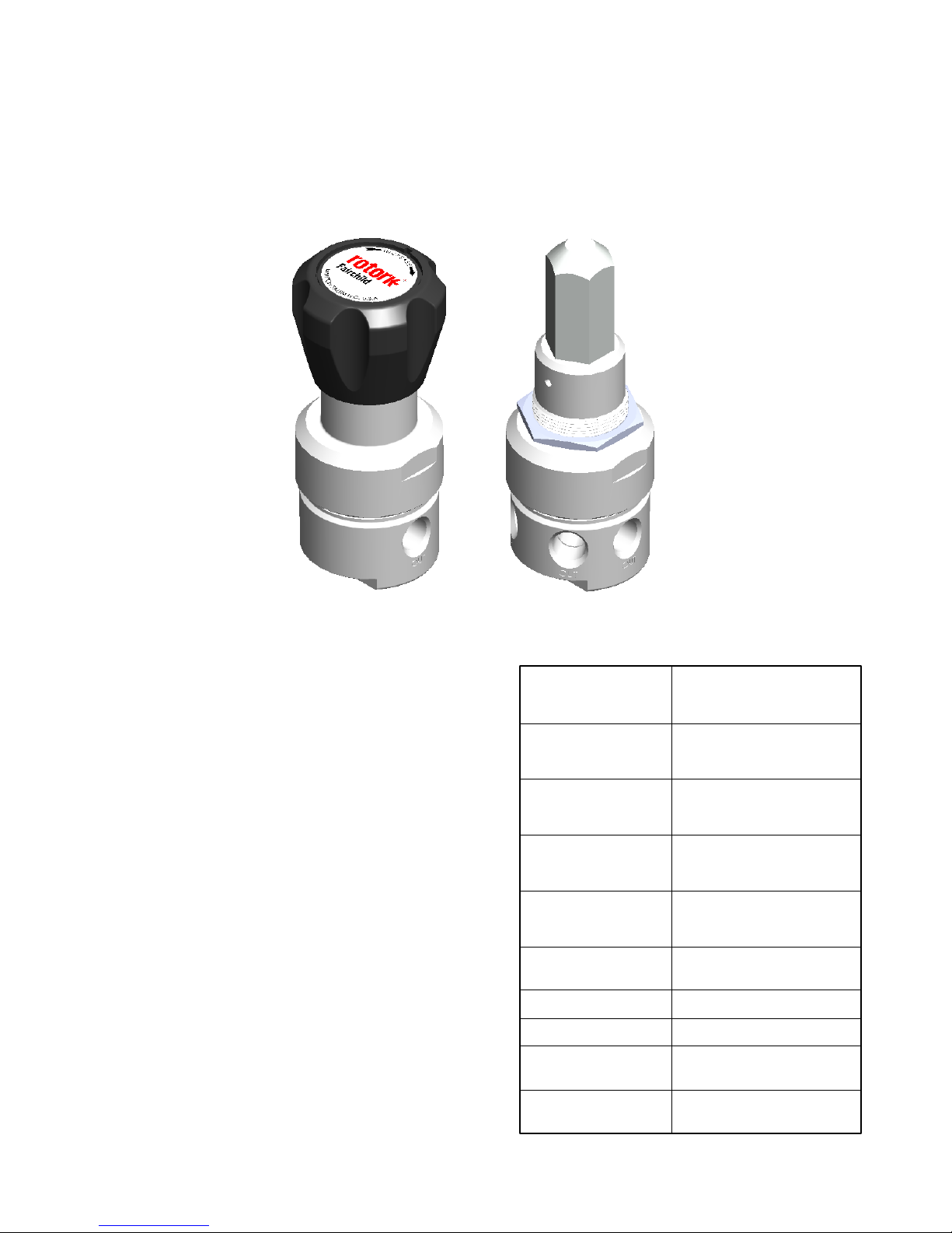
The Fairchild HPD series pressure regulator is
a precision engineered, diaphragm sensing,
pressure reducing regulator designed to
regulate pressure of speciality gases and
liquids. This single stage,low to medium flow
capacity pressure regulator will fullfil pressure
control requirements in analytical, medical and
laboratory instrumentation. The 316 stainless
steel construction and engineered polymer
seals permit the use of both corrossive and non
corrosive media.
Features
Three polymer seat materials provide
•
media compatility and supply pressure
capability up to 6,000 psig.
Inconel diaphragm for corrosion
•
resistance and long life.
Five outlet pressrue ranges provide
•
optimum sensitivity
20 micron inlet filter
•
0.06 Cv flow coefficient
•
Relieving and non relieving designs
•
Tamperproof adjustment option
•
Table 1. Specifications & Limits
Maximum Supply
Pressure
(Seat Material)
3500 psig
CPTFE
PEEK
Vespel SP-1
Ambient
Temperature Limits
Supply Pressure
Effect
Connection Sizes
Connection Thread
Maximum Cv
Weight
240 Bar
24 MPa
6000 psig
410 Bar
41 MPa
6000 psig
410 Bar
41 MPa
-40º to +200ºF
-40º to +93ºC
< 2% of supply pressure
change
1/4" pipe
NPTF
Supply Valve 0.06
Exhaust Valve 0.02
2.21 lb
1.002kg
1
Page 2
FAIRCHILD MODEL HPD
Pressure Regulator
Installation, Operation and Maintenance Instructions
34.8
1.37
53.8
2.12
31.8
1.25
HPD1***A**K*N
1 Inlet & 1 Outlet Port
1/4 NPTF or BSPT
55.9
2.20
4.88
123.9
58.4
2.30
50.5
1.99
HPD1*2N******
2 x 10-32 UNF-2B X 0.36 dp
HPD1*2U******
2 x M5 x 1 X 0.36 dp
19.1
10.2
0.75
0.40
5.5
0.22
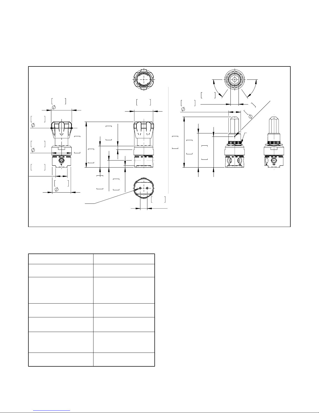
Figure 1.
50.8
2.00
Front
Model HPD Outline Dimensions
19.1
0.75
32.8
1.29
137
5.40
92.7
3.65
22.2
0.88
83.8
55°
Hex
3.2
Thread
1 3/8 -18
3.30
Front
HPD1***B**T*P
2 Inlet & 2 Outlet Ports
1/4 NPTF or BSPT
55°
Vent
0.13
Dimensions:
[mm]
inches
Table 2. Material of Construction
Valve Body & Bonnet
Supply & Exhaust Valves
Seats
Diaphragm
Seals
Springs
Supply Valve
Range Spring
External Finish
316 Stainless Steel
316 Stainless Steel
CPTFE
PEEK
Vespel SP-1
Inconel
PTFE
316 Stainless Steel
Music Wire
Passivated
Installation
You can mount the pressure regulator in any
position without affecting it's operation.
Clean all pipe fittings to remove contaminates
before installation.
Apply a minimum amount of pipe compound or
Teflon thread tape to the male threads of the fitting.
Start with the second thread back and work away
from the end of the fitting to avoid thread tape or
compound from contaminating the pressure
regulator.
The Inlet and Outlet are labeled "IN" and "OUT".
Tighten all connections securely. Avoid undersized
fittings that will limit the flow through the pressure
regulator
.
For more information, see Figure 1.
CAUTION
limit the supply pressure from the downstream
piping system. Employ properly sized pressure
limiting device to protect the piping system
downstream of the pressure regulator from the
effects of the supply pressure in the event of a
pressure regulator failure.
- Do not rely on the pressure regulator to
2
Page 3

FAIRCHILD MODEL HPD
Pressure Regulator
Installation, Operation and Maintenance Instructions
Panel Mounting
To panel mount the HPD, the knob must first be removed. To remove the knob, first using a small
screwdriver, pry up the insert in the top to expose the range screw and jam nut. Remove the jam nut and
then unscrew the knob from the range screw. Insert the HPD pressure regulator through the 1 3/8" hole in
the panel and fix it in place with the retaining nut. Reinstall the knob on the range screw and fix it in place
with the jam nut. Reinstall the knob cover
Knob adjustment
The knob on the HPD pressure regulator can be adjusted to limit the range of the output pressure. First
assure the pressure regulator has the intended operating supply pressure applied to the unit. Remove the
cover from the top of the knob and loosen the jam nut on the range screw. Insert a 3/16" hex wrench in the
range screw and adjust the pressure regulator to the desired maximum range. (Note, do not set the
pressure regulator to more than 110% of the rated range.) Adjust the knob so that it stops against the
bonnet. Tighten the jam nut to lock the knob to the range screw. Reinstall the knob cover.
Model
HPD
Analytical
Instrument
Process
Model
HPD
3 Way
Valve
Tank Change
Over System
Model
HPD
3
Page 4

MAINTENANCE
WARNING
Shutting off air supply to the pressure
regulator and adjacent equipment can create
dangerous system conditions.
To service the Model HPD, use the following steps:
Remove the Knob Cap and remove the Nut
1.
holding the Knob in place. Remove the Knob
from the Range Screw.
Remove the Bonnet from the Valve Body.
2.
Remove the Spring Seat, Range Spring and
3.
Diaphragm Assembly from the Valve Body.
Remove the Seat Retainer from the Valve Body.
4.
Remove the Valve , Valve Seat, Spring and
5.
Guide from the Valve Body.
Wash parts with instrument type cleaning
6.
solution, preferable in an ultrasonic cleaner.
Rinse and dry parts before reassembly.
Reassemble in reverse order.
7.
Torque Seat Retainer to 100 in.lb.
Torque Bonnet to 150 ft.lb.
Trouble Shooting
Problem
Leakage
High
Bleed
Source
Bonnet
• Relief Valve
• Supply Valve
• Supply Seat
• Diaphragm
Assembly
Solution
Tighten the Bonnet
• Clean all parts
including Valve
Body.
• If damaged, install
the service kit.
NOTE: If the standard maintenance procedure
does not correct the problem, install the
appropriate Service Kit per table below.
Service Kit Part No. 21916-
* * *
PSIG BAR
Pressure
Range
Seat
Material
Relief
0-25 0-1.7
0-50 0-3.5
1-100 0.07-7.0
2-250 0.15-17.0
PEEK
CTFE
Vespel SP-1
Non-Relieving
Relieving
3
4
5
7
P
T
V
N
R
Cap
Nut
Knob
Option
Bonnet
Range Screw
Spring Seat
Diaphragm
Assembly
Non-Relieving
Option
Spring
Diaphragm
Assembly
Relieving
Option
Seat
Retainer
Valve Seat
Valve
Spring
Guide
Snap
Ring
Spacer
2 Port
Valve Body
Filter
Option
LEGAL NOTICE:
The information set forth in the foregoing
Installation, Operation and Maintenance
Instructions shall not be modified or amended
in any respect without prior written consent of
Fairchild Industrial Products Company. In
addition, the information set forth herein shall
be furnished with each product sold incorporating Fairchild's unit as a component thereof.
Cap
Tamperproof
Option
Nut &
Bonnet
Panel
Mounting
Option
4 Port
Valve
Body
Option
FAIRCHILD INDUSTRIAL PRODUCTS CO.
REGISTERED TO ISO 9001:2008
10002346 QM08
Fairchild Products Company
3920 West Point Blvd. • Winston-Salem, NC 27103
phone: (336) 659-3400 • fax: (336) 659-9323
sales@fairchildproducts.com • www.fairchildproducts.com
IS-10000HPD
Litho in USA
Rev - 10/12
4
 Loading...