

Page 1

User Guide for
FEBFMT1030_MEMS01
Evaluation Board
Motion Tracking Module with MT Software
Suite
Featured Fairchild Products:
FEBFMT1030, FMT1030, FMT1020,
FMT1010
For technical support, please contact
Fairchild Semiconductor
or your local sales team
Fairchild Sales Offices
© 2015 Fairchild Semiconductor Corporation FEBFMT1030_MEMS01 • Rev. 1.0
Page 2

Table of Contents
1. Introduction ............................................................................................................................... 3
1.1. Description ....................................................................................................................... 3
1.2. Features ............................................................................................................................ 3
1.3. Ordering Information ....................................................................................................... 3
2. Photographs............................................................................................................................... 4
3. Getting Started .......................................................................................................................... 5
3.1. Installing MT Software Suite ........................................................................................... 5
3.2. Displaying Data in MT Manager ..................................................................................... 6
3.3. Configuring the FMT with MT Manager ......................................................................... 7
3.4. Other Functionality of MT Manager ................................................................................ 8
3.5. Embedded Examples ........................................................................................................ 8
3.6. Frames of Reference used in FMT ................................................................................... 8
4. Package and Handling............................................................................................................. 10
4.1. Evaluation Kit ................................................................................................................ 10
4.1. Pin Descriptions ............................................................................................................. 13
4.2. Schematics ...................................................................................................................... 14
4.3. Physical Dimensions ...................................................................................................... 16
4.4. Electrical Specifications ................................................................................................. 16
4.5. Absolute Maximum Ratings........................................................................................... 17
5. Revision History ..................................................................................................................... 18
© 2015 Fairchild Semiconductor Corporation 2 FEBFMT1030_MEMS01 • Rev. 1.0
Page 3
1. Introduction
Part Number
Description
Packing Method
FEBFMT1030_MEMS01
Evaluation Kit for FMT1030 AHRS
Single unit
This user guide describes the Evaluation Kit for the FMT1030. The FMT1030 Evaluation
Kit is designed to support the evaluation of the FMT1000-series, in particular the
FMT1030 Attitude and Heading Reference System.
1.1. Description
The FMT1000-series is a module outputting 3D orientation, 3D rate of turn, 3D
acceleration and 3D magnetic field. It is specifically designed for industrial applications
featuring vibration rejection, a robust sensor fusion algorithm and a high update rate. The
FMT1000-series can be configured for any application.
The FMT1000-series Evaluation Kit is an excellent tool to start working with the
FMT1000-series. It has a pre-mounted FMT1030 AHRS and comes with the extensive
MT Software Suite and USB-cabling. The MT Software Suite is full-featured, with
logging and visualization options, intuitive configuration windows and possibilities to
export data for use in other programs. The Software Development Kit contains source
code for communication and libraries for data processing.
The 24-pins header connects to all interfaces available on the FMT1000-series module.
Connections with development platforms for Cortex-M processors of different brands can
be made easy using the Fairchild examples on the mbed.org website.
Specifications of the FMT1000-series can be found in the FMT1000-series data sheet.
1.2. Features
1.3. Ordering Information
© 2015 Fairchild Semiconductor Corporation 3 FEBFMT1030_MEMS01 • Rev. 1.0
Figure 1. FEBFMT1030_MEMS01 Development Board
Easy to use Development Board
Complete MT Software Suite
o MT Manager Logging and Visualization GUI
Windows 7 and Linux
o SDK for Windows, Linux
o Source Code/Drivers (platform-independent)
o Magnetic Field Mapper
Drivers and Examples on ARM
®
mbedTM
Full Functionality
Delivered with FMT1030 Mounted
USB, RS232, UART, SPI, I
2
C Interfaces
Page 4
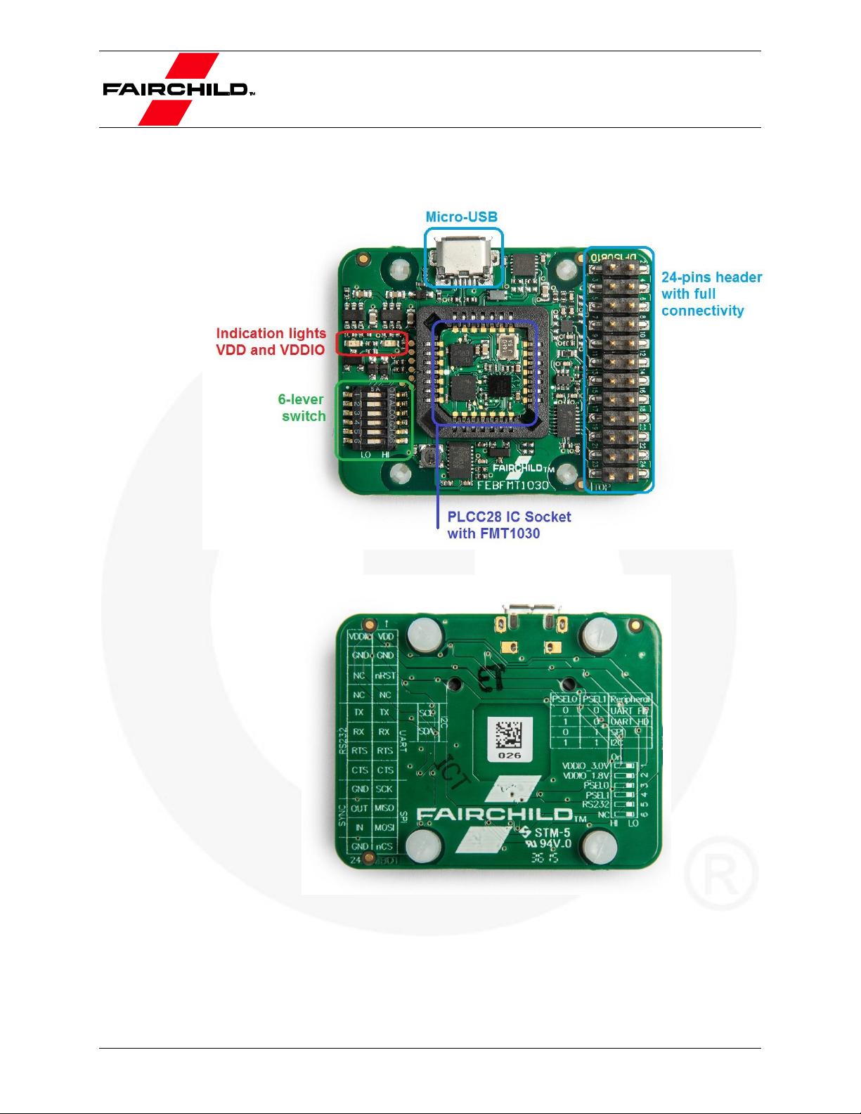
2. Photographs
Figure 2. Top View of the FMT1000-Series Evaluation Board with the Various Components
Figure 3. Bottom View of the FMT1000-Series Evaluation Board with the description of the
header and switch. Text is displayed as see-through.
© 2015 Fairchild Semiconductor Corporation 4 FEBFMT1030_MEMS01 • Rev. 1.0
Page 5
3. Getting Started
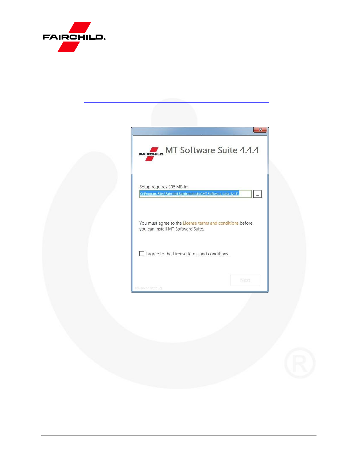
3.1. Installing MT Software Suite
The MT Software Suite is available on the Fairchild Motion Tracking website:
https://www.fairchildsemi.com/products/sensors/mems-motion-sensors/.
The installation procedure consists of a set of several installers and starts with this screen:
Figure 4. MT Software Suite Installer Home Screen
© 2015 Fairchild Semiconductor Corporation 5 FEBFMT1030_MEMS01 • Rev. 1.0
Page 6
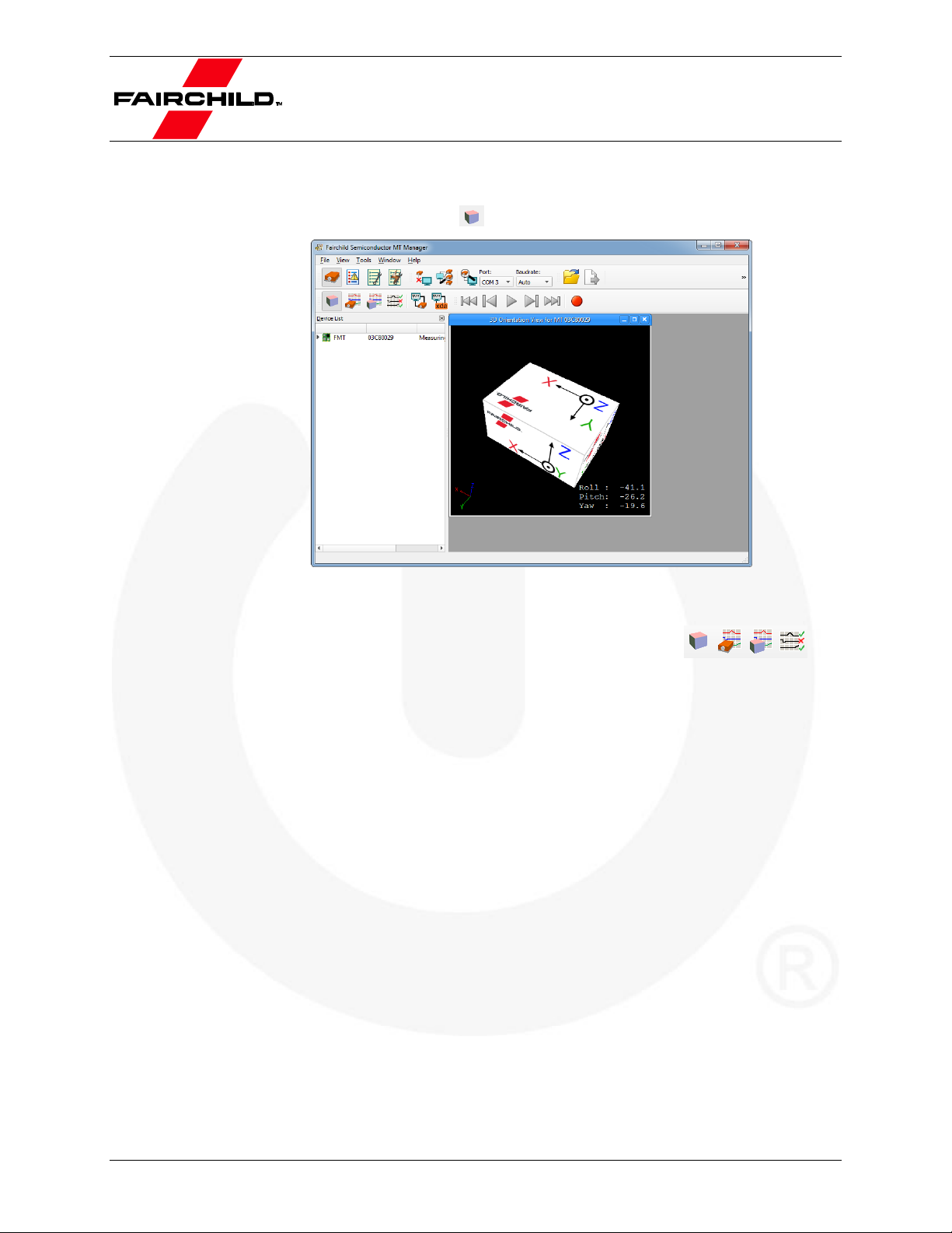
3.2. Displaying Data in MT Manager
When the FEBFMT1030 is connected (the FEBFMT1030 will automatically be
installed), click the 3D View icon: . This shows the 3D box representation of the FMT.
Figure 5. The 3D Box View of the MT Manager
The other visualizations can be opened using the windows toolbar: .
Refer to the MT Manager User Manual for more information on these graphs and their
features. The MT Manager User Manual can be found via Help – Documentation
© 2015 Fairchild Semiconductor Corporation 6 FEBFMT1030_MEMS01 • Rev. 1.0
Page 7

3.3. Configuring the FMT with MT Manager
MT Manager is an excellent tool to configure the FMT. Click the Output Configuration
button:
The following screen appears:
Figure 6. Output Configuration Window of a FEBFMT1030
By default, the output of the FMT is orientation only. Click “Inertial Data” (∆q/∆v or
Rate of Turn/Acceleration) and “Magnetic Field” to be able to show this data in MT
Manager.
© 2015 Fairchild Semiconductor Corporation 7 FEBFMT1030_MEMS01 • Rev. 1.0
Page 8

Data
Symbol
Reference Coordinate System
Acceleration
ax, ay, az
Sensor-fixed
Rate of turn
ωx, ωy, ω
z
Sensor-fixed
Magnetic Field
mx, my, mz
Sensor-fixed
Free Acceleration
a
Local Tangent Plane (LTP), default ENU
Velocity Increment
∆vx, ∆vy, ∆v
z
Local Tangent Plane (LTP), default ENU
Orientation Increment
∆q0, ∆q1, ∆q
2
, ∆q3
Local Tangent Plane (LTP), default ENU
Orientation
Euler Angles, Quaternions or
Rotation Matrix (DCM)
Local Tangent Plane (LTP), default ENU
3.4. Other Functionality of MT Manager
With the MT Manager, it is possible to record data and export that data for use in other
programs, configure synchronization options and to review the test and calibration report.
More information on the functions in MT Manager can be found in the MT Manager
User Manual.
3.5. Embedded Examples
The FMT is designed for easy integration in embedded systems. To aid in development
example code is provided for the ARM mbed platform. An example implementation of
the Xbus Low Level Communication Protocol is provided as generic C99 compliant
source code1, while an ARM mbed specific application demonstrates the use of the Xbus
library to communicate with a FEBFMT1030 Evaluation Board using UART, SPI or I2C
communications.
The example code has been tested with the following ARM mbed compatible boards:
ST Nucleo F302R8 – Cortex M4
FreeScale FRDM-KL46Z – Cortex M0+
NXP EA LPC 4088 – Cortex M4
The example code is available at http://www.mbed.org/teams/Fairchild-Semiconductor.
Documentation on how-to-use is provided on the description page and in the code. Note
that these examples are provided as is and are not supported by the Fairchild support
team. The examples are licensed under the Apache License version 2.0.
Several basic commands were used, it is easy to extend the program with commands
from the Low-Level Communication Protocol (LLCP). This protocol is documented in
detail in the MT Software Suite and in the Low-Level Communication Protocol
Documentation.
3.6. Frames of Reference used in FMT
The FMT uses a right-handed coordinate system as the basis of the sensor of frame.
The following data is outputted in corresponding reference coordinate systems:
Table 1. Reference frame in FMT
1
Xbus example code is not specific to ARM processors and should be compatible with other embedded
architectures.
© 2015 Fairchild Semiconductor Corporation 8 FEBFMT1030_MEMS01 • Rev. 1.0
Page 9

z
x
y
Local Tangent Plane (LTP) is a local linearization of the Ellipsoidal Coordinates
(Latitude, Longitude, and Altitude) in the WGS-84 Ellipsoid.
Figure 7. Default Sensor Fixed System for the FMT
It is straightforward to apply a rotation matrix to the FMT, so that the velocity and
orientation increments, free acceleration and the orientation output are using that
coordinate frame. The default reference coordinate system is East-North-Up (ENU) and
the FMT1000-series has predefined outputs for North-East-Down (NED) and NorthWest-Up (NWU). Any arbitrary alignment can be entered. These orientation resets have
effect on all outputs that are by default outputted with an ENU reference coordinate
system.
© 2015 Fairchild Semiconductor Corporation 9 FEBFMT1030_MEMS01 • Rev. 1.0
Page 10

4. Package and Handling
Note that this is a mechanical shock (g) sensitive device. Proper handling is required to
prevent damage to the part.
Note that this is an ESD-sensitive device. Proper handling is required to prevent damage
to the part.
Make sure not to apply force on the components of the MTi 1-series module, especially
when placing the MTi 1-series module in an IC-socket.
4.1. Evaluation Kit
The FMT1000-series is available as an Evaluation Kit. An FMT1030 AHRS is mounted
in a PLCC-28 socket and connects to USB, RS232, UART, I2C and SPI. The
FEBFMT1030_MEMS01 comes with MT Manager, an intuitive GUI for Linux and
Windows, example code and example applications.
The Development Board exposes the pins of the FMT on an easy to use 24-pins header
allowing easy connectivity during prototyping.
Figure 8. Layout of the FEBFMT1030_MEMS01 Evaluation Board
© 2015 Fairchild Semiconductor Corporation 10 FEBFMT1030_MEMS01 • Rev. 1.0
Page 11

Pin#
Name
Pin#
Name
1
VDD
2
VDDIO 3 GND
4
GND
5
nRST
6
NC 7 NC
8
NC
9
UART TX or I2C SCL
10
RS232-TX
11
UART RX or I2C SDA
12
RS232-RX
13
UART-RTS
14
RS232-RTS
15
UART-CTS or DRDY
16
RS232-CTS
17
SPI-SCK
18
GND
19
SPI-MISO
20
RESERVED
21
SPI-MOSI
22
SYNC_IN
23
SPI-nCS
24
GND
Lever nr
Name
Description
1
VDDIO_3.0V
Sets the VDDIO of UART, SPI and I2C to 3.0 V, if VDDIO is not supplied to pin
#2 of the 24-pins connector. Setting a VDDIO, either external or with this lever,
is required to properly define the voltage levels of SYNC_IN.
2
VDDIO_1.8V
Sets the VDDIO of UART, SPI and I2C to 1.8 V, if VDDIO is not supplied to pin
#2 of the 24-pins connector. When VDDIO_3.0 V is selected as well, VDDIO
will be 3.0 V. Setting a VDDIO, either external or with this lever, is required to
properly define the voltage levels of SYNC_IN.
3
PSEL0
PSEL0
PSEL1
Peripheral
(1)
0 0 UART_FD
1 0 UART_HD
0 1 SPI
1 1 I2C
4
PSEL1
5
RS232
Set this lever to 1 (high) to enable RS232 communication. Also, PSEL0 and
PSEL1 must be set to UART. This lever must be set to 0 to enable I2C
6
NC
N/A
Connections and Peripheral Switch
The MTi Development Board has the following connections and switches:
24-pins dual row header with a pitch of 2.54 mm: Table 2 shows the connections. For
information on the connections, refer to the pin description in Table 5. Refer to 0 how
to enable the various interfaces on the Evaluation Board.
Table 2. Connections on 24-Pins Header
Micro USB: the Evaluation Board has a micro USB connection that can be used to
connect directly to a USB port on a PC or laptop. To enable the communication via
USB, make sure to have the peripheral selection set to UART (full duplex).
Peripheral switch: This switch sets the interface configuration of the 12.1 x 12.1 mm
module in the socket of the Evaluation Board.
Table 3. Settings for Switch
Note:
1. The values for the peripheral selection on the switch are inverted with respect to the values on the module.
© 2015 Fairchild Semiconductor Corporation 11 FEBFMT1030_MEMS01 • Rev. 1.0
Page 12

Interface
PSEL0
PSEL1
RS232
Comments
UART FD
0 0 0
When USB is detected, interface is USB
UART HD
1 0 0 USB
0 0 0
When USB is detected, interface is USB
I2C
1 1 0
SPI
0 1 0 RS232
0 0 1
When USB is detected, interface is USB
Table 4. Switch Positions to Enable Interfaces on Development Board
Figure 9. Switch to I2C Interface and VDDIO of 3.0 V
© 2015 Fairchild Semiconductor Corporation 12 FEBFMT1030_MEMS01 • Rev. 1.0
Page 13

Name
Type
Description
Power Interface
VDD
Power
Power supply voltage for sensing elements
VDDIO
Power
Digital I/O supply voltage
Controls
PSEL0
Selection pins
These pins determine the signal interface. See 0. Note that when the
PSEL0/PSEL1 is not connected, its value is 1. When PSEL0/PSEL1 is connected
to GND, its value is 0
PSEL1
nRST
Active low reset pin, connect to VDDIO if not used
Signal Interface
I2C_SDA
I2C interface
I2C serial data
I2C_SCL
I2C serial clock
SPI_nCS
SPI interface
SPI chip select
SPI_MOSI
SPI serial data input (slave)
SPI_MISO
SPI serial data output (slave)
SPI_SCK
SPI serial clock
RTS
UART
interface
Hardware flow control in UART full duplex mode (Ready-to-Send)
CTS
Hardware flow control in UART full duplex mode (Clear-to-Send)
nRE
Receiver control signal in UART half duplex mode
DE
Transmitter control signal in UART half duplex mode
UART-RX
Receiver data input
UART-TX
Transmitter data output
RS232-TX
RS232
interface
Receiver data input
RS232-RX
Transmitter data output
RS232-RTS
Hardware flow control in RS232 mode (Ready-to-Send)
RS232-CTS
Hardware flow control in RS232 mode (Clear-to-Send)
SYNC_IN
Sync interface
SYNC_IN accepts a trigger which has the following functionality, depending on the
configuration set in the firmware:
It sends out the latest available data message, or
It adjusts the bias of the clock onboard the MTi
DRDY
Data ready
Data ready pin indicates that data is available (SPI / I2C)
4.1. Pin Descriptions
Table 5. Pin Descriptions of the FEBFMT1030_MEMS01
© 2015 Fairchild Semiconductor Corporation 13 FEBFMT1030_MEMS01 • Rev. 1.0
Page 14

Peripheral
selection
USB
24 pins header
4.2. Schematics
© 2015 Fairchild Semiconductor Corporation 14 FEBFMT1030_MEMS01 • Rev. 1.0
Page 15

RS232
Level
Translators
Power
© 2015 Fairchild Semiconductor Corporation 15 FEBFMT1030_MEMS01 • Rev. 1.0
Page 16

Input
Description
Min.
Typ.
Max.
Unit
VDD 3.3 5.5
V
VDDIO 1.6 5.5
V
SyncIn
VIH
0.75 * VDDIO
V
VIL
0.25 * VDDIO
V
4.3. Physical Dimensions
Figure 10. Physical Location of Components
Figure 11. Outer Dimensions of the FEBFMT Board (PCB spacers are placed).
4.4. Electrical Specifications
The FEBFMT1030 Evaluation Board has the same communication protocol as the
FMT1000-series module. Table 6 shows the electrical specifications for the Development
Board.
Table 6. System Specifications Evaluation Board
© 2015 Fairchild Semiconductor Corporation 16 FEBFMT1030_MEMS01 • Rev. 1.0
Page 17

Parameter
Min.
Max.
Unit
Comments
Storage Temperature
-40
+125
°C Operating Temperature
-30
+85
°C
VDD
0.3
6.0
V
VDDIO
0.3
VDD + 0.5
V
V
SYNC_IN
7.0
V
Acceleration
(2)
10,000
g
Any axis, unpowered, for 0.2 ms
ESD Protection
(3)
±2000
V
Human Body Model
4.5. Absolute Maximum Ratings
Table 7. Absolute Maximum Ratings FEBFMT1030
Notes:
2. This is a mechanical shock (g) sensitive device. Proper handling is required to prevent damage to the part.
3. This is an ESD-sensitive device. Proper handling is required to prevent damage to the part.
© 2015 Fairchild Semiconductor Corporation 17 FEBFMT1030_MEMS01 • Rev. 1.0
Page 18

Rev.
Date
Description
1.0
October 2015
Initial Release
5. Revision History
WARNING AND DISCLAIMER
Replace components on the Evaluation Board only with those parts shown on the parts list (or Bill of Materials) in the Users’ Guide. Contact an
authorized Fairchild representative with any questions.
This board is intended to be used by certified professionals, in a lab environment, following proper safety procedures. Use at your own risk. The
Evaluation board (or kit) is for demonstration purposes only and neither the Board nor this User’s Guide constitute a sales contract or create any kind
of warranty, whether express or implied, as to the applications or products involved. Fairchild warrantees that its products meet Fairchild’s published
specifications, but does not guarantee that its products work in any specific application. Fairchild reserves the right to make changes without notice to
any products described herein to improve reliability, function, or design. Either the applicable sales contract signed by Fairchild and Buyer or, if no
contract exists, Fairchild’s standard Terms and Conditions on the back of Fairchild invoices, govern the terms of sale of the products described herein.
DISCLAIMER
FAIRCHILD SEMICONDUCTOR RESERVES THE RIGHT TO MAKE CHANGES WITHOUT FURTHER NOTICE TO ANY PRODUCTS HEREIN TO
IMPROVE RELIABILITY, FUNCTION, OR DESIGN. FAIRCHILD DOES NOT ASSUME ANY LIABILITY ARISING OUT OF THE APPLICATION OR
USE OF ANY PRODUCT OR CIRCUIT DESCRIBED HEREIN; NEITHER DOES IT CONVEY ANY LICENSE UNDER ITS PATENT RIGHTS, NOR
THE RIGHTS OF OTHERS.
LIFE SUPPORT POLICY
FAIRCHILD’S PRODUCTS ARE NOT AUTHORIZED FOR USE AS CRITICAL COMPONENTS IN LIFE SUPPORT DEVICES OR SYSTEMS
WITHOUT THE EXPRESS WRITTEN APPROVAL OF THE PRESIDENT OF FAIRCHILD SEMICONDUCTOR CORPORATION.
As used herein:
1. Life support devices or systems are devices or systems which, (a)
are intended for surgical implant into the body, or (b) support or
sustain life, or (c) whose failure to perform when properly used in
accordance with instructions for use provided in the labeling, can be
reasonably expected to result in significant injury to the user.
ANTI-COUNTERFEITING POLICY
Fairchild Semiconductor Corporation's Anti-Counterfeiting Policy. Fairchild's Anti-Counterfeiting Policy is also stated on our external website,
www.fairchildsemi.com, under Sales Support.
Counterfeiting of semiconductor parts is a growing problem in the industry. All manufacturers of semiconductor products are experiencing
counterfeiting of their parts. Customers who inadvertently purchase counterfeit parts experience many problems such as loss of brand reputation,
substandard performance, failed applications, and increased cost of production and manufacturing delays. Fairchild is taking strong measures to
protect ourselves and our customers from the proliferation of counterfeit parts. Fairchild strongly encourages customers to purchase Fairchild parts
either directly from Fairchild or from Authorized Fairchild Distributors who are listed by country on our web page cited above. Products customers buy
either from Fairchild directly or from Authorized Fairchild Distributors are genuine parts, have full traceability, meet Fairchild's quality standards for
handling and storage and provide access to Fairchild's full range of up-to-date technical and product information. Fairchild and our Authorized
Distributors will stand behind all warranties and will appropriately address any warranty issues that may arise. Fairchild will not provide any warranty
coverage or other assistance for parts bought from Unauthorized Sources. Fairchild is committed to combat this global problem and encourage our
customers to do their part in stopping this practice by buying direct or from authorized distributors.
EXPORT COMPLIANCE STATEMENT
These commodities, technology, or software were exported from the United States in accordance with the Export Administration Regulations for the
ultimate destination listed on the commercial invoice. Diversion contrary to U.S. law is prohibited.
U.S. origin products and products made with U.S. origin technology are subject to U.S Re-export laws. In the event of re-export, the user will be
responsible to ensure the appropriate U.S. export regulations are followed.
2. A critical component is any component of a life support device or
system whose failure to perform can be reasonably expected to
cause the failure of the life support device or system, or to affect its
safety or effectiveness.
© 2015 Fairchild Semiconductor Corporation 18 FEBFMT1030_MEMS01 • Rev. 1.0
Page 19

Mouser Electronics
Authorized Distributor
Click to View Pricing, Inventory, Delivery & Lifecycle Information:
Fairchild Semiconductor:
FEBFMT1030_MEMS01
 Loading...