

March 2012
FDMF6707B - Extra-Small, High-Performance, HighFrequency DrMOS Module
FDMF6707B - Extra-Small High-Performance, High-Frequency DrMOS Module
Benefits
Ultra-Compact 6x6mm PQFN, 72% Space-Saving
Compared to Conventional Discrete Solutions
Fully Optimized System Efficiency
Clean Switching Waveforms with Minimal Ringing
High-Current Handling
Features
Over 93% Peak-Efficiency
High-Current Handling of 50A
High-Performance PQFN Copper-Clip Package
3-State 3.3V PWM Input Driver
Skip-Mode SMOD# (Low-Side Gate Turn Off) Input
Thermal Warning Flag for Over-Temperature
Condition
Driver Output Disable Function (DISB# Pin)
Internal Pull-Up and Pull-Down for SMOD# and
DISB# Inputs, Respectively
Fairchild PowerTrench® Technology MOSFETs for
Clean Voltage Waveforms and Reduced Ringing
Fairchild SyncFET™ (Integrated Schottky Diode)
Technology in the Low-Side MOSFET
Integrated Bootstrap Schottky Diode
Adaptive Gate Drive Timing for Shoot-through
Protection
Under-Voltage Lockout (UVLO)
Optimized for Switching Frequencies up to 1MHz
Low-Profile SMD Package
Fairchild Green Packaging and RoHS Compliant
Based on the Intel® 4.0 DrMOS Standard
Description
The XS™ DrMOS family is Fairchild’s next-generation,
fully optimized, ultra-compact, integrated MOSFET plus
driver power stage solution for high-current, highfrequency, synchronous buck DC-DC applications. The
FDMF6707B integrates a driver IC, two power MOSFETs,
and a bootstrap Schottky diode into a thermally
enhanced, ultra-compact 6x6mm PQFN package.
With an integrated approach, the complete switching
power stage is optimized for driver and MOSFET
dynamic performance, system inductance, and power
MOSFET R
performance PowerTrench® MOSFET technology,
which dramatically reduces switch ringing, eliminating
the snubber circuit in most buck converter applications.
A new driver IC with reduced dead times and
propagation delays further enhances performance. A
thermal warning function warns of potential overtemperature situations. FDMF6707B also incorporates
features such as Skip Mode (SMOD) for improved lightload efficiency, along with a 3-state 3.3V PWM input for
compatibility with a wide range of PWM controllers.
. XS™ DrMOS uses Fairchild's high-
DS(ON)
Applications
High-Performance Gaming Motherboards
Compact Blade Servers, V-Core and Non-V-Core
DC-DC Converters
Desktop Computers, V-Core and Non-V-Core
DC-DC Converters
Workstations
High-Current DC-DC Point-of-Load (POL)
Converters
Networking and Telecom Microprocessor Voltage
Regulators
Small Form-Factor Voltage Regulator Modules
Ordering Information
Part Number Current Rating Package Top Mark
FDMF6707B 50A 40-Lead, Clipbond PQFN DrMOS, 6.0mm x 6.0mm Package FDMF6707B
© 2011 Fairchild Semiconductor Corporation www.fairchildsemi.com
FDMF6707B • Rev. 1.0.2
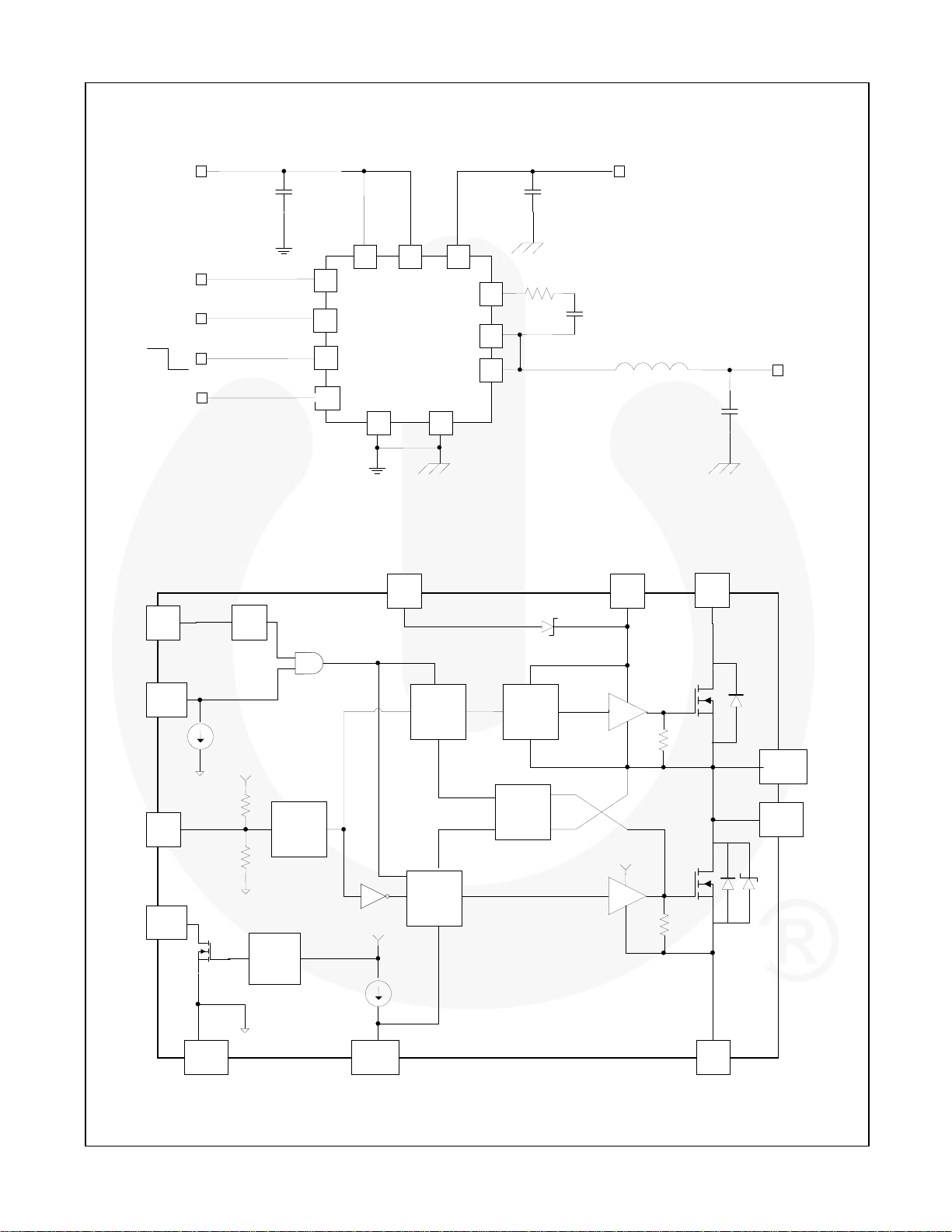
Typical Application Circuit
FDMF6707B - Extra-Small High-Performance, High-Frequency DrMOS Module
V5V
C
VDRV
DISB#
PWM Input
OFF
ON
Open Drain
Output
DrMOS Block Diagram
VCIN VIN
VDRV
R
DISB#
PWM
SMOD#
THWN#
FDMF6707B
CGND
PGND
BOOT
PHASE
VSWH
BOOT
Figure 1. Typical Application Circuit
VDRV
VIN
3V ~ 15V
C
VIN
C
BOOT
V
L
OUT
C
OUT
OUT
BOOT
VIN
VCIN
DISB#
PWM
THWN#
R
UP_PWM
R
DN_PWM
CGND
10µA
UVLO
V
CIN
Temp.
Sense
Input
3- State
Logic
D
Boot
GH
Logic
Level Shift
Dead-Time
Control
GL
Logic
V
CIN
10µA
SMOD#
Figure 2. DrMOS Block Diagram
Q1
HS Power
MOSFET
GH
30kΩ
PHASE
VSWH
V
DRV
GL
30kΩ
Q2
LS Power
MOSFET
PGND
© 2011 Fairchild Semiconductor Corporation www.fairchildsemi.com
FDMF6707B • Rev. 1.0.2 2
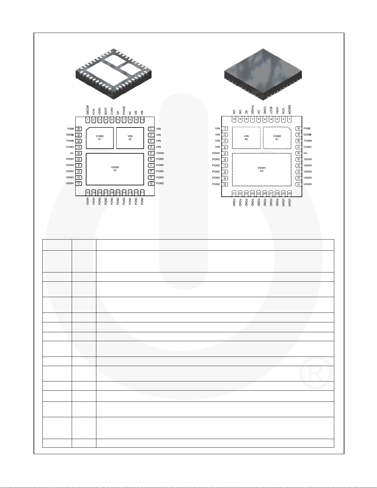
Pin Configuration
FDMF6707B - Extra-Small High-Performance, High-Frequency DrMOS Module
Figure 3. Bottom View Figure 4. Top View
Pin Definitions
Pin # Name Description
When SMOD#=HIGH, the low-side driver is the inverse of PWM input. When SMOD#=LOW,
1 SMOD#
2 VCIN IC bias supply. Minimum 1µF ceramic capacitor is recommended from this pin to CGND.
3 VDRV
4 BOOT
5, 37, 41 CGND IC ground. Ground return for driver IC.
6 GH For manufacturing test only. This pin must float. It must not be connected to any pin.
7 PHASE Switch node pin for bootstrap capacitor routing. Electrically shorted to VSWH pin.
8 NC
9 - 14, 42 VIN Power input. Output stage supply voltage.
15, 29 -
35, 43
16 – 28 PGND Power ground. Output stage ground. Source pin of the low-side MOSFET.
36 GL For manufacturing test only. This pin must float. It must not be connected to any pin.
38 THWN#
39 DISB#
40 PWM
VSWH
the low-side driver is disabled. This pin has a 10µA internal pull-up current source. Do not add a
noise filter capacitor.
Power for gate driver. Minimum 1µF ceramic capacitor is recommended connected as close as
possible from this pin to CGND.
Bootstrap supply input. Provides voltage supply to the high-side MOSFET driver. Connect a
bootstrap capacitor from this pin to PHASE.
No connect. The pin is not electrically connected internally, but can be connected to VIN for
convenience.
Switch node input. Provides return for high-side bootstrapped driver and acts as a sense point
for the adaptive shoot-through protection.
Thermal warning flag, open collector output. When temperature exceeds the trip limit, the
output is pulled LOW. THWN# does not disable the module.
Output disable. When LOW, this pin disables the power MOSFET switching (GH and GL are
held LOW). This pin has a 10µA internal pull-down current source. Do not add a noise filter
capacitor.
PWM signal input. This pin accepts a 3-state 3.3V
PWM signal from the controller.
© 2011 Fairchild Semiconductor Corporation www.fairchildsemi.com
FDMF6707B • Rev. 1.0.2 3
FDMF6707B - Extra-Small High-Performance, High-Frequency DrMOS Module
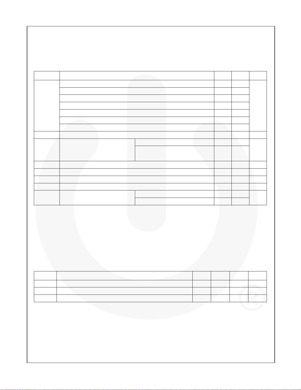
Absolute Maximum Ratings
Stresses exceeding the absolute maximum ratings may damage the device. The device may not function or be
operable above the recommended operating conditions and stressing the parts to these levels is not recommended.
In addition, extended exposure to stresses above the recommended operating conditions may affect device reliability.
The absolute maximum ratings are stress ratings only.
Symbol Parameter Min. Max. Unit
VCIN, VDRV, DISB#, PWM, SMOD#, GL, THWN# to CGND Pins -0.3 6.0
VIN to PGND, CGND Pins -0.3 25.0
BOOT, GH to VSWH, PHASE Pins -0.3 6.0
BOOT, PHASE, GH to CGND Pins -0.3 25.0
VSWH to CGND/PGND (DC Only) -0.3 25.0
VSWH to PGND (< 20ns) -8.0 25.0
BOOT to VDRV 22.0
I
THWN# Sink Current -0.1 7.0 mA
THWN#
(
I
Error!
O(AV)
Reference
source not
)
found.
θ
Junction-to-PCB Thermal Resistance 3.5 °C/W
JPCB
VIN=12V, VO=1.0V
f
=300kHz 50
SW
fSW=1MHz 45
TA Ambient Temperature Range -40 +125 °C
TJ Maximum Junction Temperature +150 °C
T
Storage Temperature Range -55 +150 °C
STG
ESD Electrostatic Discharge Protection
Human Body Model, JESD22-A114 2000
Charged Device Model, JESD22-C101 1000
Note:
1. I
is rated using Fairchild’s DrMOS evaluation board, at TA = 25°C, with natural convection cooling. This rating
O(AV)
is limited by the peak DrMOS temperature, T
= 150°C, and varies depending on operating conditions and PCB
J
layout. This rating can be changed with different application settings.
V
A
V
Recommended Operating Conditions
The Recommended Operating Conditions table defines the conditions for actual device operation. Recommended
operating conditions are specified to ensure optimal performance to the datasheet specifications. Fairchild does not
recommend exceeding them or designing to Absolute Maximum Ratings.
Symbol Parameter Min. Typ. Max. Unit
V
Control Circuit Supply Voltage 4.5 5.0 5.5 V
CIN
V
Gate Drive Circuit Supply Voltage 4.5 5.0 5.5 V
DRV
VIN Output Stage Supply Voltage
Note:
2. Operating at high VIN can create excessive AC overshoots on the VSWH-to-GND and BOOT-to-GND nodes
during MOSFET switching transients. For reliable DrMOS operation, VSWH-to-GND and BOOT-to-GND must
remain at or below the Absolute Maximum Ratings shown in the table above. Refer to the “Application
Information” and “PCB Layout Guidelines” sections of this datasheet for additional information.
(2)
3.0 12.0 15.0 V
© 2011 Fairchild Semiconductor Corporation www.fairchildsemi.com
FDMF6707B • Rev. 1.0.2 4
Electrical Characteristics
Typical values are VIN = 12V, V
Symbol Parameter Condition Min. Typ. Max. Unit
Basic Operation
IQ Quiescent Current IQ=I
UVLO UVLO Threshold V
UVLO
PWM Input (VCIN = VDRV = 5V +/- 10%)
R
R
V
V
V
V
t
D_HOLD-OFF
V
HiZ_PWM
PWM Input (VCIN = VDRV = 5V ±5%)
R
R
V
V
V
V
t
D_HOLD-OFF
V
HiZ_PWM
DISB# Input
V
V
t
PD_DISBL
t
PD_DISBH
SMOD# Input
V
IH_SMOD
V
t
PD_SLGLL
t
PD_SHGLH
UVLO Hysteresis 0.4 V
_Hyst
Pull-Up Impedance 26 kΩ
UP_PWM
Pull-Down Impedance 12 kΩ
DN_PWM
PWM High Level Voltage
IH_PWM
3-State Upper Threshold
TRI_HI
3-State Lower Threshold
TRI_LO
PWM Low Level Voltage
IL_PWM
3-State Shutoff Time 160 200 ns
3-State Open Voltage 1.40 1.60 1.90 V
Pull-Up Impedance 26 kΩ
UP_PWM
Pull-Down Impedance 12 kΩ
DN_PWM
PWM High Level Voltage
IH_PWM
3-State Upper Threshold
TRI_HI
3-State Lower Threshold
TRI_LO
PWM Low Level Voltage
IL_PWM
3-State Shutoff Time 160 200 ns
3-State Open Voltage 1.45 1.60 1.80 V
High-Level Input Voltage 2 V
IH_DISB
Low-Level Input Voltage 0.8 V
IL_DISB
I
Pull-Down Current 10 µA
PLD
Propagation Delay
Propagation Delay
High-Level Input Voltage 2 V
Low-Level Input Voltage 0.8 V
IL_SMOD
I
Pull-Up Current 10 µA
PLU
Propagation Delay
Propagation Delay
= 5V, V
CIN
= 5V, and T
DRV
VCIN+IVDRV
Rising 2.9 3.1 3.3 V
CIN
= +25°C unless otherwise noted.
A
, PWM=LOW or HIGH or Float 2 mA
1.88 2.25 2.61
1.84 2.20 2.56
0.70 0.95 1.19
0.62 0.85 1.13
2.00 2.25 2.50
1.94 2.20 2.46
0.75 0.95 1.15
0.66 0.85 1.09
PWM=GND, Delay Between DISB# from
HIGH to LOW to GL from HIGH to LOW
PWM=GND, Delay Between DISB# from
LOW to HIGH to GL from LOW to HIGH
PWM=GND, Delay Between SMOD# from
HIGH to LOW to GL from HIGH to LOW
PWM=GND, Delay Between SMOD# from
LOW to HIGH to GL from LOW to HIGH
25 ns
25 ns
10 ns
10 Ns
Continued on the following page…
FDMF6707B - Extra-Small High-Performance, High-Frequency DrMOS Module
V
V
V
V
V
V
V
V
© 2011 Fairchild Semiconductor Corporation www.fairchildsemi.com
FDMF6707B • Rev. 1.0.2 5
FDMF6707B - Extra-Small High-Performance, High-Frequency DrMOS Module
Electrical Characteristics
Typical values are VIN = 12V, V
Symbol Parameter Condition Min. Typ. Max. Unit
Thermal Warning Flag
T
Activation Temperature 150 °C
ACT
T
Reset Temperature 135 °C
RST
R
Pull-Down Resistance I
THWN
250ns Timeout Circuit
t
D_TIMEOUT
High-Side Driver
R
SOURCE_GH
R
t
D_DEADON
t
PD_PLGHL
t
PD_PHGHH
t
PD_TSGHH
Low-Side Driver
R
SOURCE_GL
R
t
D_DEADOFF
t
PD_PHGLL
t
PD_TSGLH
Boot Diode
Timeout Delay
Output Impedance, Sourcing Source Current=100mA 1 Ω
Output Impedance, Sinking Sink Current=100mA 0.8 Ω
SINK_GH
t
Rise Time GH=10% to 90%, C
R_GH
t
Fall Time GH=90% to 10%, C
F_GH
LS to HS Deadband Time
PWM LOW Propagation
Delay
PWM HIGH Propagation
Delay (SMOD# Held LOW)
Exiting 3-State Propagation
Delay
Output Impedance, Sourcing Source Current=100mA 1 Ω
Output Impedance, Sinking Sink Current=100mA 0.5 Ω
SINK_GL
t
Rise Time GL=10% to 90%, C
R_GL
t
Fall Time GL=90% to 10%, C
F_GL
HS to LS Deadband Time
PWM-HIGH Propagation
Delay
Exiting 3-State Propagation
Delay
VF Forward-Voltage Drop IF=10mA 0.35 V
VR Breakdown Voltage IR=1mA 22 V
= 5V, V
CIN
= 5V, and T
DRV
=5mA 30 Ω
PLD
SW=0V, Delay Between GH from HIGH to
LOW and GL from LOW to HIGH
GL going LOW to GH going HIGH,
1V GL to 10 % GH
PWM going LOW to GH going LOW,
V
IL_PWM
PWM going HIGH to GH going HIGH,
V
IH_PWM
PWM (from 3-State) going HIGH to GH
going HIGH, V
SW going LOW to GL going HIGH,
2.2V SW to 10% GL
PWM going HIGH to GL going LOW,
V
IH_PWM
PWM (from 3-State) going LOW to GL
going HIGH, V
= +25°C unless otherwise noted.
A
=1.1nF 6 ns
LOAD
=1.1nF 5 ns
LOAD
to 90% GH
to 10% GH (SMOD# =LOW)
to 10% GH
IH_PWM
=5.9nF 20 ns
LOAD
=5.9nF 13 ns
LOAD
to 90% GL
to 10% GL
IL_PWM
250 ns
10 ns
16 30 ns
30 ns
30 ns
12 ns
9 25 ns
20 ns
© 2011 Fairchild Semiconductor Corporation www.fairchildsemi.com
FDMF6707B • Rev. 1.0.2 6
 Loading...