

Page 1
www.fairchildsemi.com
FEB137-002 / FEB138-002
User Guide
FAN2001 / FAN2002
Evaluation Board
Featured Fairchild Product: FAN2001 / FAN2002
www.fairchildsemi.com/FEBsupport
© 2007 Fairchild Semiconductor Corporation FEB137/138_FAN2001/FAN2002 1 • Rev. 0.0.2
Page 2

www.fairchildsemi.com
Table of Contents
1. Features ..................................................................................................................................................3
2. Description .............................................................................................................................................3
3. Operation................................................................................................................................................3
4. PCB Layout............................................................................................................................................4
5. Waveforms .............................................................................................................................................4
6. Schematics..............................................................................................................................................5
7. Materials Lists........................................................................................................................................6
© 2007 Fairchild Semiconductor Corporation 2 FEB137/138_FAN2001/FAN2002 1 • Rev. 0.0.2
Page 3
www.fairchildsemi.com
The following user guide supports the evaluation kit for the FAN2001 and FAN2002. It
should be used in conjunction with the device datasheet as well as Fairchild application
notes and technical support team. Visit Fairchild’s website at www.fairchildsemi.com.
1. Features
2.5 to 5.5V Input Range
Up to 1A Output Current
Adjustable Output from 0.8V to V
Thermal Shutdown, Short-Circuit Protection, Soft Start, Output Over-Voltage Protection
1.3MHz Fixed-Frequency PWM Operation at Heavy Load and Burst Operation at Light Load
Up to 96% Efficiency, Synchronous Operation
Pb-Free, 6-lead 3x3mm MLP Package
2. Description
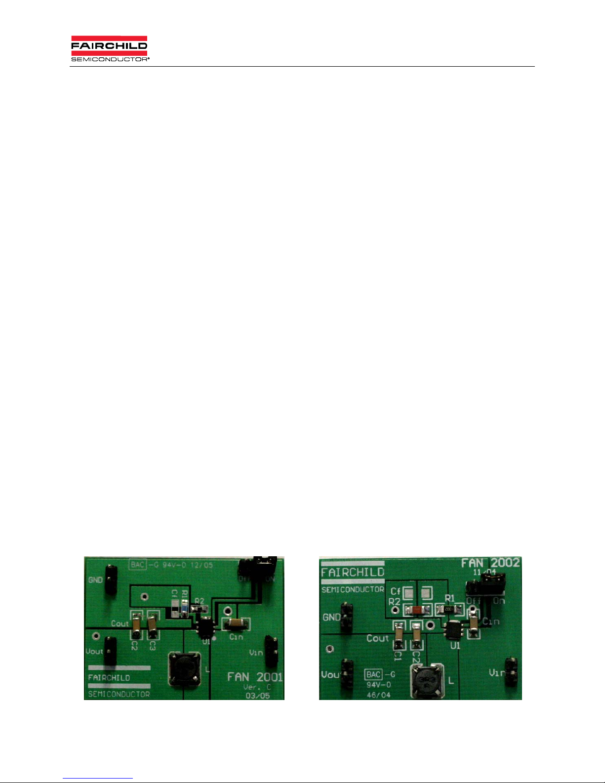
The FAN2001/2 Evaluation Board is a compact circuit including either the FAN2001
MPX or the FAN2002 MPX in a 3x3mm MLP package. Both models feature an external
resistor divider for varying output voltage and differ only in pin out. The FAN2001/2
demo board, a completely assembled and tested surface mount board, provides easy
probe access points to all inputs and outputs so that electrical characteristics and
waveforms can be easily measured.
IN
3. Operation
1. Connect VIN (2.5 to 5.5V) and GND (0V).
2. Use a jumper to toggle the circuit between "ON" and "OFF" modes.
3. Observe that, for varying input levels, if V
constant.
4. The output voltage level is V
10K. For V
Note: R2 and R1 values are reversed for FAN2002MPX.
5. To verify supply current in “ON” and “OFF” modes; observe that, in shutdown mode, supply
current drops below 1µA and in "ON" mode, I
6. If quiescent current is a key design parameter, a higher value feedback resistor R2 can be
used, along with a small bypass capacitor C
OUT
> V
IN
OUT
OUT
= V
(1 + (R1/R2)) where V
REF
= 1.2V, R1 is preset to 5K and for V
< 50µA.
Q
(e.g. R2 = 100K and CF = 10pF).
F
+ 0.6V and I
= 3.3V, R1 is preset to 31.25K.
OUT
< 1A, V
LOAD
= 0.8V (typical) and R2 =
REF
remains
OUT
Figure 1. FAN2001MPX Board Figure 2. FAN2002MPX Board
© 2007 Fairchild Semiconductor Corporation 3 FEB137/138_FAN2001/FAN2002 1 • Rev. 0.0.2
Page 4

www.fairchildsemi.com
4. PCB Layout
Figure 3. FAN2001MPX PCB Layout
5. Waveforms
Figure 4. FAN2002MPX PCB Layout
Figure 5. Start-Up Waveform in Full Load (VIN=5.5V)
© 2007 Fairchild Semiconductor Corporation 4 FEB137/138_FAN2001/FAN2002 1 • Rev. 0.0.2
Page 5

www.fairchildsemi.com
6. Schematics
V
IN
C
10µF
ON
OFF
1
VIN
IN
2
PGND
3
EN
VOUT
P1
Note: Cf is OPEN (not installed on regular eval board.)
NC
FB
6
5
L
3.3µH
R1
Cf
C2
10µFC310µF
4
R2
10K
V
OUT
Figure 6. FAN2001MPX Schematic (R1 = 5K for V
= 1.2V and R1 = 31.25K for V
OUT
OFF
= 3.3V)
OUT
ON
V
IN
1
FB
EN
6
R1
L
3.3µH
10K
2
3
PGND
SW
P1
PVIN
= 1.2V and R1 = 31.25K for V
OUT
VIN
5
4
C
IN
10µF
OUT
= 3.3V)
R2
V
OUT
C1
10µF
Figure 7. FAN2002MPX Schematic (R1 = 5K for V
© 2007 Fairchild Semiconductor Corporation 5 FEB137/138_FAN2001/FAN2002 1 • Rev. 0.0.2
Cf
C2
10µF
Page 6

www.fairchildsemi.com
7. Materials Lists
Table 1. FAN2001MPX List of Materials
Description Qty. Ref. Vendor Part Number
Inductor 3.3µH, I
Capacitor 10µF, 10%, 6.3V, X5R, 1206 3 C2, C3, CIN
Resistor 10Kohm, 1%, 1206 1 R2 Any
Resistor 31.25Kohm, 1%, 0805
(for option V
Resistor 4.99Kohm, 1%, 0805
(for option V
Hardware Connector Header .
1 SINGLE STR 36POS
IC DC/DC Regulator, 6-lead MLP 3x3mm,
FSID: FAN2001MPX
Hardware, SHUNT, PHBR 15AU 1 ON/OFF DIGI-KEY A26227-ND
Table 2. FAN2002 MPX List of Materials
= 0.5A 1 L Any
sat
MURATA
Panasonic
set 3.3V)
OUT
set 1.2V)
OUT
1 R1 Any
1 R1 Any
VIN, V
9
1 U1
, GND,
OUT
ON/OFF
Digi-Key
Fairchild
Semiconductor
GRM31CR70J106K
ECJ-3YB0J106K
S1011-36-ND
FAN2001MPX
Description Qty. Ref. Vendor Part Number
Inductor 3.3µH, I
Capacitor 10µF, 10%, 6.3V, X5R, 1206 3 C1, C2, CIN
Resistor 10Kohm, 1%, 1206 1 R1 Any
Resistor 31.25Kohm, 1%, 1206
(for option V
Resistor 4.99Kohm, 1%, 1206
(for option V
Hardware Connector Header
.1 SINGLE STR 36POS
IC DC/DC Regulator, 6-lead MLP 3x3mm,
FSID: FAN2002MPX
Hardware, SHUNT, PHBR 15AU 1 ON/OFF DIGI-KEY A26227-ND
= 0.5A 1 L Any
sat
MURATA
Panasonic
VIN, V
ON/OFF
R2
R2
OUT
U1
, GND,
Any
Any
Digi-Key
Fairchild
Semiconductor
set 3.3V)
OUT
set 1.2V)
OUT
1
1
9
1
GRM31CR70J106K
ECJ-3YB0J106K
S1011-36-ND
FAN2002MPX
Table 3. Ordering Information
Product Number Package Type Order Code
FAN2001 Pb-Free, 6-Lead 3x3mm Molded Leadless Package (MLP) FAN2001MPX
FAN2002 Pb-Free, 6-Lead 3x3mm Molded Leadless Package (MLP) FAN2002MPX
© 2007 Fairchild Semiconductor Corporation 6 FEB137/138_FAN2001/FAN2002 1 • Rev. 0.0.2
Page 7

www.fairchildsemi.com
TRADEMARKS
The following are registered and unregistered trademarks Fairchild Semiconductor owns or is authorized to use and is not intended to be an
exhaustive list of all such trademarks.
®
ACEx
Across the board.
Around the world.™
ActiveArray™
Bottomless™
Build it Now™
CoolFET™
CorePLUS™
CROSSVOLT™
CTL™
Current Transfer Logic™
DOME™
2
CMOS™
E
EcoSPARK
®
EnSigna™
FACT Quiet Series™
®
FACT
®
FAST
FASTr™
FPS™
WARNING AND DISCLAIMER
Replace components on the Evaluation Board only with those parts shown on the parts list (or Bill of Materials) in the Users’
Guide. Contact an authorized Fairchild representative with any questions.
The Evaluation board (or kit) is for demonstration purposes only and neither the Board nor this User’s Guide constitute a sales
contract or create any kind of warranty, whether express or implied, as to the applications or products involved. Fairchild warrantees
that its products meet Fairchild’s published specifications, but does not guarantee that its products work in any specific application.
Fairchild reserves the right to make changes without notice to any products described herein to improve reliability, function, or
design. Either the applicable sales contract signed by Fairchild and Buyer or, if no contract exists, Fairchild’s standard Terms and
Conditions on the back of Fairchild invoices, govern the terms of sale of the products described herein.
DISCLAIMER
FAIRCHILD SEMICONDUCTOR RESERVES THE RIGHT TO MAKE CHANGES WITHOUT FURTHER NOTICE TO ANY
PRODUCTS HEREIN TO IMPROVE RELIABILITY, FUNCTION, OR DESIGN. FAIRCHILD DOES NOT ASSUME ANY
LIABILITY ARISING OUT OF THE APPLICATION OR USE OF ANY PRODUCT OR CIRCUIT DESCRIBED HEREIN;
NEITHER DOES IT CONVEY ANY LICENSE UNDER ITS PATENT RIGHTS, NOR THE RIGHTS OF OTHERS.
LIFE SUPPORT POLICY
FAIRCHILD’S PRODUCTS ARE NOT AUTHORIZED FOR USE AS CRITICAL COMPONENTS IN LIFE SUPPORT DEVICES
OR SYSTEMS WITHOUT THE EXPRESS WRITTEN APPROVAL OF THE PRESIDENT OF FAIRCHILD SEMICONDUCTOR
CORPORATION.
As used herein:
1. Life support devices or systems are devices or systems
which, (a) are intended for surgical implant into the body, or
(b) support or sustain life, or (c) whose failure to perform
when properly used in accordance with instructions for use
provided in the labeling, can be reasonably expected to
result in significant injury to the user.
®
FRFET
GlobalOptoisolator™
GTO™
HiSeC™
i-Lo™
ImpliedDisconnect™
IntelliMAX™
ISOPLANAR™
MICROCOUPLER™
MicroPak™
MICROWIRE™
Motion-SPM™
MSX™
MSXPro™
OCX™
OCXPro™
OPTOLOGIC
OPTOPLANAR
®
®
PACMAN™
PDP-SPM™
POP™
Power220
Power247
®
®
PowerEdge™
PowerSaver™
Power-SPM™
PowerTrench
Programmable Active Droop™
QFET
®
®
QS™
QT Optoelectronics™
Quiet Series™
RapidConfigure™
RapidConnect™
ScalarPump™
SMART START™
®
SPM
STEALTH™
SuperFET™
SuperSOT™-6
SuperSOT™-8
SyncFET™
TCM™
The Power Franchise
™
TinyBoost™
TinyBuck™
TinyLogic
®
TINYOPTO™
TinyPower™
TinyWire™
TruTranslation™
μSerDes™
®
UHC
UniFET™
VCX™
Wire™
SuperSOT™-3
2. A critical component is any component of a life support
device or system whose failure to perform can be
reasonably expected to cause the failure of the life support
device or system, or to affect its safety or effectiveness.
®
I27
© 2007 Fairchild Semiconductor Corporation 7 FEB137/138_FAN2001/FAN2002 1 • Rev. 0.0.2
Page 8

Mouser Electronics
Authorized Distributor
Click to View Pricing, Inventory, Delivery & Lifecycle Information:
Fairchild Semiconductor:
FEB137
 Loading...