

Fairchild CD4051BC, CD4052BC,CD4053BC Datasheet
November 1983
Revised August 2000
CD4051BC • CD4052BC • CD4053BC
Single 8-Channel Analog Multiplexer/Demultiplexer •
Dual 4-Channel Analog Multiplexer/Demultiplexer •
Triple 2-Channel Analog Multiplexer/Demultiplexer
CD4051BC • CD4052BC • CD4053BC Single 8-Channel Analog Mul tiplexer/Demultiplexe r • Dual 4-Channel Analog
Multiplexer/Demultiplexer • Triple 2-Channel Analog Mult iplexer/Demultiplexer
General Description
The CD4051BC, CD4 052BC, an d CD405 3BC anal og multiplexers/demultiplexers are digitally controlled analog
switches having low “ON” impedance and very low “OFF”
leakage currents. Cont rol of analog signals up to 15V
can be achieved by d igital s ignal amplit udes o f 3−15V. For
example, if V
nals from
0
−5V. The multiplexer circuits dissipate extremely low qui-
escent power over the full V
voltage ranges, independent of the logic state of the control
signals. When a logical “1” is present at the inhibit input terminal all channels are “OFF”.
CD4051BC is a single 8-c hannel multiplexe r having three
binary control input s. A , B, and C, and an i nh ibit i n put . T he
three binary signals select 1 of 8 channels to be turned
“ON” and connect the input to the output.
CD4052BC is a differential 4-channel multiplexer having
two binary control inputs, A and B, and an inhibit input. The
two binary input sig nals select 1 or 4 pairs of channels to
be turned on and connect the differen tial analog inputs to
the differential outputs.
CD4053BC is a triple 2-channel multiplexer having three
separate digital con trol inputs, A, B , and C, and an i nhibit
input. Each control in put selects one of a pair of ch annels
which are connected in a single-pole double-throw configuration.
= 5V, V
DD
−5V to +5V can be contro lled by dig ital input s of
= 0V and V
SS
DD−VSS
= −5V, analog sig-
EE
and V
DD−VEE
supply
Features
■ Wide range of digital and analog signal levels:
digital 3 – 15V, analog to 15V
■ Low “ON” resistance: 80Ω (typ.) over entire 15V
p-p
signal-i nput range for V
■ High “OFF” resistance:
channel leakage of
■ Logic level conversion for digital addressing signals of
3 – 15V (V
to 15 V
■ Matched switch characteristics:
∆R
ON
■ Very low quiescent power dissipation under all
digital-control input and supply conditions:
1
µ W (typ.) at V
■ Binary address decoding on chip
− V
DD
SS
(V
− V
p-p
DD
EE
= 5Ω (typ.) for V
DD
p-p
− V
= 15V
DD
EE
±10 pA (typ.) at V
= 3 – 15V) to switch analog signals
= 15V)
− V
DD
− V
= V
SS
EE
DD
= 15V
− V
DD
EE
= 10V
− V
EE
p-p
= 10V
Ordering Code:
Order Number Package Number Package Description
CD4051BCM M16A 16-Lead Small Outline Integrated Circuit (SOIC), JEDEC MS-012, 0.150 Narrow
CD4051BCSJ M16D 16-Lead Small Outline Package (SOP), EIAJ TYPE II, 5.3mm Wide
CD4051BCMTC MTC16 16-Lead Thin Shrink Small Outline Package (TSSOP), JEDEC MO-153, 4.4mm Wide
CD4051BCN N16E 16-Lead Plastic Dual-In-Line Package (PDIP), JEDEC MS-001, 0.300 Wide
CD4052BCM M16A 16-Lead Small Outline Integrated Circuit (SOIC), JEDEC MS-012, 0.150 Narrow
CD4052BCSJ M16D 16-Lead Small Outline Package (SOP), EIAJ TYPE II, 5.3mm Wide
CD4052BCN N16E 16-Lead Plastic Dual-In-Line Package (PDIP), JEDEC MS-001, 0.300 Wide
CD4053BCM M16A 16-Lead Small Outline Integrated Circuit (SOIC), JEDEC MS-012, 0.150 Narrow
CD4053BCSJ M16D 16-Lead Small Outline Package (SOP), EIAJ TYPE II, 5.3mm Wide
CD4053BCN N16E 16-Lead Plastic Dual-In-Line Package (PDIP), JEDEC MS-001, 0.300 Wide
Devices also availab l e in Tape and Reel. Specify by appending th e s uffix let t er “X” to the ordering code.
© 2000 Fairchild Semiconductor Corporation DS005662 www.fairchildsemi.com
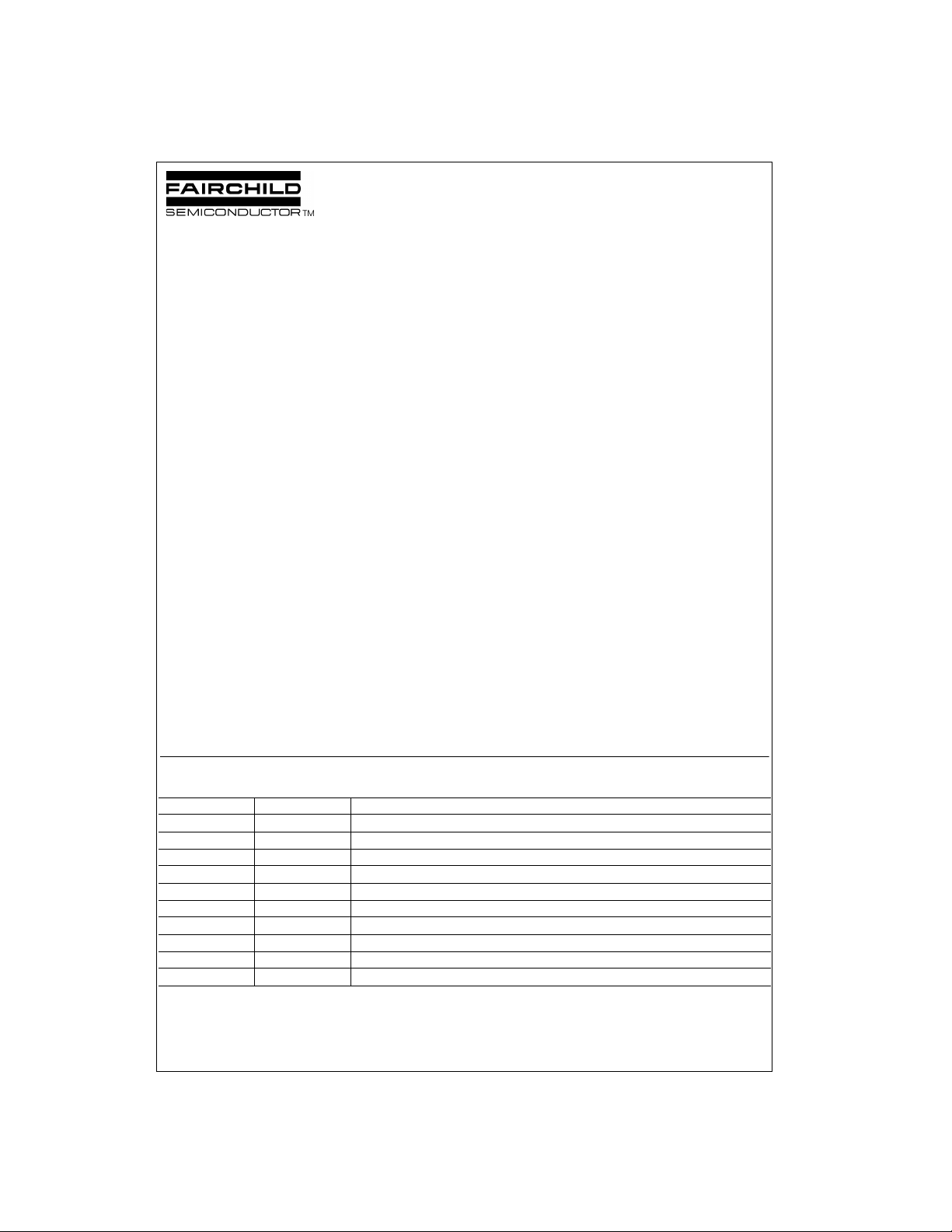
Connection Diagrams
Pin Assignments for DIP and SOIC
CD4051BC CD4052BC
CD4051BC • CD4052BC • CD4053BC
CD4053BC
Truth Table
INPUT STATES “ON” CHANNELS
INHIBIT C B A CD4051B CD4052B CD4053B
0 0 0 0 0 0X, 0Y cx, bx, ax
0 0 0 1 1 1X, 1Y cx, bx, ay
0 0 1 0 2 2X, 2Y cx, by, ax
0 0 1 1 3 3X, 3Y cx, by, ay
0 1 0 0 4 cy, bx, ax
0 1 0 1 5 cy, bx, ay
01106 cy, by, ax
01117 cy, by, ay
*Don’t Care condition.
www.fairchildsemi.com 2
1 * * * NONE NONE NONE
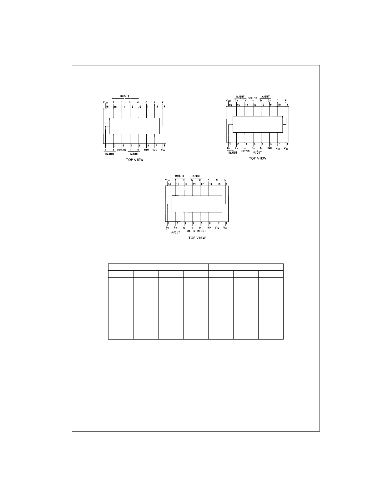
Logic Diagrams
CD4051BC • CD4052BC • CD4053BC
CD4051BC
CD4052BC
3 www.fairchildsemi.com
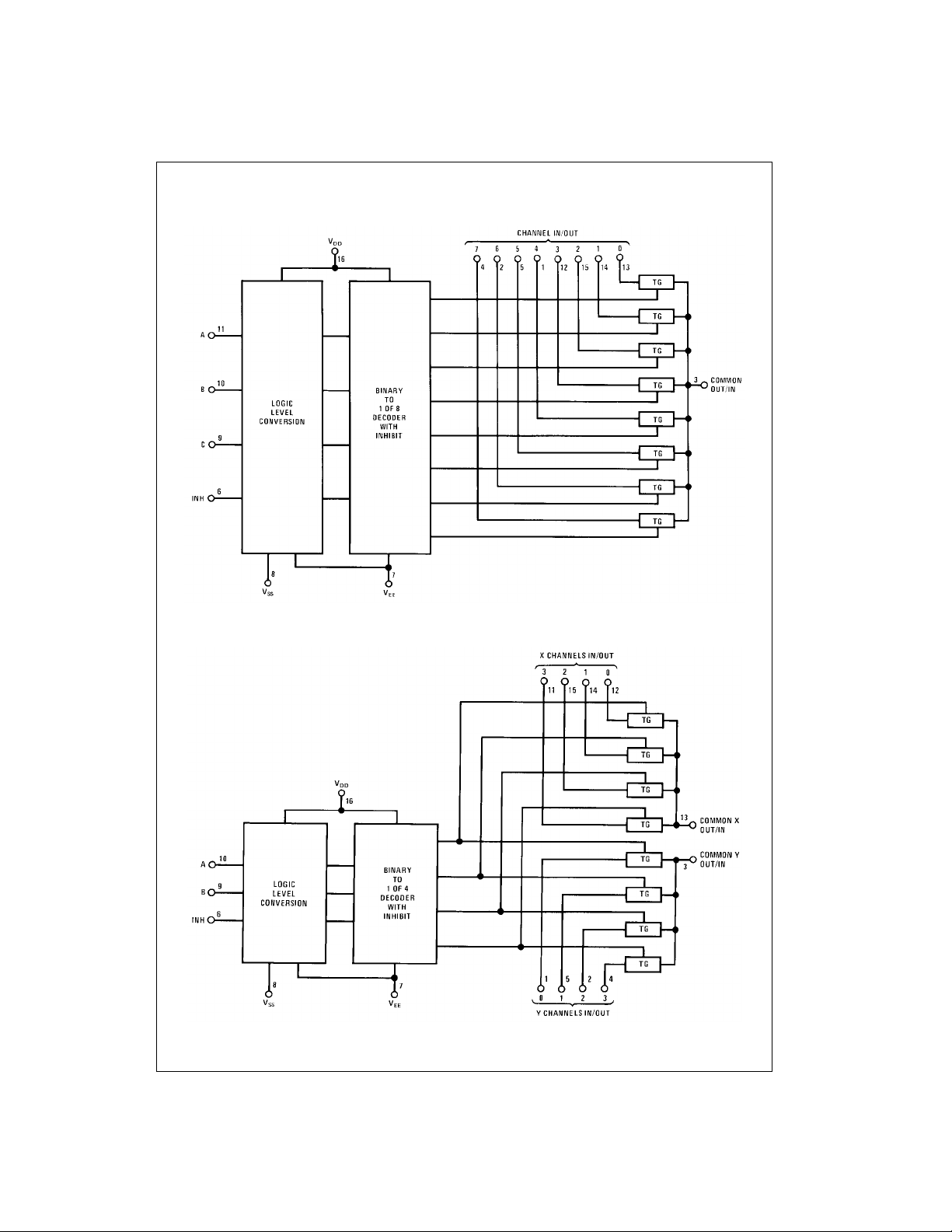
Logic Diagrams (Continued)
CD4051BC • CD4052BC • CD4053BC
CD4053BC
www.fairchildsemi.com 4
 Loading...