

Page 1
PRELIMINARY
OSPREY CAMERA SERIES
CAM/CCD-2KLV.TDI
CAM/CCD-4KLV.TDI
ULTRA-HIGH PERFORMANCE
Line Scan Camera
Camera User’s Manual
Page 2

PRELIMINARY
FAIRCHILD IMAGING
OSPREY CAMERA SERIES
USER’S MANUAL
CAM/CCD-2KLV.TDI and CAM/CCD-4KLV.TDI
Rev 073004
© 2004 Fairchild Imaging, Inc.
Fairchild Imaging, Inc.
1801 McCarthy Blvd.
Milpitas CA 95035
1-800-325-6975
www.fairchildimaging.com
PRELIMINARY DOCUMENT
The information in this manual is preliminary.
All information provided in this manual is believed to be correct at the
time of writing. No responsibility is assumed by Fairchild Imaging for
its use. Fairchild Imaging intends to make this manual as accurate as
possible and reserves the right to make changes to this information
without notice.
Fairchild Imaging • CAM/CCD-2KLV.TDI & CAM/CCD-4KLV.TDI Line Scan Camera User’s Manual • Rev 073004 • 2 of 38
Page 3

PRELIMINARY
Table of Contents
SECTION 1
Introduction to the CAM/CCD-2KLV.TDI and CAM/CCD-4KLV.TDI
High Performance TDI Line Scan Camera ...................................................................... 5
1.1 Camera Highlights ....................................................................................................... 5
1.2 Camera Specification................................................................................................... 6
1.3 Image Sensor............................................................................................................... 7
1.4 Block Diagram CCD525............................................................................................... 8
1.5 Block Diagram CCD545............................................................................................... 9
1.6 Block Diagram 2K and 4K TDI Camera ....................................................................... 10
1.7 2K/4K TDI Camera Timing Diagram ............................................................................ 11
1.8 Thermal Considerations............................................................................................... 12
SECTION 2
Camera Hardware Interface ............................................................................................. 13
2.1 Installation Overview.................................................................................................... 13
2.2 Connectors, Pinouts and Cables ................................................................................. 14
2.3 Power Supply............................................................................................................... 16
2.4 LED Indicator Status Lamp .......................................................................................... 16
SECTION 3
Camera Control ................................................................................................................. 17
3.1 Quick Start with LVDS Interface .................................................................................. 17
3.2 Control Inputs............................................................................................................... 17
3.3 Providing External Triggering....................................................................................... 18
3.4 Frame Grabber Receives Trigger ................................................................................ 19
3.5 Frame Mode................................................................................................................. 20
3.6 System Connection...................................................................................................... 22
3.7 TDI Length Selection ................................................................................................... 23
3.8 Gain and Offset Calibration.......................................................................................... 24
3.9 How to Modify Gain & Offset Values............................................................................ 24
3.10 Data Bus ..................................................................................................................... 25
SECTION 4
Mechanical and Optical Considerations......................................................................... 26
4.1 Camera Dimensions and Mounting.............................................................................. 26
4.2 Lenses ......................................................................................................................... 27
4.3 Mechanical Drawing of Optical Camera Face Mounting “L” Bracket ........................... 28
4.4 Lenses ......................................................................................................................... 28
4.5 Positioning Accuracy of the Sensor Chip in the Camera ............................................. 29
4.6 Illumination................................................................................................................... 29
4.7 Light Sources ............................................................................................................... 29
4.8 Lens Modeling.............................................................................................................. 30
4.9 2K and 4K LVDS Cable Harness ................................................................................. 30
Fairchild Imaging • CAM/CCD-2KLV.TDI & CAM/CCD-4KLV.TDI Line Scan Camera User’s Manual • Rev 073004 • 3 of 38
Page 4

PRELIMINARY
SECTION 5
Handling Instructions ....................................................................................................... 31
5.1 Electrostatic Discharge ................................................................................................ 31
5.2 Preventing ESD Damage............................................................................................. 31
5.3 Protecting Against Dust, Oil and Scratches ................................................................. 31
5.4 Cleaning the Sensor Window....................................................................................... 31
SECTION 6
Troubleshooting................................................................................................................ 32
6.1 Check Simple Things First ........................................................................................... 32
6.2 Use the Camera Control Interface to Perform Checks ................................................ 32
6.3 Other Areas You Should Check................................................................................... 32
SECTION 7
Product Support................................................................................................................ 35
REFERENCE A
Providing External Trigger Using PCI-1424 Frame Grabber......................................... 36
REFERENCE B
Introduction to LVDS ........................................................................................................ 37
Fairchild Imaging • CAM/CCD-2KLV.TDI & CAM/CCD-4KLV.TDI Line Scan Camera User’s Manual • Rev 073004 • 4 of 38
Page 5

SECTION 1
CAM/CCD-2KLV.TDI and CAM/CCD-4KLV.TDI
PRELIMINARY
Introduction to the
High Performance TDI Line Scan Camera
1.1 Camera Highlights
Description
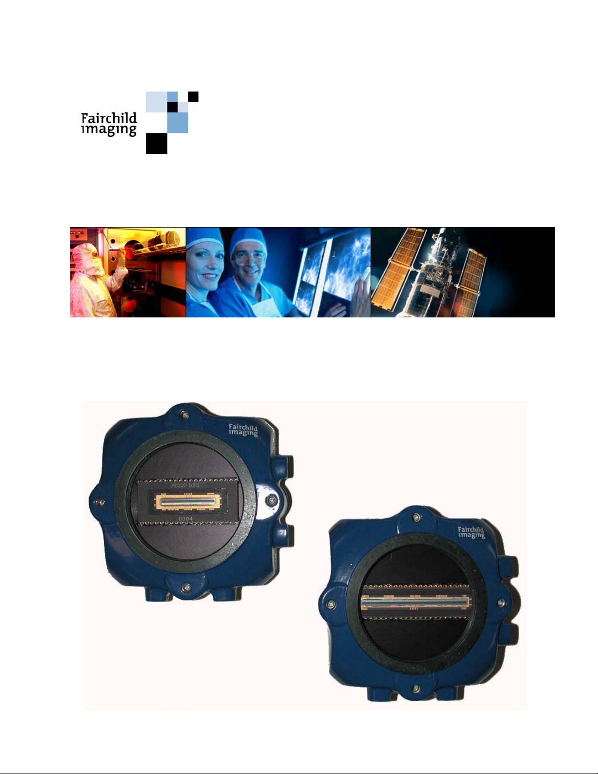
The Osprey TDI camera series is an ultra-sensitive camera design for use in line scan
applications that demand high performance under low light conditions. This series of
cameras is based upon Fairchild’s CCD525 array, which is used in the very successful U.S.
Postal Service Wide Field of View (WFOV) Camera. The 2K camera versions have 2048
pixels in the cross-scan direction, with selectable TDI stages up to 96 rows. The 4K
varieties have 4096 pixels in the cross-scan direction, also with selectable TDI stages up to
96 rows. The 2K Osprey supports scan rates up to 46K lines per second while the 4K
yields up to 23K lines per second. Both the 2K and 4K styles have LVDS outputs. The
LVDS output supports 4-port, 8-bit synchronous data. This camera also includes
sophisticated features such as anti-blooming, programmable gain and offset. It is packaged
in a very compact and rugged housing that contains a standard M58 x 0.75 base lens
thread. Optional (Nikon-F) lens adapter is available.
2K x 96 TDI Sensor Architecture
• Uses time delay and integration sensor architecture
• User selectable TDI lengths of 96, 64, 48, 32
• Line rate up to 46K lines per sec
• 1000X antiblooming
• Non volatile gain/offset value memory
• <1 LSB Noise RMS
4K x 96 TDI Sensor Architecture
• Uses time delay and integration sensor architecture
• User selectable TDI lengths of 96, 64, 32, 16
• 25MHz pixel clock
• Non volatile gain/offset value memory
• <1 LSB Noise RMS
Fairchild Imaging • CAM/CCD-2KLV.TDI & CAM/CCD-4KLV.TDI Line Scan Camera User’s Manual • Rev 073004 • 5 of 38
Page 6

PRELIMINARY
Programmability
Simple menu-based configuration for selection of gain, offset operational control, and
diagnostics.
• LVDS camera-PC communications with Fairchild-supplied user GUI.
Usability
Programmable gain, offsets, and controls.
• Easy integration “plug compatabile” LVDS hookup
Full Spectrum of Applications
• Precision manufacturing inspection
• Web inspection
• Sorting and routing
• Biomedical readout systems
• Diagnostic systems
1.2 Camera Specification – CAM/CCD-2KLV.TDI & CAM/CCD-4KLV.TDI Performance Specification
Calibration Conditions Units Min. 2048
Data Rate (Strobe) MHz 25 25 25 25
Line Rate (LVAL) KHz 0.3 46.0 0.3 23 8
Functions
Saturation Output Amplitude DN 250 255 250 255
Output Gain Mismatch DN 2 5 2 5
Pixel Response Non-Uniformity Global DN 5 12 5 12
(PRNU) Tap DN 4 10 4 10 1, 3,4
Pixel-Pixel DN 4 10 4 10 7
Fixed Pattern Moise (FPN) Global DN 3 3 3,4
Tap DN 2 2 1, 3
Pixel-Pixel DN 2 2 3, 4
DC Offset DN 4 4 2
DC Offset Mismatch DN 2 2
Random Noise DN 2 4 2 4
Noise Equivalent Exposure
Saturation Equivalent Exposure
Responsivity
Dynamic Range Ratio 360:1 360:1
Power Supply Current @ 12VDC mA 650 700 6,9
Power Supply Voltage Volts 10.5 15.0 10.5 15.0
Operating Temperature
First Pixel Mismatch DN 5
2
pJ/cm
2
nJ/cm
DN/(nJ/cm
°C
Typ.
3 3
1.0 1.0
2
250 250
)
40 40
Max. Min 4096
Typ.
Max. Notes
Fairchild Imaging • CAM/CCD-2KLV.TDI & CAM/CCD-4KLV.TDI Line Scan Camera User’s Manual • Rev 073004 • 6 of 38
Page 7

PRELIMINARY
Notes:
DN = Digital Numbers, also known as “levels” (0 – 255 for 8-bit systems, 0 – 4095 for 12-bit
systems).
All measurements taken with camera operating in 96 stage mode.
All measurements exclude the last pixel of OS 1 and the first pixel of OS4.
Tested using volpi (18111.001) linght line source, default camera gain.
1. Measured across 1 tap (512 pixels – 2K) (1024 pixels – 4K).
2. Typical offset @ 20°C ambient.
3. Excludes last pixel of OS1 and first pixel.
4. Measured across all taps.
5. Measured on each tap relative to next ten pixels. Measured at Vsat.
6. Measured with digital outputs, (terminated in 100 ohms).
7. A delta window of 8 pixels is examined and shifted by half its window. First and last
pixel excluded from each tap.
8. Camera will operate below min. line rate with degraded performance.
9. Power supply must support >850 mA surge current.
1.3 Image Sensor
The family of Osprey cameras use the following Fairchild sensors: The 2K x 96 TDI
camera uses the CCD525 sensor, and the 4K x 96 TDI camera uses the CCD545 sensor.
Both sensors have 13µm square pixels on a 13µm pitch.
Both sensors are approximately 96 times more sensitive compared to line scan cameras.
Fairchild Imaging • CAM/CCD-2KLV.TDI & CAM/CCD-4KLV.TDI Line Scan Camera User’s Manual • Rev 073004 • 7 of 38
Page 8

1.4 Block Diagram CCD525
PRELIMINARY
2048 x 96 stages
Fairchild Imaging • CAM/CCD-2KLV.TDI & CAM/CCD-4KLV.TDI Line Scan Camera User’s Manual • Rev 073004 • 8 of 38
Page 9
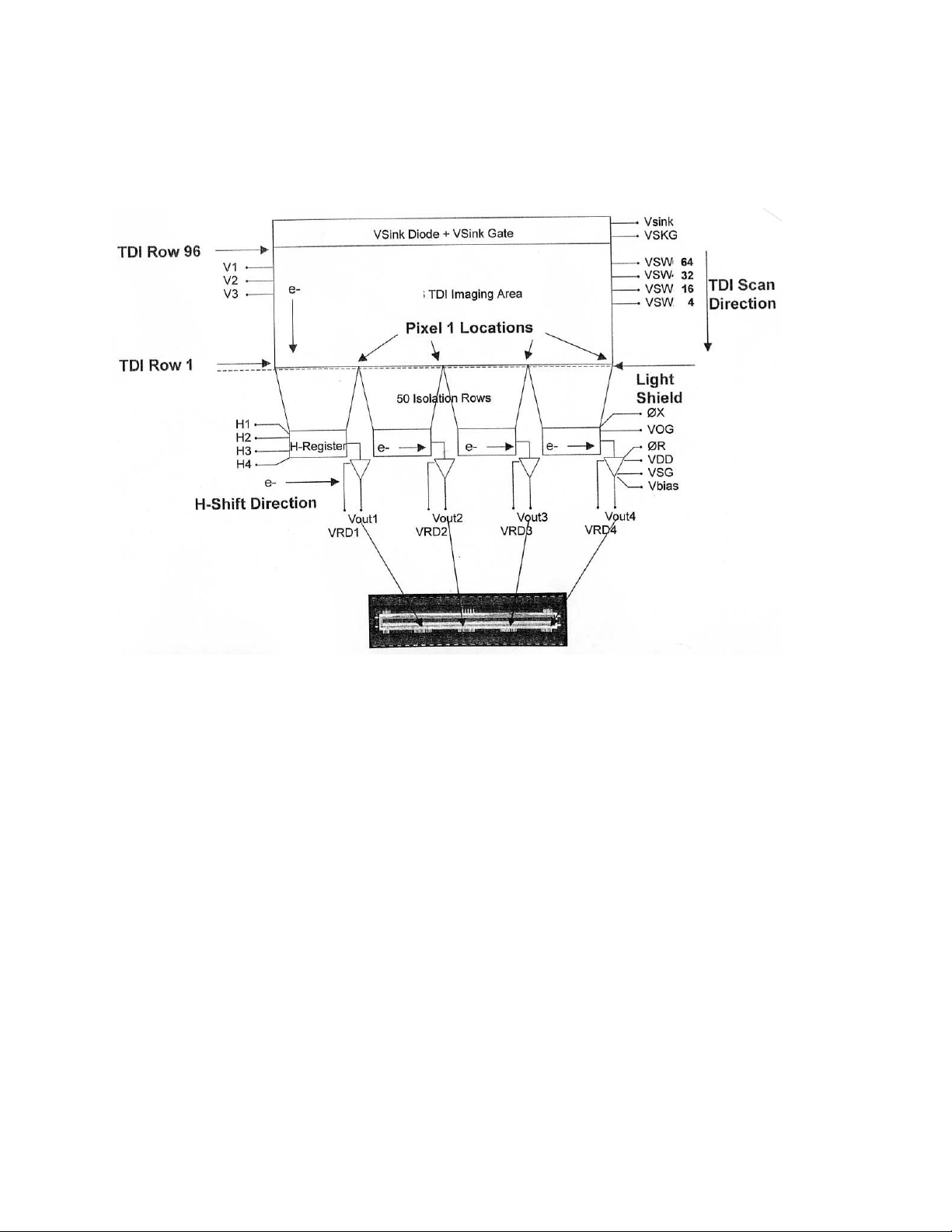
1.5 Block Diagram CCD545
4096 x 96 stages
PRELIMINARY
Fairchild Imaging • CAM/CCD-2KLV.TDI & CAM/CCD-4KLV.TDI Line Scan Camera User’s Manual • Rev 073004 • 9 of 38
Page 10
PRELIMINARY
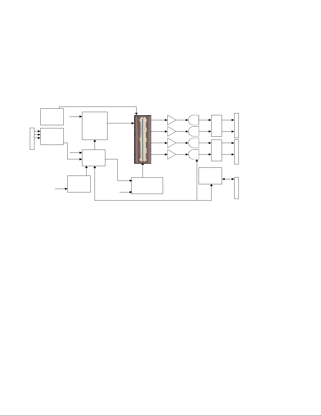
1.6 Block Diagram 2K & 4K TDI Camera
.
.
.
.
.
.
.
.
.
.
.
.
.
.
.
J4
Inp ut
Power
+12.0V
GND
DC
BIAS
SUPP.
GEN’L
PW R
SUPP.
Outputs
+14V
+10V
+5.2A
+5.0D
+3.3D
+3.0A
-2V
-6V
+3.3
+5.2
+3.3
50MHz
Master
Clock
25.0MH z
Hi Speed
Clock
Drivers
H1 /2/3/4 O R
/
5
Timing
& I / O
Control
/
7
CCD
Sensor
/
Low Speed
5
Clock
+10
Drivers
V1 /2/3 OX VS Wx
Fa irc h ild Im agi ng
Analog
Buffers
/
5
Video
Processo rs
+3.3D+3.0A +3.3D+14V
44
33
22
11
SHP SHD
/
8
/
8
/
8
/
8
LVDS
Buffers
I / O
Buffers
Data Out
Connectors
. .
. .
. .
/
. .
8
. .
J7
. .
. .
/
. .
. .
8
. .
. .
/
. .
8
. .
. .
J8
. .
/
. .
8
. .
. .
Mode
Connector
.
/
.
.
J5
.
3
.
.
.
.
.
.
.
.
.
.
.
Fair child CA M-4 k TD I.p pt 4
Fairchild Imaging • CAM/CCD-2KLV.TDI & CAM/CCD-4KLV.TDI Line Scan Camera User’s Manual • Rev 073004 • 10 of 38
Page 11
PRELIMINARY
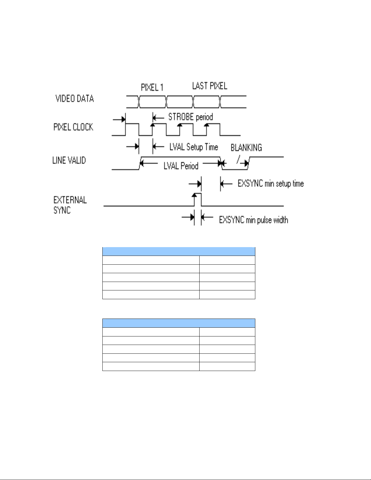
1.7 2K/4K TDI Camera Timing Diagram
Note: Timing diagram not to scale
2K TDI LVDS
Strobe period :40 nS
LVAL set-up time :20 nS
Line period (min.) :21.8 uS
Blanking :0.8 uS
ExSync min pulse width :120 ns
4K TDI LVDS
Strobe period :40 nS
LVAL set-up time :20 nS
Line period (min.) :43.1 uS
Blanking :2.15 uS
ExSync min pulse width :120 ns
Fairchild Imaging • CAM/CCD-2KLV.TDI & CAM/CCD-4KLV.TDI Line Scan Camera User’s Manual • Rev 073004 • 11 of 38
Page 12

PRELIMINARY
1.8 Thermal Considerations
The Osprey camera series has been thermally designed to separate the camera electronics
from the image sensor.
The sensor temperature is thermally linked near the four M4 mounting holes on the face of
the camera. Fairchild Imaging recommends mounting the camera using these holes to
minimize sensor dark current artifacts.
Fairchild Imaging recommends that gain or offset corrections are completed after the
camera has been turned on for at least 15 minutes. To do offset correction, cover the lens
with your lens cap Follow this by removing the lens cap to complete a gain calibration.
Make sure that gain calibration is completed with a uniform light source, illuminating the
camera Field-Of-View (FOV).
Avoid excess ambient temperatures around the camera.
Fairchild Imaging • CAM/CCD-2KLV.TDI & CAM/CCD-4KLV.TDI Line Scan Camera User’s Manual • Rev 073004 • 12 of 38
Page 13

PRELIMINARY
SECTION 2
Camera Hardware Interface
2.1 Installation Overview
Before you integrate your camera into your system you should first determine some basic
operating parameters such as what resolution you need. Do you know the speed of the
object that your camera will be inspecting? One additional point you want to keep in mind
is your lighting requirement.
Some other major items that you should identify early on in developing your system is the
source of your EXSYNC control signal (framegrabber, custom controller, shaft/web
encoder, etc.). You should also know—in advance—your sensor resolution and
magnification requirements.
We will use a simple example to reinforce what we just told you in the above. Let’s say that
you have the following system to set up: inspect a web 10cm wide, moving at 2m/s, and
you want 100µm on the web to be represented by one pixel (7µm).
Number of Pixels Total width of image
Necessary Desired resolution 100µm per pixel
Magnification Pixel size
Desired resolution 100µm per pixel
EXSYNC Web speed
Desired resolution 100µm
Shaft Encoder You require one pulse for every 100µm of
Circumference object travel. Assuming a shaft/web encoder = 0.10m
Producing 1000 pulses/rev., shaft
Circumference must be 1000 x 100µm
Remember, TDI cameras require PRECISE synchronization with the object velocity! (See
example images below.)
= 13µm = 0.130
= 2m/s = 20KHz
= 10 cm = 1000 pixels
Good TDI Synchronization
Fairchild Imaging • CAM/CCD-2KLV.TDI & CAM/CCD-4KLV.TDI Line Scan Camera User’s Manual • Rev 073004 • 13 of 38
Bad TDI Synchronization
Page 14

PRELIMINARY
2.2 Connectors, Pinouts, and Cables
2.2.1 CONTROL-DB15 Connector, Amphenol Hood 17-1657-15 AMP Receptable
205205-2
Camera Pin # Signal Name
12 +ExSync
4 -ExSync
5 +FrameSel
13 -FrameSel
14 +TDISEL0
6 -TDISEL0
8 +TDISEL1
7 -TDISEL1
10 SCLK
2 S Data In
9 SLOAD
11 RESETIN
1 S Data Out
15 GND
Fairchild Imaging • CAM/CCD-2KLV.TDI & CAM/CCD-4KLV.TDI Line Scan Camera User’s Manual • Rev 073004 • 14 of 38
Page 15

PRELIMINARY
2.2.2 LVDS Data, J7 & J8 connector, 3M 10140-6000EC connector, 3M 10340-
3210-000 hood or equivilent.
LVDS Data, J7
Camera Pin #
18 +D0 18 +D16
43 -D0 43 -D16
17 +D1 17 +D17
42 -D1 42 -D17
16 +D2 16 +D18
41 -D2 41 -D18
15 +D3 15 +D19
40 -D3 40 -D19
14 +D4 14 +D20
39 -D4 39 -D20
13 +D5 13 +D21
38 -D5 38 -D21
12 +D6 12 +D22
37 -D6 37 -D22
11 +D7 11 +D23
36 -D7 36 -D23
10 +D8 10 +D24
35 -D8 35 -D24
9 +D9 9 +D25
34 -D9 34 -D25
8 +D10 8 +D26
33 -D10 33 -D26
7 +D11 7 +D27
32 -D11 32 -D27
6 +D12 6 +D28
31 -D12 31 -D28
5 +D13 5 +D29
30 -D13 30 -D29
4 +D14 4 +D30
29 -D14 29 -D30
3 +D15 3 +D31
28 -D15 28 -D31
20 +FVAL 20 +LVALB
45 -FVAL 45 -LVALB
19 +STROBE 19 +STROBE
44 -STROBE 44 -STROBE
1-2 NC 1-2 NC
21-27 NC 21-22, 26-27,46 NC
46-50 NC 23-25,47-50
Signal Name LVDS Data, J8
Camera Pin #
Signal Name
Reserved for JTAG
programming
Fairchild Imaging • CAM/CCD-2KLV.TDI & CAM/CCD-4KLV.TDI Line Scan Camera User’s Manual • Rev 073004 • 15 of 38
Page 16

PRELIMINARY
2.3 Power Supply
The camera uses a single voltage input, normally set to 12 volts @ 0.7 Amps typ., supplied
through a Hirose connector. The supply must support a 850mA current surge for 100ms for
proper camera operation.
Ripple and noise is required to be < 50 mV RMS for best camera noise performance.
Cable construction with shielded and grounded shields is required.
Hirose HR25-7TR-6P Receptacle
Pin # Description
1 +12V
2 +12V
3 NC
4 GND
5 GND
6 NC
2.4 LED Indicator Status Lamp
The LED is bi-color to indicate the status of the camera operation. The LED color is green
after initialization. If external SYNC is stopped or disconnected it will turn RED.
Power Up: LED = RED
• Remains RED for approx. 0.1 second then turns to solid green.
• If the LED remains RED (or does not illuminate), the camera failed internal power up
operation and should be returned to Fairchild Imaging for repair.
Master Mode: LED = GREEN
• After power up with no EXSYNC input, the camera will default to “Master Mode”
operation. The LVAL (line valid signal) (internally generated by the camera)will be
at 23.191KHz line rate without any need for external trigger.
Slave Mode: LED = GREEN
• Once an EXSYNC signal is received the camera goes into a slave mode. The LVAL
(line valid signal) period will track the SYNC input period. The line rate will vary
according to the external trigger.
• The camera will remain in the slave mode until power is turned off (see Master
Mode).
• If the EXSYNC (external trigger) is lost during “Slave Mode” operation, the LED will
become RED. This indicates that the external trigger is interrupted and should be
checked.
• Verify that the external trigger is not disabled.
• Verify that the control connector is connected and secured properly.
Fairchild Imaging • CAM/CCD-2KLV.TDI & CAM/CCD-4KLV.TDI Line Scan Camera User’s Manual • Rev 073004 • 16 of 38
Page 17

PRELIMINARY
SECTION 3
Camera Control
3.1 Quick Start with LVDS Interface
Follow your frame grabber manufacturer’s instructions when inserting the frame grabber
card into your PC. Be sure that you install the correct configuration software that matches
the camera that you are using. Fairchild Imaging supplies configuration files for each
camera type.
To enter into the realtime display, place your cursor in the window and hit return. At this
point your camera should already be connected to the DC power supply and connected to
the frame grabber in your PC. As soon as your camera starts communicating with the
frame grabber, you can verify this fact by looking at your monitor and observing the video
signal.
A quick word on LVDS: LVDS is short for Low Voltage Differential Signaling, a low noise,
low power, low amplitude method for high-speed data transmission over copper wire.
LVDS differs from normal input/output (I/O) in a few ways. When a system uses LVDS
technology, one of the big differences is a digital I/O works with 1.300V as a high = (binary
1) and 1.20V as a low = (binary 0).
Low voltage means that the standard 5 volts is replaced by a small differential signalling
voltage. Additionally, LVDS uses a dual wire system, running 180 degrees opposed.
Standard TTL signaling: the data storage is based upon the actual voltage level compared
against ground. The voltage level can be affected by wire length (longer wires increase
resistance, which lowers voltage). LVDS data storage is distinguished only by positive and
negative difference values, not the absolute voltage level. Therefore data can travel over
greater lengths of wire while maintaining a clear and consistent data stream.
3.2 Control Inputs
The Osprey family of cameras accepts user control signals through the DB15 connector on
the back of the camera. Pin configuration is detailed in section 2.2.1.
EXSYNC – Triggers Line Readout
The 2K and 4K TDI cameras require EXSYNC for synchronization. The rising edge of
EXSYNC triggers line transfer and line readout. EXSYNC must toggle from logic LOW to
HIGH. If EXSYNC does not toggle from one state to the other, the camera will not output
valid data. The minimum EXSYNC frequency for the Osprey cameras is 300 Hz.
One more word about EXSYNC: remember that the rising edge starts the line transfer and
the falling edge must be a minimum of 100 nS after rising edge.
Fairchild Imaging • CAM/CCD-2KLV.TDI & CAM/CCD-4KLV.TDI Line Scan Camera User’s Manual • Rev 073004 • 17 of 38
Page 18

PRELIMINARY
3.3 Providing External Triggering
There are two ways to provide external triggering to the 2K & 4K TDI LVDS cameras:
• Directly send the external trigger to the camera’s DB15 connector as mentioned
earlier.
• Provide an external trigger to the frame grabber and it will send the EXSYNC signal
to the camera.
3.3.1 Direct Trigger
In this configuration, the EXSYNC is sent directly to the camera from the external LVDS
trigger source (frame grabber, shaft encoder, etc.).
3.3.2 LVDS Trigger Source
If the external trigger source is LVDS, it can be directly interfaced to the camera as
illustrated below.
CAMERA CONNECTOR
J5
EXSYNC
12
4
EXSYNC -
DSUB 15-P
DIRECT TRIGGER
Fairchild Imaging • CAM/CCD-2KLV.TDI & CAM/CCD-4KLV.TDI Line Scan Camera User’s Manual • Rev 073004 • 18 of 38
Page 19

PRELIMINARY
3.2.3 TTL Trigger Source
If the external trigger source is a TTL level, the signal needs to be converted to a LVDS
signal before sending it to the camera. An example of this circuit is illustrated below:
EXT. TRIGGER
+3. 3
C1
.1uF
U1
1
DI1
7
DI2
9
DI3
15
DI4
4
EN1/ 2
12
EN3/ 4
16
VCC
8 13
GND DO4-
SN65LVDS3487/ SO
DO1+
DO1-
DO2+
DO2-
DO3+
DO3-
DO4+
2
3
6
5
10
11
14
EXSY N C +
EXSY N C -
J5
12
4
DSUB 15-P
TTL TRIGGER SOURCE
3.4 Frame Grabber Receives Trigger
When using the frame grabber to provide an EXSYNC to the camera, the frame grabber
receives the external trigger source and it generates the EXSYNC. The EXTERNAL
TRIGGER input signal will depend on what brand of frame grabber is used to interface to
the camera. Consult the manufacturer’s data sheet for the available types of signal level.
The following illustration shows the EXSYNC connection between the National Instrument’s
frame grabber and the camera control input DB15 connector. The frame grabber receives
the TTL external trigger on pin 95 and generates an EXSYNC (LVDS level) on pins 33 and
pin 34. This signal is then sent to the camera via twisted pair wires.
In order to have the frame grabber generate EXSYNC signal, some software programming
using National Instrument’s Labview application software is required.
This circuit is illustrated on the following page.
Fairchild Imaging • CAM/CCD-2KLV.TDI & CAM/CCD-4KLV.TDI Line Scan Camera User’s Manual • Rev 073004 • 19 of 38
Page 20

PRELIMINARY
5
P
R
GROUND
EXTERNAL
TRIGGER
(TTL)
AMP 100
J3
95
100
33
24
FRAME GRABBER
CONNECTO
AMP 100
EXSYNC +
EXSYNC -
CAMERA
CONNECTOR
J
12
4
DSUB
15-
3.5 Frame Mode
Framing mode is an excellent tool for mechanical and optical aligning of the camera to the
target. Frame mode is available in master mode only and the line rate is fixed at 23.19
KHz.
The circuit is shown on the following page.
Fairchild Imaging • CAM/CCD-2KLV.TDI & CAM/CCD-4KLV.TDI Line Scan Camera User’s Manual • Rev 073004 • 20 of 38
Page 21

F
R
A
M
E
G
R
A
B
B
E
R
+
-USER I/O
+
-
+
-
PRELIMINARY
WIRING CONNECTION
+FRAME SEL (pin 5)
-
+
-
-
-
CAM
DB15
CAM
J7
CAM
J8
Fairchild Imaging • CAM/CCD-2KLV.TDI & CAM/CCD-4KLV.TDI Line Scan Camera User’s Manual • Rev 073004 • 21 of 38
Page 22

PRELIMINARY
y
ver
3.6 System Connection
F
R
A
M
E
G
R
A
B
B
E
R
How to operate in framing mode
1. The camera must be running in master mode.
• External sync signal cannot be present at power up.
2. Provide a LVDS active low “FRAME SEL” LVDS signal to pin 5 and pin 13 of the
camera’s control connector (DB15).
READOUT TIME
EXPOSURE TIME
1. Provide the LED with a trigger pulse that is active high during the camera’s exposure
time.
• An inverted FRAME SEL pulse with LED driver could be used. This requires a
LVDS receiver that will convert the FRAME SEL signal to TTL. This signal will turn
ON a transistor or a FET to drive the LED light source.
• If a TTL signal is available from the frame grabber, this could directly drive the LED
driver.
FRAME PULSE
LED
Dri
CAM
LED
Arra
T
A
R
G
E
T
Fairchild Imaging • CAM/CCD-2KLV.TDI & CAM/CCD-4KLV.TDI Line Scan Camera User’s Manual • Rev 073004 • 22 of 38
Page 23

PRELIMINARY
3.7 TDI Length Selection
TDI length selection for the 2K/4KTDI LVDS camera can be selected using the combination
of TDISEL0 and TDISEL1 input signal into the DB15 control connector.
The TDISEL0 and TDISEL1 are LVDS level signals. They are typically wired to the user
control I/O of the frame grabber.
For 2K / 4KTDI LVDS cameras, the TDI lengths are available for 96, 64, 32 and 16. They
are programmed a follows:
TDI LENGTH
96 HIGH HIGH (Default Setting)
64 HIGH LOW
32 LOW HIGH
16 LOW LOW
HIGH = Logic 1
LOW = Logic 0
For 2KTDI LVDS camera, the TDI lengths are available for 96, 64, 48 and 32. They are
programmed a follows:
TDI LENGHT
96 HIGH HIGH (Default Setting)
64 HIGH LOW
48 LOW HIGH
32 LOW LOW
HIGH = Logic 1
LOW = Logic 0
TDISEL1 TDISEL0
TDISEL1 TDISEL0
Fairchild Imaging • CAM/CCD-2KLV.TDI & CAM/CCD-4KLV.TDI Line Scan Camera User’s Manual • Rev 073004 • 23 of 38
Page 24

PRELIMINARY
3.8 Gain and Offset Calibration
Gain and offset calibration are supported with use of the "FI LVDS Camera Control" graphic
user interface (GUI).
Note: When saving directly into ROM, stored values are not applied until after power
cycle. Values written to RAM are implemented immediately.
3.9 How to Modify Gain & Offset Values
1. Read the data stored in the ROM and record the factory adjusted values.
2. Enter the gain changes for CH1 through CH4.
3. Write the changes to the RAM.
• A typical value with optimal noise performance is 400
• Recommended maximum values is 600 (maximum value is 1023)
4. Use a flat illumination source, inspect the gain balance between the four channels.
5. Repeat step 2 to 4 until all the channels are matched.
6. Enter the offset changes for CH1 through CH4 (with lens cap on).
7. Write the changes to the RAM.
• A typical value is 64
8. With no illumination to the CCD (completely dark), inspect the offset balance between
the four channels. (Fairchild Imaging nominal Dark Field Value is 4.0 DN.)
9. Repeat step 6 to 8 until all the channels are matched.
10. Select "WRITE" ROM. The data will be permanently stored in the EEPROM.
11. Power cycles the camera to apply stored values from the EEPROM.
Fairchild Imaging • CAM/CCD-2KLV.TDI & CAM/CCD-4KLV.TDI Line Scan Camera User’s Manual • Rev 073004 • 24 of 38
Page 25

PRELIMINARY
3.10 Data Bus
The 2K and 4K TDI cameras have 4 channels of 8-bit digital data in RS-644 (LVDS) format.
See Reference B of this manual for detailed information on RS644. Both 2K and 4K TDI
cameras output the clocking signals STROBE and LVAL.
3.10.1 STROBE
STROBE is an internal pixel clock inside the camera (fixed at 25 MHz) data rate. To
acquire valid data, frame grabbers usually latch to the rising edge of STROBE with LVAL
high.
3.10.2 LVAL (Horizontal Synchronization)
LVAL is a horizontal synchronization signal. When LVAL is in logic HIGH, the camera (2K
or 4K TDI) will be outputting valid data.
Fairchild Imaging • CAM/CCD-2KLV.TDI & CAM/CCD-4KLV.TDI Line Scan Camera User’s Manual • Rev 073004 • 25 of 38
Page 26

PRELIMINARY
SECTION 4
Mechanical and Optical Considerations
4.1 Camera Dimensions and Mounting
The 2K and 4K TDI camera housings are manufactured with high precision. Sensor
alignment is to the four M4 face mounting holes.
The 2K and 4K TDI camera housings are equipped with four M4 mounting holes on the
front and two M4 mounting holes on one side and on the bottom of the camera.
Use caution in the following ways to avoid stripping threads or stressing the case:
• Use only M4 screws.
• Do not over torque; do not over tighten screws beyond the depth of the holes; do not
otherwise force screws or create a bending moment with them.
• Use caution in crafting mounting brackets so that you do not interfere with the lens
or exert force on the lens extender tube barrel, or torque or otherwise place force on
any of the connectors on the back of the case. A "L" mounting bracket (section 4.3)
is available; contact your Fairchild Imaging representative for more details.
Fairchild Imaging • CAM/CCD-2KLV.TDI & CAM/CCD-4KLV.TDI Line Scan Camera User’s Manual • Rev 073004 • 26 of 38
Page 27

PRELIMINARY
4.2 Lenses
The 2K and 4K TDI cameras as shipped from the factory accept M58 optical components
with M58 threads. The 4K TDI camera only accepts M58 lens types. A sample lens system
for 256 DPI would include the following:
40mm lens, Schneider P/N 25-014798
Folus Mount, Schneider P/N 21-013048
Adapter, Schneider P/N 25-020054
When the lens mount (lens extender tube and its lock ring) is removed, the front surface of
the camera is seen as a square with a large threaded hole in the center. The "z" distance
from the surface of the square to the top of the sensor is 10.0mm. For the 256 DPI
example above, the “Free and Clear” distance between the camera and object is 393mm.
Fairchild Imaging • CAM/CCD-2KLV.TDI & CAM/CCD-4KLV.TDI Line Scan Camera User’s Manual • Rev 073004 • 27 of 38
Page 28

PRELIMINARY
4.3 Mechanical Drawing of Optional
Camera Face Mounting “L” Bracket
Contact your Fairchild Imaging representative for more details.
4.4 Lenses
Fairchild Imaging does not supply lenses. An example lens setup is detailed in Section 4.2
above.
Fairchild Imaging • CAM/CCD-2KLV.TDI & CAM/CCD-4KLV.TDI Line Scan Camera User’s Manual • Rev 073004 • 28 of 38
Page 29

PRELIMINARY
4.5 Positioning Accuracy of the Sensor Chip in the Camera
Position accuracy of the sensor chip in the horizontal and vertical direction is +
Rotational positioning accuracy is as shown. Reference position is the center-line of the
four M4 mounting holes of the camera housing.
Since the translatory and rotational positioning tolerance depend on each other, the worse
case of maximum rotational and horizontal/vertical mis-positioning can not occur at the
same time.
2 mils.
4.6 Illumination
In your application you must know the amount and wavelengths of light required. Some
additional things you want to consider respective to illumination are the characteristics of
your light source and the spectral characteristics and speed of the object(s) being
inspected.
4.7 Light Sources
When selecting and setting up your light source you should be aware of the following:
• Light sources do age over time.
• When light sources age, they may produce less/more light in some areas of the
spectrum.
• Fairchild Imaging cameras work well with either tungsten or solid-state (LED)
illumination sources. With tungsten sources, spectral shaping using a typical BG38
filter is recommended.
Fairchild Imaging • CAM/CCD-2KLV.TDI & CAM/CCD-4KLV.TDI Line Scan Camera User’s Manual • Rev 073004 • 29 of 38
Page 30

PRELIMINARY
4.8 Lens Modeling
Several camera companies have included this and like information in their manuals. For
reference material it is very useful.
The focal point is the point at which the image of an infinitely distant object is brought to
focus. The effective focal length (f’) is the distance from the second principal point to the
second focal point. The back focal length (BFL) is the distance from the image side of the
lens surface to the second focal point. The object distance (OD) is the distance from the
first principal point to the object.
4.9 2K and 4K LVDS Cable Harness
Our family of TDI cameras can be mated with the following framegrabbers:
National Instruments
Coreco
Metrox Meteor
Drawings that annotate the Bills of Materials, Assembly Instructions, and Wiring Diagram
for each cable harness can be downloaded from our website www.fairchildimaging.com
When using one of the following framegrabbers in your system, you can select and
download the appropriate cable harness drawing that will provide you information to build
your cable harness.
Framegrabber Model No. Fairchild Imaging
Cable Harness Part No.
National Instruments PCI-1424 10499-3-02-1
Coreco PC-DIG LVDS 10499-3-02-2
Matrox Meteor 2 LVDS 10499-3-02-3
.
Fairchild Imaging • CAM/CCD-2KLV.TDI & CAM/CCD-4KLV.TDI Line Scan Camera User’s Manual • Rev 073004 • 30 of 38
Page 31

SECTION 5
PRELIMINARY
Handling Instructions
5.1 Electrostatic Discharge
The Fairchild Imaging Osprey camera uses TDI technology in a CCD base, and as
all such devices, has some limited inherent susceptibility to electrostatic discharge
(ESD).
All reasonable and customary design steps have been taken to provide ESD
protection circuitry.
Electrostatic charge placed at the sensor could cause charging of the chip which in
some situations might not be readily dissipated and minor impact on performance
might be temporarily experienced. Therefore, do not insert your finger or any other
object into the lens mount barrel.
5.2 Preventing ESD Damage
Please be certain to ground yourself prior to handing the camera.
Ensure that your working environment is grounded, including conductive floor mats.
Do not touch the window of the imager.
5.3 Protecting Against Dust, Oil and Scratches
Be certain to avoid dust buildup on the sensor window, where it could block the
optical path.
By not touching the surface of the sensor, you avoid introducing oil and avoid
scratching the sensor window. Again, you should not insert anything into the lens
mount barrel.
5.4 Cleaning the Sensor Window
Use only clean dry air to blow off particulate matter on the sensor window
If cleaning of the sensor window is required, use lens wiping cloth with a small
amount of eyeglass cleaning fluid. Do not use solvent as it may smear the sensor
window.
Fairchild Imaging • CAM/CCD-2KLV.TDI & CAM/CCD-4KLV.TDI Line Scan Camera User’s Manual • Rev 073004 • 31 of 38
Page 32

PRELIMINARY
SECTION 6
Troubleshooting
6.1 Check Simple Things First
When troubleshooting, you want to start the process with the obvious components
contained within your system:
• Computer system: hardware & software
• Is the frame grabber plugged into the correct slot on the mother board?
• Are all electrical connections secure?
• Check to make sure that your light source is fully functional
• Make sure that the pin configurations for all of your cables are correct
• Make sure you have selected the correct lense for your camera
6.2 Use the Camera Control Interface to Perform Checks
In the Camera Control GUI, to verify that the camera returns preset data. Typical Gain
Values are ≈ 400 while typical offset values are ≈64. Values such as 2047 indicate the
camera is not communicating properly and the I/O cable connections (or wiring) is suspect.
6.3 Other Areas You Should Check
Contact Customer Support
Before you call for support, be sure to make a note of the camera settings and the frame
grabber settings you are using. You should also have saved captured live images.
Customer Support will frequently request that you e-mail copies of these captured images.
See Section 7.
Connections
Double check the pin outs of your cable. Make sure that the connections to the back of the
camera and to your PC are secure.
Power Supply Voltage
Make sure and measure that you have 12.0 volts at the camera connector.
Noisy Power Supply
Check your power supply voltage output(s). Check also the noise and ripple specification
of your power supply and measure both at the power supply output.
Fairchild Imaging • CAM/CCD-2KLV.TDI & CAM/CCD-4KLV.TDI Line Scan Camera User’s Manual • Rev 073004 • 32 of 38
Page 33

PRELIMINARY
Everything Seems to be Working, But No Image
Remove the cover from your PC and reset all the cards into the mother board. Sometimes
when you move your PC, cards inside the PC work themselves loose. Don’t forget to check
for optical path obscuration also.
Data Clocking/Output Signals
Verify the presence of all data clocking and output signals at the connector pins on the
camera housing. This is easily done by disconnecting the J7/J8 data cables and probing
the connector pins with an oscilloscope. Remember, the camera will free-run at the
maximum scan rate even with no frame grabber connected. This makes diagnosing
connection problems quick and easy!
Horizontal Lines or Patterns in Output
To eliminate this type of problem use a DC light source. Also verify that data cables and
ground shields are in-place and connected. Inferior cables do result in degraded image
transfer fidelity.
No Output or Non Specification Output
If your camera has no output or is putting out an unspecified signal unkown to you, check
the length of your cable. If it is unnecessarily too long and not shielded, your cable most
likely is picking up radiated noise and is inputting the noise into your image acquisition
system.
Vertical Patterns in Output
Sometimes you might see patterns in your output. Most likely these are caused by dirt on
your lens or possibly contaminants on the sensor window. Clean both to remove all
contaminants. Some vertical patterns can also be caused by improperly wired or shielded
data cables also.
Images Are Too Bright or Too Dark
The causes to this problem should be obvious, but many times are overlooked. If your
captured image is too dark or light, then experiment with the lens aperture. Sometimes if
you lengthen or shorten the Line Rate Period (ExSync) time this will affect your image.
Don’t forget to check your lighting!
Images Look Noisy
There are several things that can cause this condition. Try increasing and decreasing pixel
gain until you find the right setting. Look for an increase in dark current. If the ambient
temp. increases this will cause noise in the image.
Fairchild Imaging • CAM/CCD-2KLV.TDI & CAM/CCD-4KLV.TDI Line Scan Camera User’s Manual • Rev 073004 • 33 of 38
Page 34

PRELIMINARY
Look at your light source. Keep in mind that it is better on the side of too much light
rather than too little. Excess light allows internal gain reduction in the camera
which, in turn, improves camera dynamic range. Also, if your light source is AC
instead of DC this will make the image look noisy. If the object you are inspecting
has different surface textures it can produce an image that may look noisy.
Bits That Do Not Change Value
If you see that data bits are not changing values, after you have changed them, then the
first thing to check is that the camera is not saturated by preventing light from entering.
Following that, the data cable should be checked for correct wiring and grounding. All
Fairchild Imaging cameras are delivered after completing an extensive set of Quality
Conformance Inspection steps. These checks include no stuck bits are present in the
camera output.
Fairchild Imaging • CAM/CCD-2KLV.TDI & CAM/CCD-4KLV.TDI Line Scan Camera User’s Manual • Rev 073004 • 34 of 38
Page 35

PRELIMINARY
SECTION 7
Product Support
If, after troubleshooting your camera, you are still having problems, collect the following
data about your application and call Fairchild Imaging Customer Support.
Note: You may also want to photocopy this fax page for sending information to Fairchild
Imaging @ 408-735-7352
Your Name
Company name
Your phone number
Your Fax number
Product Model Number
(e.g. CAM4KLVDS))
Camera serial number
Detailed description of problem
encountered
When calling Fairchild Imaging, 1-800-325-6975, ask for Customer Support
Please attach description with as much detail
as appropriate
Fairchild Imaging • CAM/CCD-2KLV.TDI & CAM/CCD-4KLV.TDI Line Scan Camera User’s Manual • Rev 073004 • 35 of 38
Page 36

PRELIMINARY
REFERENCE A
Providing External Trigger
Using PCI-1424 Frame Grabber
1. Modify the frame grabber cable with the following connection:
Refer to the NI PCI-1424 TO 4KTDI LVDS CABLE PIN CONFIGURATION
• Disconnect the wires that are connected to pins 95 and 100 of connector 5
(SCSI 100)
• Use a 6 inch coax cable and connect a BNC connector (male) on one end
• Connect the other end of the coax cable ( center conductor) to pin 95 (external
trigger 0) of connector 5 (SCSI 100)
• Connect the shield of the coax cable to pin 100 (ground) of connector 5 (SCSI
100)
2. Connect the external trigger TTL source to the BNC connector.
3. The external trigger function of the PCI-1424 frame grabbers requires National
Instrument's Labview software and NI-IMAQ software to operate.
• Start the Labview application software
• Open the file "Ext Trigger_Display_With_No_Vision2.vi" ( attached file)
Trigger_Display_With_No_Vi...
Ext
• In IMAQ environment -> Device and Interface
• Create IMAQ- PCI-1424: fairchild4K
• Select: Fairchild CAM 4KTDI for Channel 0 ( see attached file)
IMAQ-WINDOW.tif
• Run continuous capture on the Labview application (see attached file)
Continous Capture
Fairchild Imaging • CAM/CCD-2KLV.TDI & CAM/CCD-4KLV.TDI Line Scan Camera User’s Manual • Rev 073004 • 36 of 38
Page 37

PRELIMINARY
REFERENCE B
Introduction to LVDS
National Semiconductor first introduced LVDS as a standard in 1994. National recognized
that the demand for bandwidth was increasing at an exponential rate while users also
desired low power dissipation. This exceeded the speed capabilities of RS-422 and RS485 differential transmission standards. While Emitter Coupled Logic (ECL or PECL) was
available at the time, it is incompatible with standard logic levels, uses negative power rails,
and leads to high chip-power dissipation. These factors limited its wide spread acceptance.
LVDS is differential, using two signal lines to convey information. While sounding like a
penalty, this is actually a benefit. The cost is two traces (or conductors) to convey a signal,
but the gain is noise tolerance in the form of common-mode rejection.
Signal swing can be dropped to only a few hundred millivolts because the signal-to-noise
rejection has been improved. The small swing enables faster data rates since the rise time
is now so much shorter.
Getting Speed with Low Noise and Low Power
LVDS is a low swing, differential signaling technology, which allows single channel data
transmission at hundreds or even thousands of Megabits per second (Mbps). Its low swing
and current-mode driver outputs create low noise and provide very low power consumption
across a wide range of frequencies.
How LVDS Works
LVDS outputs consist of a current source (nominal 3.5 mA) that drives the differential pair
lines. The basic receiver has a high DC input impedance so the majority of driver current
flows across the 100Ω termination resistor generating about 350 mV across the receiver
inputs. When the driver switches, it changes the direction of current flow across the
resistor, thereby creating a valid “one” or “zero” logic state.
Fairchild Imaging • CAM/CCD-2KLV.TDI & CAM/CCD-4KLV.TDI Line Scan Camera User’s Manual • Rev 073004 • 37 of 38
Page 38

PRELIMINARY
The LVDS Standard
LVDS is currently standardized by the TIA/EIA (Telecommunications Industry
Association/Electronic Industries Association) ANSI/TIA/EIA-644-A (LVDS) Standard.
The generic (multi-application) LVDS standard, ANSI/TIA/EIA-644-A, began in the TIA Data
Transmission Interface committee TR30.2 in 1995. It was revised and published as
ANSI/TIA/EIA-644-A in 2001. The ANSI/TIA/EIA standard defines driver output and
receiver input characteristics, thus it is an electrical-only standard. It does not include
functional specifications, protocols or even complete cable characteristics since these are
application dependent. ANSI/TIA/EIA-644-A is intended to be referenced by other
standards that specify the complete interface (i.e. connectors, protocol). This allows it to be
easily adopted into many applications. To learn more about LVDS, visit National
Semiconductor at www.LVDS.national.com.
Fairchild Imaging • CAM/CCD-2KLV.TDI & CAM/CCD-4KLV.TDI Line Scan Camera User’s Manual • Rev 073004 • 38 of 38
 Loading...