

Page 1
74.134
aALTEf,ATED
CALBNATED
lnrlruclion
DE
DETAYING
Monuol
G
rup
Ihir
Plug-in
Srriot
wllh
llodulc ir
Orcillorcopc.
tho Typc
Serlol
766H
No.
dodgncd
lnrcrt lhir lrtonuol into thr
Sorior lnrtnrdion Mqnuol.
for urc
with
lhc Foirchild Typc 766H
Undcr
you
rocrivcd
f_.-,--
@)
liii
{tir.lllu
rccr.ro
.rld hir.rr.nt
FAIFIEHILE'
INSTRUMENTATION
,0 torlt,ar
Ccrp,
ttaca.
clttTox,
x.
r.
07ota
fl.rl-t
N..
aroa t,lra
Page 2
TABLE
OF
CONTENTS
scc'ion
t. IECHMCAT
'UNMATY
troduction
In
l-l
i..ftni."t
t-2
OPEiATNo
2.
Time
Fint
2-l
s*ap-rriesding
i.i
itic&t-s"ir'.ce
z-i
;-i i;r"&;
+iffii*mrk":l
i:
s*l6bp.*tional
i-i
z.i s*reeb
s;;;'p
i-6
I-io
i-ii
i-ii
I-ii
i-ii
is
i
2-16
2-l?
3. CIICUTT
3-l
3-2
&t
34
5-5
36
E4
3-8
.. PERFOI'IIANCE
4-l
4-2
4.'
+4
4-5
4.6
+7
4a
4-9
4.10
bisptavs
x-v
o,itp,it
6"t
s-"*tJtt
fi-i-lt."t"rimet'ts
;i"i'sillii
wia,n$;3suremena
P"t*
Width
Pulse
the DelaY
P;il
llii.-i
DESCTIPTION
Introduction
Triccer
Trigger
Ciri[it
rcuit
Clr.oii
Strobe
Circuit
r'iocared i{ode
Triggered
Circuii
Strobe Modc
Circuit
rcult
Anned
Horizontal
Description
Maintenance
Performance
Checlins
Ct..rin!
Cnecrini
Armed Swecp Displavr
Armeil
:lav calibration
D€laY Calibration
NDT Gare
NDT Saw
bual
Beam Positioning
Auto
Tillc
Summary
|NSTIUCIIONS
(Specifrcations)
OPeration
- ,---
$lectiot'
C;piing
selection
Modes
Eipander
c"Iiur"tion
Adiwtment
:
.....
'o"tPut
'
.
"""
'.
----
"
."""""
"""'
Measunments
ulT
Measurements
Vernier
u...,rrt-tnts
Description "-
Circuit
Clrcurt
Description
pet.tiirtion
LrescrrPu
DescriPtion
DescriPtion
Description
lrescnP
Trace
Triggering-and
D€scrlPuon
Mode
tion of
........
Mode
Deflection
A'IUIANCE
Check
SweeP
Trig5ier
Calibration
Nofral,
Out
Out
Switch
Displayr
Ch€ct
Chect
Sweep
of
of
of
of
source
Triggered
che
Cheak
Trigering
IndiCitor
Control
Using
-
Normal
Triggered'
DelaYcd-
Armed-
DclaYed'
Circuit
IESI
to Assure
and
........
...
.
SYnc
HF
Page
r.t
r4
""'
2-l
""'
" ""'
tl
?-l
?1
n^
?-!9
"""2-lI
2-l
" ""
""
2-12
.
"'' ?'l-Z
--"
""
-
'.-
--.-
s]'*P
Polarity
and
.........
............
Chect
Checl
Check
""
"" '
. .
"""
""'
"""
--
"
"""""
z'tz
?'l?
2-15
'
-
.4-2
"'
"
,-,,
z'lt
2'14
E-r
3-l
3-:'
E6
34
t-10
3-10
4-l
4-l
+l
4-2
4-2
4-2
+2
4-3
4-3
I
Sccaion
IITAINTENANCE
5.
lntroduction
5-l
r{L.o"rl
i-i
s.i"iii"s
s-5
i+ c.i"ind,t.."s
iiuip*.nt
iiii
6.i
56
l]
5-9
i-io 3i.'*
5-lt
s-ii
6-ii
6.
Figurc
Adiuitniena
Ni?E-DA
i'l'-*l'llaut;i;;;ru;;;,;.;;
NDT
si'iii'c.iXdiust
Swecp
DA
5*Lp
'n.gi."ation
iio
X AmPliEer
5-t4
5-I5 x'
5-16
5-17
" "
r-re
;-i,
Adiustment
iil;i-
Sweep
Fast
Strobe
"-C;;.;ii;;
o.;v-
D;i;i,c,i
PAiTS
6A
6B
USI3
Electrical
Soare Parts
ilist of
Sweep
l-l TyPe
Base
me 74-l3A Ft
TyF
2-la
z-lb
2-2 TvDe
2-5a
i-3b
Connectors
TyPc ?4'l3A
Connectorc
Tft
liire
DisPlaY
2-42 Tvrr-'7+lr{
i-lu f'vix Z+-ts,t
2-5 Elibs€d
Finhing
2{
Phase
2-7
lc
Ti
IECAIITIAIION
AND
RePlacemenl
and
Hints
irig
Swcep
Length
Bai Adluitment
n'ia
.......
.
.1.
to Chasis
Required
....
""
Sens
Length
Adiustment """
Adjustment """
- -
"""""""""""
Adiustment '
1'Front
-1
High'Frequencv
Balance
DC
Calibration
IniensitY
Adjustment '
Adjustment
Pattern
and
A'djustment
Adlrisrment
Z.io
aaj"i.*.",
SCHEIVIATICS
AND
List
Parts
List
Recommended
Check
IlLUSTRAIIONS
74-l3A
PluEln
?4-13fi.
74-l3A
74-l3A
7$l3A
....
Time
the
Shift
-
................
.....
Vendors
CHARI
Calibration
Titlc
Delaying
Function
Function
Normal
Triggered
DeliYed
. ........
Armed
Armed
FrequencY
Measurements
'r-' "
"""r
Strobe
Delayed
Measurement
of Controls
Display
Triggered
oI
.. .......-.
..
for
" '
""
Chart
Sweep
Controls
of
Strobe
'." " '-':'-
'."""""
Parts
""
"""" ""
"
"
"" """"
Service
........
Panel)
""",''
""""""'
" '
""
""" ""
.""""" 4-2
Time
""" '
'
Display
Display
Display
.
"
""
"'
"" "'
"""
' ""
"""
and
and
Pagc
'
' '
"
"
"
""
" "
5-l
5-l
5-t
5-2
5-2
5-2
i'!
t'r
5-5
5-5
5-5
5'4
5'!
54
'-5
q-9
5'5
5'5
6-l
6.1
&9
Pagc
"
""
'
r-2
2-2
2-3
2-5
2S
2:7
2-8
2-9
2.12
2-1,
2-r5
Page 3
Figurc
2-8 Pulse
2-9 Pulse Width
lt[USf iAIIONS
Tialc
Width
Measuremenb
Measurenrents
Circuit, Functional
(Contlnucdl
Using
Block
Pagc
2-r3
2-14
2-t4
3-2
3-2
3-4
Figurc
5-7
3.E
3-9
10
3-
I
3-l
12 Horizontal
3-
5-r
5-2
5-3
6-l
Titlc
Sinrplifred
Delayed-Triggered
Arured'Strobe"
Diagraur ...... .. ........ ..
Simpli6ed Tinring Diagraru
Delayed-Armed
Delayed-Arrrred Mode, Functional
Diagranr
rrplified
Simplified
Delayed-Arnred
_
-Func,tional
Right
and,A.djustrrrens
Left Side View
Nuvistors
Top View
Adjustments
Front
Tinring Diagranr
Display
tod., frir.tion"t
Strobe Display ............
Tiuring
Deflection Anrplifier,
Side View
Showing
Panel Replaceable
Diagraur
Display ............
-Block
Diagram
Showing
Showing Transistors,
and Adjrrstrrrenrs ..
Transistors
for
tbr
for
---.
'I'ransisrors
Parts ..... .............
and
ttio.L
Block
-- -
........
-
.. 6-0
Pagc
3-9
3-r0
3-l l
3-r2
3- 13
3-12
54
5-7
5-E
Page 4
section
technicol
I
-
summory
.,,.-
*"-***\f.-
DEI.AYID
i,t{
colrPt
j
il
e
l-2
f,t
cufrot
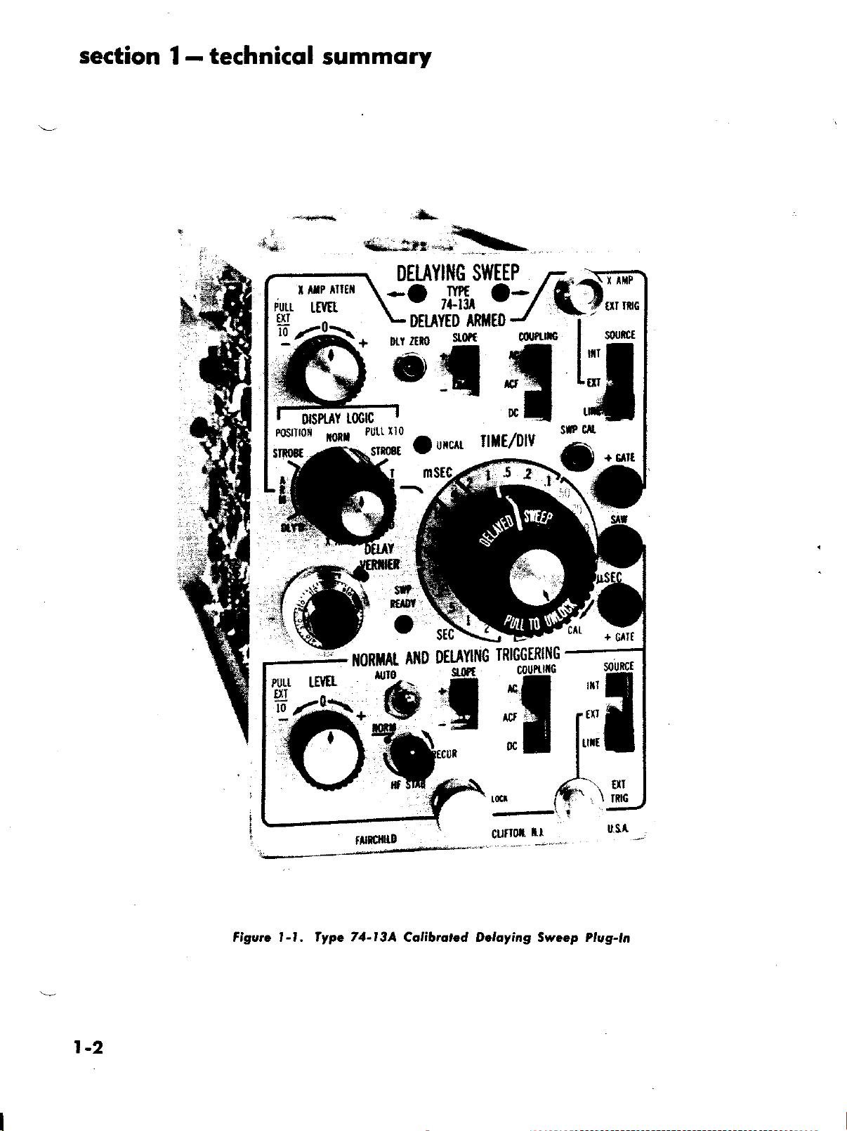
Figutc l-1. fype 74-l3A Calibtoled Deloyiag Sweep Plug-la
Page 5
SECTION
I
I.I. INTRODUCTION
IMPORTANT
MADE
MUST
THIS
entitled
instructions.
The
laying
Type
To
breviations
base delaying
BE
PLUG-IN
"First Time
Type ?4-ltA
Sweep
765/765IJ
simpli{y
is designed
Series of Transistorized
circuit
are employed
sweeps.
TECHNICAT
PTEASE
INITIAL
MODULE'
Dual
NOTE
ADJUSTMENTS
BEtr'ORE
See Paragraph
Operation"
Time
for use
description,
to describe
OPERATING
in Section 2
Calibrated
Base
the Fairchild
with
Oscilloscopes'
following
the
the
dual
2-l
for
tine
De-
ab-
SUiAXTARY
Abbrevictlon
NDT
DA
I.2. IECHNICAI
perfortrtatrce specificatiorr
The
rurodule
[ollows.
is
The NDT
Sweep
gered operation
sweep
delay
'l'he
Arrrred
sweep
oft trigger
An
quire<l
given in the
operation
starts
pick-ofi
DA sweep
operation
(NDT)
input trigger
to
5UIAf,IARY
Dercription
sweep
rettrs to
Delaying
and
(i.e.,
immediately
trigger
generates
which anns the
fire
the
is generated).
refers
(i.e.,
signal
DA sweep.
of
technical
strrnnlary
Normal
Trig'
delaYed
the
after the
to Delayed
the delaying
a delay
this
pick'
DA sweep).
is then
re-
plug-in
which
t-3
Page 6
section I
-technicol
summory
Cqlibruted Sweep
Colibroted lineqr
2 sec/div in 23 steps
Uncolibrqted
The
uncqlibrotcd ronge
ond
:econds full scqlel.
indicotor
Swecp
Sweep Ronge
Sweep
exf€nds
of uncolibrqted
Accuroty
t3% meorured over
lhc
CRT screen
Sweep
Swcep
Sweep
Goie Out
5ow
Other Conlrols
Ronge lndiaoto.
Push-pull
pendenl
Exponder
A
cqlibrqted Xl0 swecp
clutch knob
control of the NDT ond
omplifier will
center; extends ,ortesl
seconds/div,
rpeed3 fosier
for slower
tweeps. Neglect
Colibrotion
A front-ponel
vided
lhe
externol timc atondord
Two fronl-ponel
tive-going pulse
pedonce
lood impcdqnce
ond
direcily
swecp
Ponel
pcrmit
to
Moin Frome
(NDT
is 500
shunted by less thon
lo
bonono
of opproximolely
ihe NDT
l0K
thon
lnlernol
strobe inteniity
izes the
ovoid:
obrerving strobed
Sweep. Output impedonce
ohmr, ond lood impedonce
l00K ohms
controls
plug-in
hoving to reset
TIiAE BAsE
f,onge
iweep rqtes
Vernier
sYsTEM
(NDT
of l, 2,
conlrol
DA)
&
from 0.1
ond 5 requencc
providcs
of sweep rolcs between ronget
thc
2 sec/div ronge to 5 sec/div
The UNCAI lomp leryc!
expond
Exponder
ihon 200 nonoseconds/div
screwdrivcr
normolizotion
qnd
stondordizinq thc
yernier
or
the centered
permits
simultoncous
DA sweap rotes
cxponder in the X
lhc rweep
sweep role
occurocy is
the firlt
SWP CAt control i6
of thc
A DA)
bonono
of 2.5
ohms. For oplimum
should be
ground
ond i5 time-coincident
provides
iock
25 volts
shunied
optimize setiings
ond
strobe ironsiiion.
to the
CRT of the
iocks
yolts
greotcr
l5
ond is
by
eoch
nominql.
pf.
Gote
posifive
o
should
less
thon l5
ihe iniensity
disploy
modes
;lsec/div
o coniinuous
operotion
poriion
div
8
or inde-
obout screcn
lo l0 nono-
t5"L
ond
nqnosecondt
50
plug.in
rweeps to on
provide
o
Outpui im-
performonce,
thon lOOK
is rcfcrcnced
with the
.ow
coincident
is nominolly
greqte,
be
pl
of outomoli€
This normol-
Moin Frome
conirol
(50
oi
outpui
lor
+3
pro-
unit to
posi-
ohms
outpul
with
qnd
when
%
qn
of
SWEEP MODES
Normol
to
Deloyed-friggered
Deloyed-Armed
Deloyed
Single
X
Deloy Vernier
Sweep Operotion
Conveniionql
rweep disploy. lnlernolly
opplied trigger signols
circuil
Strobe
Deloying
rweep
disploy showing lhe deloyed
or o brightened reclor. The
immediotely
eroied
Deloying
os
o brightened rector, but
ened sector) i: ormed
initioted
The deloyed
rhe
deloying
brightening
position
Triggered
The
brightened
ofier the deloy
5trobe
sweep disploy showing ihe
by o sync
lrigger
sweep outomqticolly
sweep
of the sweep retrqce
or Deloyed Armed
scctor of the sirobe
ore exponded to full
LAYED modei.
off
the
of
sweep
dury
cycle
Sweep
The sinEle
sweep of the time
until ihe deloyed
The single
externql irigger
Level control
swiich
The
SWP
loyed
sweep
to
be irigge.ed
Amplilier
When the
X lnput
EXT setiing
lerobly
"
CAIIBRATED DEIAY IIME
A len-turn
on-icreen distonce
itort o, which
Automotic
deloying
(DA)
performonce
sweep
is lerminqied. Thir permits
iweep mode
bose lo oppeor
sweep
rweep moy
pelse,
or by switching the NDT trigger
READY
(for
D|SPIAY LOGIC
signols
indicotor is lit whenever
goie
multivibrqior
X-Y Disploys)
moy be opplied
of thc Trigger
Slope"
-
Control
precilion
lrom the
the
deloyed sweep is
the
drive
deloyed sweep
pick-off
dclqyed
the
by
deloyed
is terminqted.
scole in
proyision
in the DEIAYED
{DAl
be
by
either of the DE-
(NDT)
when
permits
is rescl
reormed
iurning
i: ormed
swirch ir
to X Amplifier
SOURCE switch
SYSIEM
poteniiometer
deloying sweep
or
exiernolly
NDT
lime bose
swcep
stqrtr
trigger
deloyed
sweep
gen-
is
sweep
(bright-
trigger ond
shuts ofl when
in
is mqdc
but one
prevent3
Thie
either STROBE
sweep disploys
for shut-
the deloyed
moximum
mode
driven
the
oi
icreen
or.eormed
q
with
single
the NDT Trigger
polority
the de-
ond reody
5et to X AA,IP,
vio
pre-
ond
determinei
either triggered
the
(NDTI
or ormed
l-4
Page 7
technicol
summory
section I
-
CAIIBIAIED OETAY lll
The DEIAY VERNIER
from zero to
o Deloy
Deloyed
Accurocy
lncrementol
trol is
Deloy Zero
Zero deloy i:
extreme
to
on
Deloy
Ronge
within
exlernol slondord
l0
Multiplier
TIME/DlV
occurocy
i0.25
Conlrol
occurocy, cny
from o minimum
20 seconds
IRIGGERING
(Scporole
fqciliiior for
HF Recur
A
unique high-frequency stobility switch
used to improve
hoying repetition
iloble synchronizqtion
to
beyond 50 Mc
lnternol Trigger
Signols
I Mc;
Type:
in Y covity. With
qdiurtment
trols will
will
trigger from 0.5 div of Y signol
from I div of Y signol up to |
76-01A, 76-02A,76-03
of the Trigger IEVEL
produce
o{ Y signol ol I Mc
30 Mc
(Concludedl
is
colibroied
control
in
coniunction
cqlibrqled con-
con be odiuslcd
losc orc
io reod
functioni
with ihe
ponel.
pqnel
proyid.dl
control
divisions.
when
coorrol
of the len-turn
%
odiustoble
or oll steps
ya
of
cqch fimc
SYSIEM
E
This
used
from the front
from the front
microsecond to more
SYSTEM
moy bc
counl down
rqte of 5 Mc
the HF STAB control set to RECUR,
o stoble
qnd
qnd
lock-in
grcqlcr.
of signols
or
of I cm dcflection
0
qnd
76-08 Modules
qnd
HF
STAB con-
disploy
2 divisions o{ Y signol
with
0.2 diviiion
of signolt
provides
lt
Mc wiih
lhon
up
For
ot
qs
io
Trigger
Slope
positive
Selection
Line,
of
or Externol triggering
or
[ine Trigger
Line frequency
poloriiy
with
the Trig LEVEL
Ext
frig lnput lmpedonce
I megohm
AC
Coupling
High-poss
cycles
DC
Coupling
Direcf
coupling is
tivity when
mointoin lhe iniliol reference
wiih respect
setting; ond lo ovoid trigger
rondom repelilion role lrigger signqls
ACF
Differentiqled
vided to
modulotion; low-frequency
Signols should rise
pois
the LF reject filter
Automolic
Triggering
Visible bose line
no
iignql
signol
of
q
trigger signol switches the sweep to the
mode immediotely
triggering con be selected in
ond the iriggering
conlrol
shunted by
filter
very slow
to the CRT scole oi o
trigger input;
reiect hum
inpui,
l0
cps
40
with
low-frequency
provided
woveforms
ond low-frequency
or foll in lesr
oll sweep ronges when there is
on
The rweep free runs uniil o lrigger
to l0
Mc
negotive
slopes on lnternol,
is
ovoilqble
poinl
mqy
(nominol)
pf
be :hifted
cutoff ol 80
to optimize trigger 3ensi-
ore opplied; to
porition
point
high-poss
of lhe lroce
given
trigger level
voriolions
{ilter is
omplitudc
cutoff nominolly l0
thon 100
is
opplied. Applicorion of
triggcrcd .
either
du€
pro-
prsec
lo
Kc.
to
Extcrnol frigger
0.5 volt
the sweep; I volt
to l0
(Xl)
peok-to-peok
Trigger
Mc.
or dc coupling ore included.
,rol sei io RECUR,
produce
control
lOV input
Externol Trigger
Some frequency limits
'10,1
ing
Trigger
A ronge
ground
will
ot I Mc
(XlOl
qttenuqtor
copobility to
Level
of i'l 0 volis
on exiernol lriggering
lrom dc to I Mc will trigger
peok-to-peok
leveling, slope ieleciion
odiusiment
o stoble
provided
is
will trigger the
Wirh the HF STAB con-
the Trigger
of
disploy
os
exiernql
to
extend
:t100 volts dc
(nominol)
with
with
trigger
the
dc level.
respeci io
sweep
qnd qc
LEVEI
0.2V to
Xl; o
HORIZONTAI.
DEFTECTION
Bondwidth
Direct
Coupled: DC to
Copqcitively Coupled: Low-frequency
cycles
Sensitivity
(XI0
Exponsionl
2 Mc; down 3 db ot 2 Mc
EXT/XI Ronge: 0.1 voli/div
EXT/XI0 Rongc: I volt/div
X
Vernier, A tert-io-one
vided in the horizontol
tion chonnel io exiend the inpul
signol ronge to l0 volts/div
Seniitivity
(Xl
Exponsion)
Reduces oll obove
sensitivities by l0:l
scon)
sYsTEM
cutoff is
ottenuotor is
(Restricied
80
pro-
deflec-
I
-5
Page 8

rection
I
-technicol
rummoty
\--.
HOIIZO TAf DEfLECIION
lnPut lmP'don"
lnFul
I mcAohm
Connaclot
rhuntod
x A lp froni-ponal
usc ol
dirployr.
lhc
horizonlql
(DA
EXT TRIG connccto.
purporel
SYStEil
pf
by 40
conna€ror
dcfloclion
(Concludodl
(nominqll
providcd
i!
omplifior for
tGrvc, thit duql to
parmil
ro
X'Y
X Poritlonins \
A fronr-ponal
tioning
rwcap to withio
Boom
Porillon lndltoloru
Two indicqlor lonpr
qlad
whan
ii ir
control
of th.
X lnput rignol
th.
op.roior or lo
poritioncd
p.rmitr
iwo
divirion!
orc
off lhc rcrccn
coqrrc
or
of
locotrd
the
dircciion
ond finc
ponion
ony
rcrqGn
caniar
on th. tront
tho
of
poai-
oI
pqnrl
Lcom
th.
I
I
t-6
Page 9
sEcTroN
2
OPERATING
2.I. FIRST IIME OPERATION
(Figurrt
If this is the ftrst tinte these
then certain
Used,
For instructions,
Recalibration
nrake
The
tbllowing adiustnrents.
the
NDT
Sweep
DA
Swecp
Strobe
Pqitcrn
Deloy Zero Adiurimcnt
Dcloy Col Adiurtncnt
following illusrations are
operator in beconring
Sweep Plug-ins.
Figures
Figure 2-2
Figure
Figure
Figure
Figure
Unless otherwise
Y Amplifler Plug-in module is inserted in the
&
2-l
2-lb
2-3a
2-3b
2-4a
2-4b
(left-hand side) and the Type
Plug-in unit
side) of the Main Frame.
know that
We
with your new
deavor,
you may set up the insrument
in calibrator
various conrols on
2.2.
SWEEP
Two trigger
Sweep plug-ins. Each Time
own separate triggering
To obtain a stable
sistently
cycles of the input waveform. If
to occur
of occurrence of the input waveform, the
pattern will be traced
start at the same time relative to recurring
at random
to 2-41
2-l
have
rrrust be lnade.
Maintenance and
Porogrcph
5-9
5-r0
5-l I
5-17
5-t I
5-19
designed to aid
reler
and
Adiuctmcnt
lcngth
Swecp
Col
lcngth
lniensity
Correclion
plug-ins
initial adjusttncnts
Section 5,
to
the paragraph indicated,
to
qnd
tamiliar with the
a
Type 74-13.4,
and Connectors
Type
74-13A,
Type 74.134, Triggered
Display
Type
74-13,{,
Display
Type
74-13A,
Type
74-13A,
designated, it is presumed that
Function of Controls
Normal Display
Strobe
Delayed
Armed Strobe Display
Armed Delayed Display
Triggered
74-l3A
Time Base
is inserted in the X cavity (right-hand
you
are anxious
instrumenl To aid
demonstrate the effects
to
signal
the display.
IRIGGEIING
get acquainted
to
you in this
using the
circuits are built into the
Base is provided with
facility.
display, the sweep
the
at a rate unrelated to
or
at a difterent point on the
out
must con-
sweep
been
ever
and
the
Delaying
Y cavity
en-
built'
of the
Delaying
its
is allowed
the rate
displayed
INSTRUCTIONS
screen each time the sweep
the waveform to
drift
ligible. The sweep theretbre
input
signal, or by sonre
tinre relationship to
poses, the starting of each
the screen
rnay be callerl
lollowing instructions tell
the proper
triggering signal
2.3. TRIGGEI SOURCE
lnlernol
o.
For rrrost applications,
by the
the signal amplitude
To
signal,
ternal triggering
Y input signal.
obtain
riggering
set the TriSger
is convenient
gering connections
are obtained
in rnost applications.
b. Extemql
Sornetirrres
it is advantageous
with an external signal.
pecialty useful where signals
lrom several difierent
With external
reurains constant in amplitude
a
possible to observe the shaping
signal
oscilloscope triggering
AIso, time
forms at difierent
in an external
For example,
rived from
tirrre relationship and phase of the
in the circuit are cornpared
1>oint
by the displayed waveform.
When a
it is possible to observe and
able,
jitter
of
trigger input signal. This is not
is
sweep
signal
scope
trace
show the proper time relationship
displayed signals. To
ternal triggering
nray
to display the
External triggering should also be used
amplifier
riggering, the
and phase relationships
points in the circuit
if
the external
ihe waveform at
stable,
external
the displayed waveform with respect
triggered internally.
b€ used to externally
module in
signal
runs. This
the screen or to
across
must be triggered
signal which
the input signal.
horizontal
"triggering
yorr how to select and use
for various applications.
SELECTION
the sweep
The only
be sufficient
of the
SOURCE switch
are required.
Exrcrnal
are
places
triggering
circuit without
controls
the input to a circuit,
triggering signal
entire signal.
the
obtain a
must have an amplitude
will
bears a
For
waveform across
the sweep." The
may be triggered
requirement
to triSSer
sweep from
either
be
unintel-
by the
present
is that
the sweeP'
the input
cause
to INT.
since no external
Satisfactory
to rigger
triggering
going to
within an
signal usually
shape. Thus,
and
and amplification
results
the sweeP
is es-
be sampled
instrument.
resetdng the
for each observation.
between
riggering signal
waveforms at each
to the
the wave-
can be seen.
is de-
inPut
signal
is avail-
accurarcly measure
to the
possible when
A
trigger
preceding the
trigger the oscillo-
with
a dual-
AlTernate mode to
between
stable display, the ex-
the two
fixed
Pur-
In-
trig-
it is
of a
the
the
of
at
2-l
Page 10
section
2
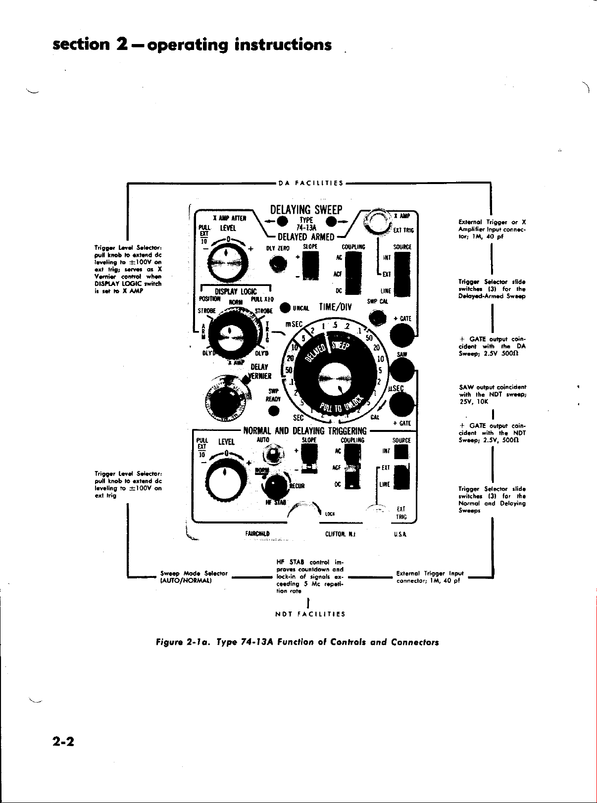
operoting instructions
-
DA
\
FACITIII€S
Tdg!f,. Lr.l S.l.d.r,
lrcb io .rt nd dc
FrI
l.tdini t
.rr fig;
Y.rrb
OlSttAY IOCIC tril.n
T.i99.r L.v.l S.lGror:
pel
le.ling io
+100V
..w..
co.rrol
t.ob to .
a
q!
Yh.o
.nd
l00Y on
DEI.AYIl{G
*,'frfl'
H
--o--
Yo
LDtuYEo
-O_
oll
I
r6flu
t(I
tl-l
nttri0
#'t
ltoflItt
dG
At{D DtuYilrG
rUIO
,S'
SWEEP
,Ih
nnuEo
J
''/'
l 5 2:
TimffitfiG
stP cll
C
uit
IlI'
ul
s0utct
I
.l
cllt
s0ufltt
t
I
Ill
TRIG
me
E*.rnol lrigs.r
Ahpli6.r
Irifff,
rit h.'
D.@-Ard.d
+
GAIE
.id.it
Sw..9, 2.5V 500l)
SAW o{lput
with rh.
25V, l0(
+
GA'IE ouiFl,t .oin-
wiih
.id.nl
Sw..p, 2.5V. 500()
Trigg.r
.wiiGh6
No.nql o.d D.loring
o. X
Input.on...-
.lidt
S.l.cl,o.
for lh.
13)
5*..p
otpol <oi.-
*ilh rh. DA
coin.id.nt
NDT 3w..p;
I
rh. NDT
did.
S.l..tor
lor
13,
lhc
2-2
il;tffhi'li*-
Figvrc
2-lo. fype 74-l3A Funclion ol
'
clnoi. i., u.st
Xt STAI .onhol im-
vs .&nld6vn dnd
s:I";,if:*#
rion .ot
NDT FACILITIES
I
Controk ond
::'.'i::,:J"ff:iJ?'
Connecrort
_l
Page 11
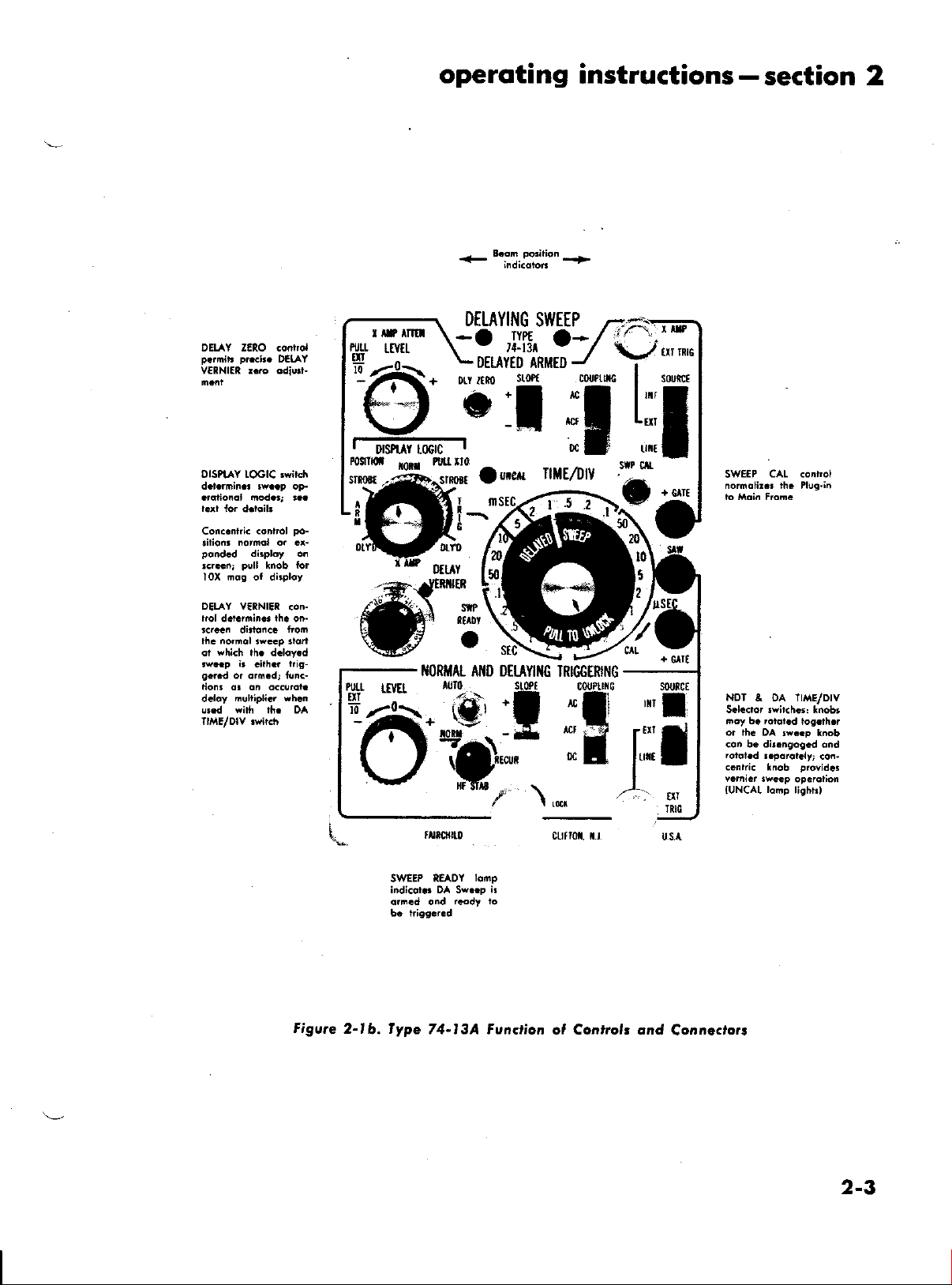
operoting
BEm mrilion
instructions-section
2
DELAY ZERO GontrcI
prci..
p.rmit!
VERNIEI r..o odiurl-
DISPiAY LOGIC aw ch
d.t.rhin.. 3w..p oF-
.,olionol modG, !..
Con..n[i.
{lionr
pond.d
!.ran;
Iox oos of dirploy
DELAY VERNIEI
l.ol
d.t
rc.... dirlonc.
no'nol
th.
which
ot
,wcp ir .ilh.. l ig-
g.r.d
lioh. dr on a..ordl.
d€loy
!r.d
DEIAY
po-
.onrol
normol o, .t-
dhplo, o.
pull
tnob
riin.. lh.
6r om.dr tun.-
Eultipli.r vh.n
eilh
con-
frcm
rwep ,orr
rh. dcloy.d
lh. DA
on-
DE[AYlliG SWEEP
?#'ffiI" \-?J.h"..?-/
-':-f\.
;lffu'*#"7*",*
11=
-t
uI
s0uict
nt6
-l
g#iitli
O-T;:
LI
I
CAL <onlrol
SIVEEP
+
€llt
60r
ffi
PU(l
Int!
txT
'id
Dtut
TIORIIAL AITD DEI.AYII{G
IRIGGTRII{O
sorJtct
J*:
nornolir.! rh. Pl!9.ir
NOr
& OA Trl4E/DrV
S.l..ror !rit.h.s: lnobt
noy b.
rctoi.d l,og.th.r
or th€
DA tw..p lnob
con b. di!.ngog.d
rot.l.d
!.porot iy;
c.nric knob
Y.mi.r 3wccp
lomp
IUNCAL
ond
con-
provid.r
opcrolion
lightt)
Figvte
SWEEP
indi.ot.. DA Swnp ir
orF.d ond
2-lb. fype
lo'np
READY
r.odI to
74-l3A Fvnctioa
ftrfru f,r
o, Controls ond
Cornecrort
2-3
Page 12
section 2-operoting instructions
least 0.5 volt,
time relationship
external
signal to the
ger SOURCE
Line
c.
lf the
ship to the
triggered
Trigger
coupling mode with LINE Trigger Source.
IRIGGER
2-4.
peak-to-yeak (l mc)
to the disptayed
signal
pattern
SOURCE
lbr triggering the sweep, connect
TRIG
EXT
switch to EXT.
on
power-line frequency, the sweep may
by this
signal.
COUPTING SEIECIION
connector
display bears a frxed time relation-
To accoruplish this, set the
switch
to LINE. Always use dc
bear
and
signal.
and set the Trig-
6xed
a
To use an
the
o. AC Coupling
Selection of
by setting the COUPLING switch to AC. This rlode
is provided with a high-pass filter that has a low-fre-
quency cutoff noruinally at 80 cycles, This feature
prevents
tern vertically and using internal triggering. In the
AC ruode, triggering
ponents o[ the
tioning of
selected to provirle the desired tlisplay via
the AC triggering rnode is accomplished
erratic
triggering when positioning the pat-
is
unaftected by the rlc com-
triggering
the
race.
signal or
The
by
vertical posi-
the
triggering level can
use of
the
Tlig LEVEL control.
When using the
switch
point
is
set
the Wovef ol n for a given Trig LEVEL
on
control setting regardless
Note:
AC coupling
calibrator signal or lquare
cycles,
severely integrates
rnended
fornrs
lbre discrinrinated against by the low-frequency
rnay be
lbr these
DC Coupling
b.
The DC
ruode is especially useful
which change very slowly and which are
ot the AC position (80 cps). llecause of
network tinre
randonr repetition
stably
in the DC rnode, This urocle pennits excellent
triggerirrg on all tyJrs of waveforrns and
AC rrrode, the Trigger COUPLING
to AC. The trace always
the vertical positioning.
o[
triggering on the line-frequency
wave signals less than
erratic
since the 80-cycle cutoft
the trigger. DC coupling
signals.
starts at
the sarne
is reconr-
for viewing wave-
there-
cutoft
the coupling
constant in the AC rnode, signals having
rates
are solnetirnes
viewed
is rnost useful
ruore
l(X)
6lter
in the lbllowing applications:
l. For optinrizing trigger sensitivity or operation
low-[re<lrrency
when
For maintaining the initial reference position of
2.
the uace with
signals
respect
are applie<t:
to the CRT scale at a
given
TRIG LEVEL control setting when on Internal
source: anrl
3. For avoirling rigger point variatiorrs
dorrr repetition rate
triggering signals.
rlue to ran-
be
be
When
switch is
trace
always starts at
a given
setting of the Trig LEVEL control
using the
set to
DC mode, the Trigger
DC. When using internal
the sarne
point
on
COUPLING
source, the
Scale
the
for
regardless
of the vertical positioning.
c. ACF Coupling
The ACF
rnode
is a
special
high-frequency lbrrn
the AC urode and is used to reject low-freqr.rency
components in the triggering signal. Use AC trigger-
ing
unless low-trequency rejection is required. Trigger-
ing
signals with
lbr exarrrple
sweep circrrits
ACF mode
hace
mod,e,
ACF ruo<le
of the
gering.
Signals nrust have
l0 g,sec
tirne
signals are to
ing.
Note that the Type
plug-ins
pernrits
the
ACF electronic
Occasionally
the calibrator
when the ACF ruode is
uill asmre
plug-in
ond,
two channels
when it is
using internol tt igger
prevents
when using the ACt'
provided
are
triggering from one channel
it is required
fre<luency
the difterence in positioning
froru interfering
be
switch
corrrponents
signal,
ttiggeting
stable
set up
rise or
<tisplayed, use external trigger-
76-08
fo|
fall
mode.
and
with a selector
below l0
rnay
not initiate the
Also,
use<l.
the
lxnn
alte|nate
source.
with
Thus the
stable trig-
times faster than
If slower dual
multi-trace
other
switch which
Kc,
the
d.ual-
sueep
level
only. Therefore
mode no
to
longer applies.
obtain stable trigger-
ing fronr a corrrplex high-frequency wave[ornr that
contains
querrcy cornponents. In such
and line pickup rnay rnake it difficult to
stable
rlo(le, thereby
<lesirecl corrrponents. The low-frequency corrponents
are blocked fronr the riggering circuit while the high-
frequency triggering
the
respects, the ACF
,A.C rnode.
unclesirable low-trequency noise or line-fre-
cases,
the additional
display. Il this occurs, select
elinrinating
waveforu
stable triggering that
is
[iggering
the ACF
the efiects
is
of
passed to produce
required. In all other
rnode is identical
noise
obtain
triggering
these un.
to the
2-5. IRIGGEI SLOPE SEIECIION
When
sweep is riggered on the rising
the Trigger
SLOPE
switch
is
positive slope of
or
set
to
+,
the
the excitation signal. When the Trigger SLOPE
switch is set to
negative
or
2.6. IRIGGER
The Trig LEVEL control
specific voltage which
ceed betore
switch is set to rhe
Trig LEVEL conrol
sweep consistently
the sweep is triggered
-,
slope o[ the excitation
IEVET
SEIECTION
perurits selection
the triggering signal must
the sweep fires.
When the Trigger SLOPE
position,
+
urakes it possible to trigger
on the positive slope
the falling
on
signal.
o[ a
ex-
adjustment of the
the
of the ex-
of
a
2-4
Page 13
Mltflal
Io obl,oin
.r&p. t.l
p.rforn
operqt:ng
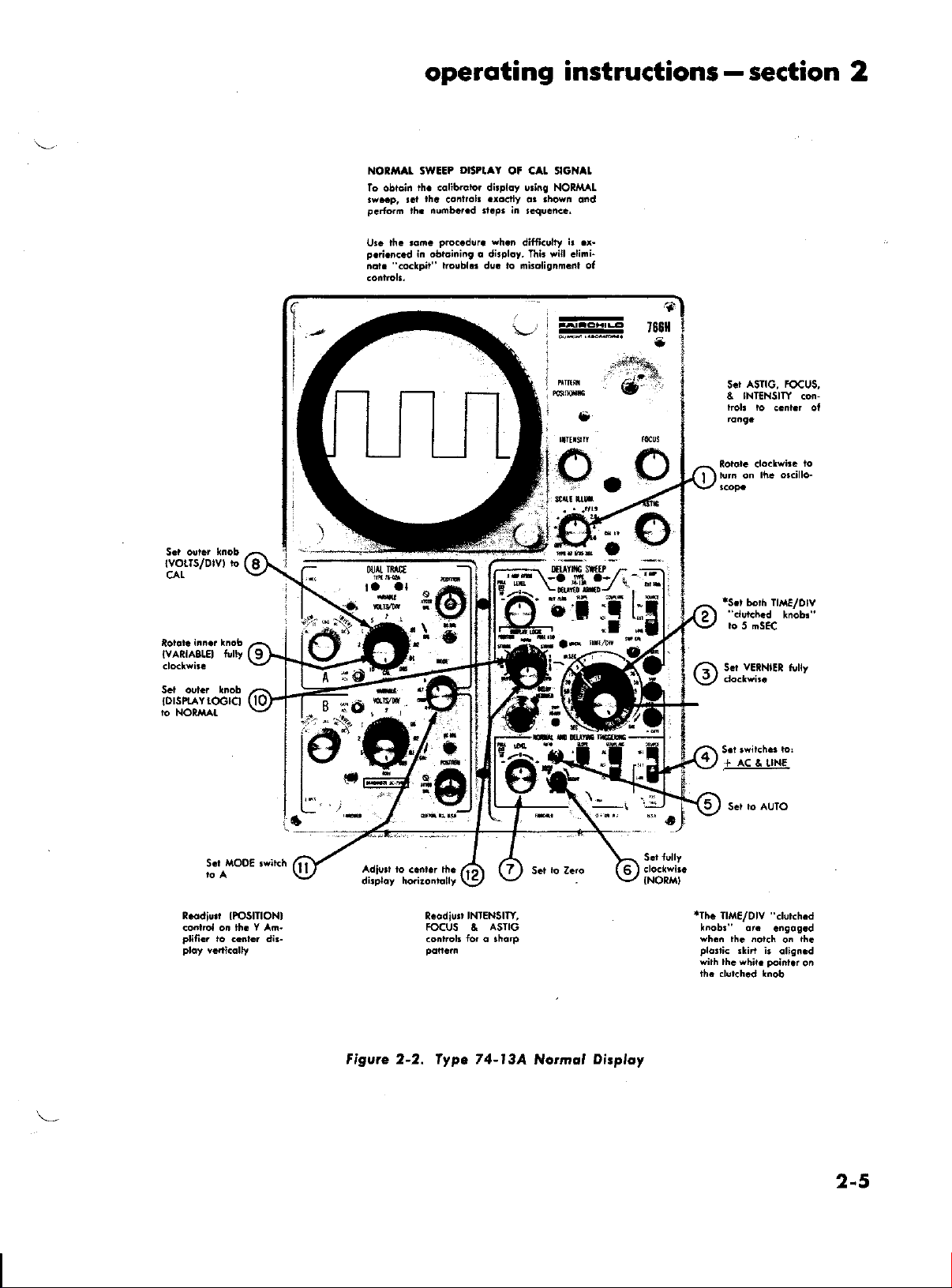
DrSPtaY
swEEP
th. .qlib.otor dirploy u!i.g NOR^IAL
th.
conlrok
nu6b.r.d tt.p. in
ih.
ot cat stclt t
.ro.rt
instructions-section
o. rhorr ond
r€qu.nc..
2
lvoLTs/Dtv,
CAL
NAnlASLEl
tully
lhc ro,n.
Ul.
p.i.n<.d
".o.lp,r"
not.
proc.dur.
in obtoining o ditpl6y. Thir will .lini-
l6!b1.. ds. l,o nhoiignm.nl ol
'h.n
difii.ulry
L
.r-
?
t
I
I
,60fl
e
ASIIG, TOCUS,
S.t
NIINSIIY
&
kolt ro
con-
ccnl.r of
o
a-
"I
o
iT
to
S.r
5 nSEC
vElNlEl
tully
to
O{&
ta
IME
al
ffi*a
$fa
6'i;t'
tDrsPraYroclcl
l,o
NORli L
R.odiu,
co.lrcl on th. Y An-
plific.
io c..t . di3-
IPOSIIIONI
INIENSITY,
R.adiu3,
FOCUS A
ASIIG
Figvre 2-2. fype 74-l3A
Normol
Dirploy
",,
.
S.t rully
{NORM}
+ actUNE
IIME/O|V
'Ihc
knoba or.
wh..
th. .ot.h
pl6ri<
rlirt ir
with lh.
yhir.
"clukh.d
.nsos.d
o.
qlig..d
point.r
th.
on
2-5
Page 14

section
2
operoting
-
instructions
S.r DETAY VtRNlEl
diol ,o 0 ond
th. OELAY ZEIO .on-
trol uDtil th.
iu.i
rh. l.fr hond rid. ot
th. i.o... Thir
otion colibroLr
DEIAY YEtNlEl
Sd
IOGIC
Tdgg.r.d
3i.ob.
di.opp.or
DIS?taY
rh.
ayiich
5TnO3E
odiu.t
op.r-
ih.
diol
IR]GGIRID
ii
Thi!
d conll.lorion
figu..2-2. S.t lh. .ont.ok .ro.fy o.
thorn ond
on
ro
p..fon
of lh. iniliol r.tup oI
th. .u6b.r!d
n.Ps in
STTO3E
,ighr
AND
6SEC!. Ih.
ll
DEI.AYED
S.i 08 Y
diol to a.
ot th. dirploy b.rw..n
4 o.d 6 dlviion. ol
ih. .tqd ot
nol Sw..p
b,ighl.r ihon
Th. on@nr
rrigg.rins rienal cnnl th. D.iot.d lr..p
di..c{y by ,h. ,.nine ol
rkiri ond
,v..p rcr. ot 5 nse/Div
NlEl
20 millit..ondi. Th. oba. opplio onlt
lrigg.r.d
o,
DEL
diol ..ting oa a div
op.r.rio..l nod.
vEtNlEl
ponion
Ih.
rh. NoF
.hould b.
ift. r..t
NOIE
d.l.y o.c!ri.t lrci
rh. NDI IIME/D|V .rikh
Y VElNlEt.diol. h rhit
i. mulripli.d
. .olib.or.d d.loy rim. ol
ri.ldins
i.
u,.d.
rh.
OEL
rh.
lplorti.
rh. NOT
Y vEt-
d.lor.d-
oFplicorion of
ri.rt, i! indi<ot d
inrronc.,
ri.
by
rlDn ,h.
Figure 2-3o. fype 74-l3A friggered
inr ro 5 nstlc
m6inm
-
fir
Strobe Disploy
2-6
Page 15
operoting
instructions
section
-
2
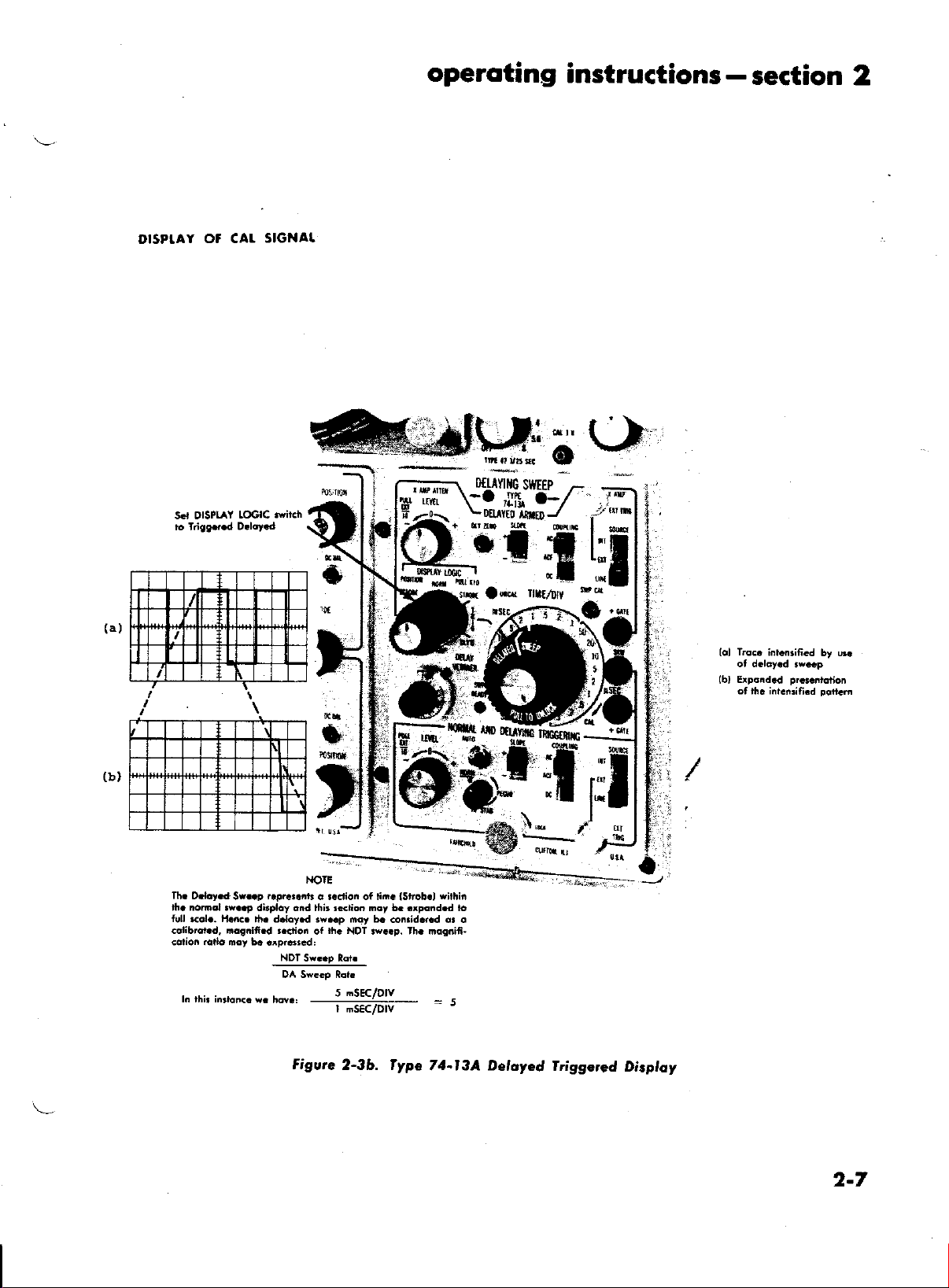
DISPTAY O' CAL
SIGNAL
Lo..
{ol
(b)
i.i..rifi.d
Erpand.d
ot rh. iii.tuifi.d
by 6.
pr.i.6iction
Doti.n
Th.
O.loy.d
|ft. nom.t r*..,
fu[
..o1..
colibrot d, no!.ifi.d r.dio.
<otion .ado my 5.
r. thr rnr6n<. w.
r.pr...nb
Sr..p
dirploy cnd thit l*lio. moy b. .xp.nd.d to
ll,!c.
rh. d.loy.d
.'pr6r.d.
NDT
DA Sw.Gp [ot
h@.:
Figwe
a r.ction ot lii.
p..p
not b.
ih.
of
NDT 3y..p. Ih. nordifi-
Sw..p lot
5 nSEC/D|V
---------------
r
dEc/Dtv
2-3b. fypc
*ithin
lstrob.l
co.rid.r.d or o
--
5
-
71-l3A Deloyed
tfiggered
Disploy
2-7
Page 16
section
2
-operoting
instructions
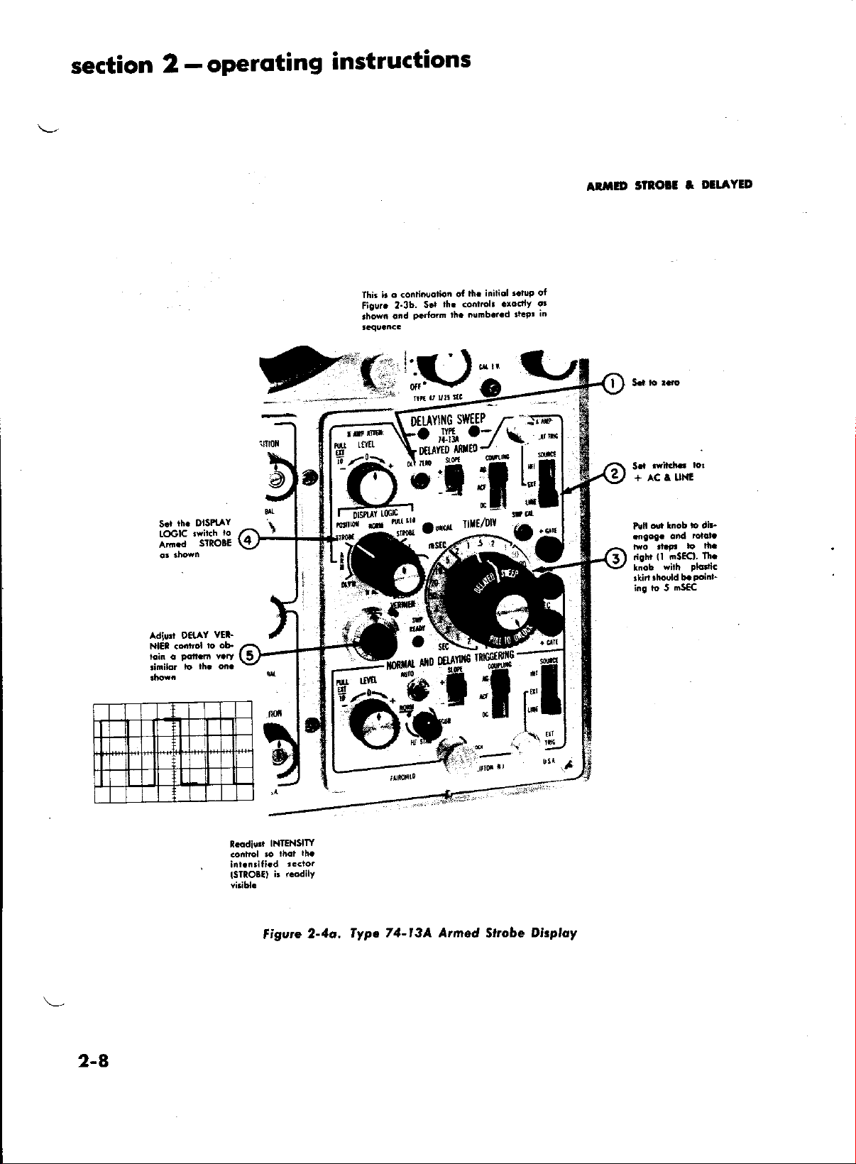
thi. ir
tigur.
,han
o conti.l)otion
2-3b.
ond
of
rlt. <onlrcl..6dlY
S.l
p.rforn
lh.
iniliol
lh.
nunb.r.d
r.t!P oI
tt.tr
DI]AYED
atntD
or
In
$to!t
+ ac t
I
LlNl
DlsPtlY
rh.
s.r
twiich
IOGIC
SIXO3E
Ann.d
Adiurt OeAY
Nl€t .6ntrol
VEI-
l,o ob.
to
n.odili
tSTlOlO
INIENSITY
r..dily
i'
figvte
2-1a,
fypc 74-l3A
Armed
Slrcbe
Disploy
,isht
ll
ing io 5
SECI.
mSEC
n'.
2-8
Page 17
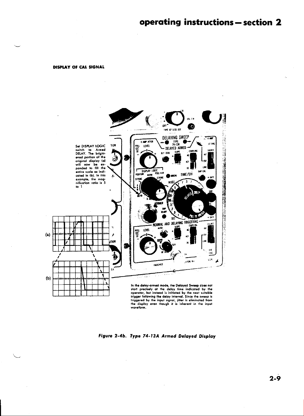
DIgPI.AY Oi CAI SIGNAL
LOGIC
OISPLAY
S.r
th. bighn
DELAY.
operoting
@u
instructions
section 2
-
(a)
Figvre
2-4b.
t:;
ln rh.
d.loy-orn.d
pr..ir.ly
.tort
opdqtor, but inn.6d i. inifior.d by th. n.rt ruilqbl.
ki99d lollo*iig th. d.lny int.Ml.
trigg.r.d by ih. inpul
iha
di5ploy !v.n
lype 74-l3A Armed
mod., th.
iic
ot
iholgh
O.loy.d Sy..p do.,
d.ldy riD. indi.at d by th.
lignol,
r i.
iirt
inhlr.nl in th. inpui
it i.
Deloyed
lh. rw..p
Sin(.
.liminot d
froi
Dizploy
I
;
noi
i!
2-9
Page 18
section
2
operoting
-
instructions
citation
switch set
LEVEL control
consistently
signal.
ntay be
pulling
tion.
2.7.
signal.
Normal
extendecl
the
SWEEP OPEIATIONAT MODES
Conversely,
to the
position,
-
makes
it
on the negative
trigger level
to
I00 volts
:t
Trigger LEVEL
with the
adjustruent
possible
to rigger the sweep
slope ol
range
on external
knob into EXT/10
Trigger SLOPE
the
is
tl0
o. lntroduction
When
the start
period
application of the triggering waveform.
plished through
Base and the
NDT Time Base is
delay while
horizontal
duratiou o[ the
TIME/DIV
tings.
The delayed sweep ltature of this instrument
be
increase
magnification of a selected portion
sweep, accurate tirne rueasurerrrents,
neasureDlens
to pick
scan or
b. Sweep Rongc lndirotor:
The NDT TIME/DIV
indicator window nrounted
TIME/DIV
is identified
knob of
Delayed
permits
to adjust both
Delayed
rotated indepe[dently
NDT sweep rate.
c. No.mql Swo.p
lvhen
NIAL,
ing is derived
line. External
EXT TRIG connector.
d. Triggered
\Vhen
gered
using the Delaying Sweep
thg horizontal
of
of from
I
simultaneous use
sweep can be delayed {or
rnicrosecoud
DA Tirne Base. In this application,
used to provide the accurate
the DA
sweep at the
and the
employed
in a nuruber
its versatility.
of wavefornr
off and display any desired line
to check pulse-time
switch
as the Delayed Sweep knob. Turning the
latter
the
Sweep tiure duration.
the outer'knob to
Su'eep range knob nray
Tiure Base provides a normal
end of the delay
sweep delay is
DELAY VERNIER control set-
o[ special applications to
Such applicatiorrs include
jitrer.
rnodulation.
switch
on
is urounted
will also
engage
sweep ranges
to sweep rates faster than the
Dirploy
the DISPLAY
only the NDT
fronr the displayed
signals uray
Strobe Dirpldy
the
DISPLAY
STROBE, and
LOGIC
Tirne Base is displayed.
be applied
Reter
LOGIC
the Delayed TINIETDIV
Base Plug-in,
Tirne
to
seconds after
20
This
of the
controlled by the NDT
an
of
and accurate
Also, it is possible
of
is provided with
a plastic skirt; the DA
top
on
perurit
A
sirrrultaneously, or the
switch is set to NOR-
this
of
control
push-pull
the
skirted knob
be declutched and
signal internalty
to the lower
to Figure
switch
2-2.
is
set to Trig-
the Trig
of
excitation
volts. This
source by
posi-
is
accom-
NDT
Time
time
period.
a television
The
rnay
high
undelayed
skirt and
of
clutch
Trigger-
switch
the
an
the
or
is set
for a higher
DIV
switch, a portion
(See
Figures
brightene<t
Delayed
the
Delayed
uray
be positioued
VERNIER
adjusted with
that
the
ol the latter
sible to inch,rde
in the
brightened
The arnount
a
tion
of the triggering
Sweep
is pemritted
setting
DELAY
occrrt iurrrre<liatcly
1;rliod.
tlre
This rrrocle
Delaye<l-Triggerecl
of operatiotr
tinuously
tirne
arrd waveform
The Delayett
the Normal
brighteuing
STROBE positions.
e. Deloyed
When
gered
DELAYED,
play
in the STROBE
scale. See Figures
The amourrt
NDT sweep rate
magnification
,
IIaEnifrcation rittio
For exarnple, if
to I mSEC, and
to I
pSEC,
uragnified horizontally
LOGIC
tion.
Normal
This
DELAYED
switch
Autonratic provision is rnade
Sweep when
pernrits
f. Deloyed-Armed
If
the display is set for
the delayed
indicated
applied to the DA
sweep rate than the
o[ the sweep tnay be
2-3a and
portion
Sweep
Sweep
control.
start o[ the
control.
(Strobe) irrclicates
ancl the
length of the
cluration. The
left
or
The length
thc
Delaye(l TINIE/DIV
stobe is not afiected by
Using these two
any portion
or strobed area.
of delay occurring
wavefomr
to run, is determine<l
of the
VERNIER control.
NDI' TINIE/DIV
at the en<[
frortr uow
su'eep rrrotle.
that
pernlits the
variable
delay
jitter
Sweep
Su'ec1t
of
the
Triggered
the DISPLAY
autouratically
is
ternrinated.
sweep retrace in
Dirploy
LOGIC
the brighterred
position is
2-3b ancl 2-4b.
of nragnification is
to rhe
ratio ulay be
Norrnal Sweep Rate
-
)elayed Sweep Rate (TirrreTDiv)
the NDT TINIE/DIV
the Delayed TINIE/DIV switch is set
the brightened portion
1000 tirnes when the DISPLAY
is
set to the Triggered DELAYED posi-
the Delayed Sweep is terurinated.
rnaximurn
N'TODE.
duty-cycle perforrrrance in the
-
Operoiion
sweep does not
delaved period
trigger circuit.
until
NDT TINIE/
brightened.
2-4a.) The start
the start of the
strobe
start
of the stroh
right
with
the DELAY
ol the strobe nray
corrtrol. Note
controls,
of the display
fronr
the applica-
unril the
switch ancl
The
Detayed
of the
on will lrc
operator
tirrres for uraking
tneasurements.
Sweep
preset delay
referre<l
It
is thc ruo<le
to select con-
shtrts
This prevents
either
switch is set to Trig-
section
now
Delayed Sweep
expresse<l:
of the dis-
expancled to full
the
ratio of the
(Tirne/Div)
switch
of the swcep is
for
shutofi of
Delayecl-Arnred
start at the
operation,
en([ of the
a triggering
This triggering prrlse
of the
inclicates
the
setting
is
it
pos-
waveform
Delayed
by the
the
will
to as
accurate
off when
of the
rate. The
is
set
the
pulse is
be
2-to
Page 19
operoting
instructions
section
-
2
nlay be
either the input
ot an externally-derived
irrg Source,
in the sanre lnanner
antt DELAYED
Arrrre<t mode
not start
DELAY VERNIER
setting, but instead
triggering following
ruro<le
.{rured urode
2-4b.
The arrtted clelayed
to be conrirruously variable.
lrc
used whenever
cunrulatiye
sweep
g.
Auto
sweep ranges'when
sweep free
cies between
cycles
nal
immediately
mode.
lng
srgnal ls
running
,The
when
will
always be
to
the
operation,
Coupling,
Slope, and Level nray be selected
as for
triggere<l operation.
of operation,
lxecisely
at rhe delay rirne indicated by the
and NDT
is initiated by
the indicated delay interval. 1'his
frorl now on will be
of sweep operation. See Figrrres
tirne
jittel
and the delaye(l magnified
Automotic
triggering
runs
is
applied-
thus
-providing
mode
autornatic
doing
-oscilloscope.
set the
the signal to be displayed has ac-
between the
NDT
Swrep
provides
there
undl
a trigger
l0
cycles and
The application
switches
stable sync.
removed,
after
the
a delay
NDT
equipment
visible
with
To
obtain automatic
Sweep Mode
AUTO position.
h.
HF lecurront
Stable synchronization
nals
can.be
is
operadng in
tion
-is-
switch
improves
ing
repetition
stable
to
beyond
i.
Single-Swcop
Sirrgle-sweep
nloves
sweep to view a varying
overlappd
displays
r'hen
ever,
input
shape,
best accomplished
selected by
in the
the count
synchronization
50
but one
arrd rrnintelligible
being
it is rlesirecl
signal which
or tinle, the instruurent rnay
Sweep
the
recurrent
setting
HF
RECUR
down
rates
of
5
of
Mc.
Operotion
oyleration irrlers
sroke rrntil reset. Using
wavelorrrr u'ould
suprinrposed on
to view a
continually varies in
wavefon to the oscilloscope
niggering
the conventional STROBE
signal. The
In
the
trigger-
Dclayecl-
the Delayed Sweep does
TINIE/DIV control
next
the
referrecl to as the Delayed-
<lisplay does
The Arnred nrode
srritable
2-4a ancl
not appear
shoul<l
start o[ the nornral
section.
visible
a
is no
approximately
base
line
signal input.
signal with
on all
The
frequen-
l0 6ega-
of the trigger
the sweep
sweep
of about
sweep
testing
or without
very
of
when
mode.
rhe Sweep
position.
and lock.in
Mc
or
signals of I
to
the tiiggered
When the
reverts ro
trigger-
the free-
I second"
mode is
since a reference
high
greater.
very
a signal
NDT
toggle
Recurrent
switch
frequency
the NDT
Mode
Use of this
of signals hav-
Ii provides
cm deflection
applied
uselul
trace
sweep
sweep
operi-
[%gle
switih
that the tirrre base
a reptitive
result in an
<lisplay caused by
one another. How-
single <lisplay of an
be
many
amplitude,
set up for
sig-
sig-
O
single-sweep presentation.
one
stroke of the
ation
elinlinates the
tiple traces
or recorded
Single-sweep
Delayecl
the Delaye(l SweeP is
Sweep
sweep at
and enables the display to be vie\^'ed and/
clearly.
operation
in
the Delayed
the NDT Delayiug Sweep,
to trigger the NDT Delaying
1:lishe<l
Sweep LEVEL control to
by
connector. The Delayecl Sweep will
uDtil
sweep will occur
are locked oua until
words,
tinre
travel, the beam will
The
the
trigger signal arrives.
2-8.
thc sweel) nray be
nrantrally by rotating the NDT Delaying
a signal
applietl
triBger signal
a
after
a single trace will sweel) across the
the sweeP is triggere<l and at the
'l'o
rearrrr the sweep, procee<l as instructed
will
swecp
screen arrd
SWEEP
then
is
arrne<l ready to
EXPANDEN
When the POSITION control
exl.rarrderl
o[ l0 about thc screen center. Thus,
exparrsiorr
segrrcnt
TION control
o[ the
tlte POSITION coutrol.
of a desire<l segrnent of the
inierest
of
exparr<led
to rhe screen center with the POSI-
and pull out this control. Any portion
<lisplay nray
Thus, by corlrnandilg but
a tirne,
overlapping
is
single sweep
cause<l
by the
obtained by using the
Arrred rlo<te. Since
arnred
to
the
by a trigger derived froru
the
arnlirrg procctlure
Sweel:. This is accom-
both
extrernes
the ND-I-
EXT TRIG
electrically
or
renrain anrretl
arrives
which further incorning
to fire
the sweeP. One
circuit is rearnre<l. In
screen each
triggers
end
rest ofi
retrace to the left hand si<[e
screen.
fire rvhen
the rrext
knob is pulled
horizontally
It
observecl by adjusting
bv a factor
to achieve
trace, set
an
oper-
nrul-
input
other
of its
above.
out,
Xl0
that
lVheu the irrstrurrrent is set up tbr Xl0 expansion
of
the sweep,
the
sweep rate
indicated by the
setting
of the TINIE/DIV control rrrust be divided by l0 to
obtain
one division. For
is
rnilliseconds,
slon.
2.9.
the Main Frarrre
panel
the actual tinre required
exanrple,
set to l0 nrSEC, the actual tirue
<livkterl by 10, or I millisecond per divi-
SWEEP CATIBRATION ADJUSTTAENT
Whenever
thc
-I'irrre
Base Plug-in is removed
and inserted in another, rhe
screwdriver
SWP CAL control lrrust be
This procetlure is necessary
ence in
'I'irne
Y
be
plate voltages
deflection sensitivity
proprly
tweeD the plug-in
as lbllows:
dellection plate
Base
unit is switche<l
cavity
of the sarne Main Frame,
necessary
since the difierence in average deflection
between modules
noruralize
the gain between channels
unit aml the Main Frarrre, proceed
sensitivities. In addition, if
of the carhode-ray tube. To
for
the sl)ot to nove
it the TIME/DIV control
per
division is l0
from
front-
reset.
to conrpensate for
from the X cavity
readjustment will
affects the
difier-
the
to the
over-all
or be-
is
oI
2-tt
Page 20
section
l.
Set up
CAL
signal. Allow
Figure
trol for
(60-cycle
for 5 cycles
use 0.5
for
2-2.)
2. Set TINIE/DIV
3. Adjust SWP
NOTE:
msec/div sweep and
2 cycles of the calibrator display.
2
-operoting
the itrstrurnent
a warmup
C.{L front-parrel
precisely 6 cvcles
line)
iu l0 divisions.
For
5O-cycle line, adjust SWP
of the calibrator
2-r0. x-Y otsPt AYs
KEEP INTENSITY
Screerr <larrrage
bearn resting
When <lesiring
another
signal to INPUT A connecror
the
the
to shorv
rneasurernents,
sinrilar
Set
(not the internal
X signal to X AMP
Delayirrg Sweep module.
sweep
signal relationship.
the DISPL.{Y LOGIC
carr rcsrrlt
at orre point
to view
signal generator plots, Lissajous phase
curve trace
DA Trigger SOURCE
SLOPE
X.4,\IP
display
2.I I.
is
+ GATE.
into
shor.rld
thau l5
other
vierv the
on the
pulse
the leading
no signal
rneasured
counter.
neasure
oscilloscope in
the tiure duration
DIV
operator
.
\-
the
ar-e thrrs
switch
ATTEN con[ols
the
on
GAIE
A positive
available
The gate amplitude
irupedance
an
be gteater
pf. This
devices in
output of
oscilloscope.
Use
of
the
generators
edge of the pulse
clelay is incorporared
1'he
perio<l of the
extrerrrely
Since the pcl io(l
of total
anrl
the V,\RI.\BLE
to rlisplav
entire
srveep. Tirling
readily obtailable.
ro
+.
screen.
OUIPUT
gate coincident
on a front-panel
of 500
than
positive
order to
such <levices
gate
ourput in conjuncrion
will perrnit
sweep tinre, it is
conjrrncrion
of input signals.
the rvavetbrn
for nonnal display
switch
tirne
to l0
l5 minr.rtes.
of
mSEC.
screwdriver con-
o[ the calibrator
display. For 400-cycle line,
adjust
CAUIION
SWP
LOW
[rotl too irrterrse
on the screen.
one voltage plotted
tinre base)
on the Y Plug-in and
(green) BNC connector
X-Y displays nray be
itrforruation and
swirch to X ALIP,
switch
Adjust the
Posirivc
accurately
to EXT, and the
VOLTS/DIV
to
obtain an aPpropriate
r.ith
the sweep
BNC
counectoi labeled
is
volts
2.5
ohtrs and load irnpedance
l00K
ohrns shunred by
pulse nray be
achieve
usecl to trigger
sufficient delav to
conrpletely
with triggered
rhe
instrutnenr to display
waveforrn
in
the Y
gate
n)ay of course,
with an
of the
gate outpnt is
possible
u'ith
a corrnter to
Use
of rhe TIttE/
controls
accuLacies
rtill perruit
to lrc nreasurecl
of I
instructions
of the
(See
display
CAL conrol
CAL control
a
against
used
other
the
DA
and
olrrpr,rt
less
be
a direct
cligitize
the
over
in lOi
Y
on
zontal
Step I by rhe I'IME/DIV
cau
urrit
CAL). To
repetition
ceed as follows:
apply the
nourinal
displlyecl
even tholrgh
Arnplifier.
electronic
to use this
l)arr
2.I2.
SAWIOOIH
A
front-panel
positive-going
tude.
The
saw
volts
oI ground
sweeP.
The
sawtooth voltage nlay be
tlelayed
as a tirne base
sawtooth
ance
trrore
ator
2.I3.
scope
tirrre
brated
CAL). Use
nreasure
of interest
val, proceecl
the clisplay
activities,
output
to
ground
than
15 pf. Voltage
probe is
TI'IIE
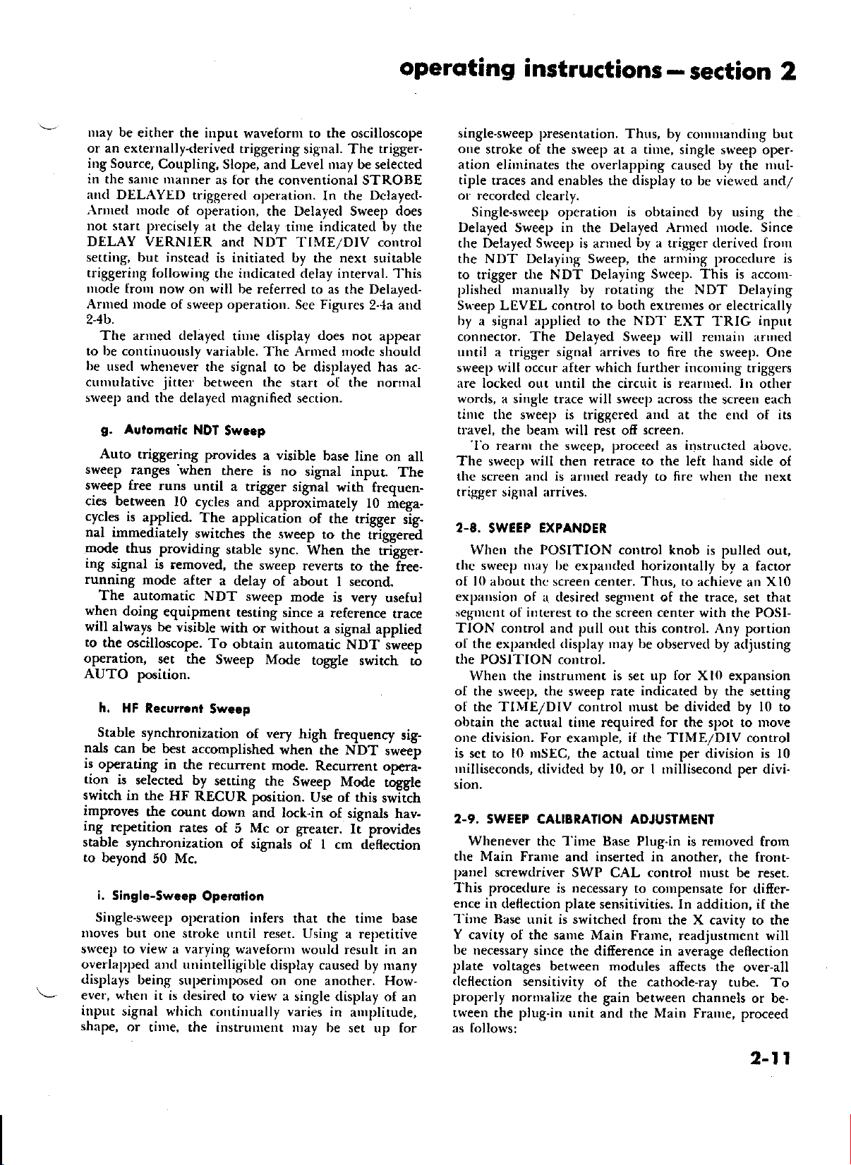
o.
How to lvloke
UsinE the
,{ny
horizontal
can be
when
the tinre-base
sweep
of
rhe
on the
l.
Using
the calibrated
(listance
whose time
MEASUREMENIS
as follorvs:
2. llultiply
the
tirne
interval.
b. How to find
Uring the
The
repetition rate
be expressed
OUTPUT
connector
saw
ol approxirrrately
outpur
and is
is referenced
time coincident
controlling
for associatecl
should not be loaded
less
of
than l00K
recorutrendecl.
Elopred firne
CRT
Scqle
distance
used
to represent a precise
(TINIE/DMernier
this fearure
elapsetl tinre
clisplay.
in divisions between
interval
the horizorrtal dirnension
See Figrrre
Repetition
CIT Scqle
or frequency tbr
as the nultrber
of tinre (TINIE/DMernier
use the
rate
ELAPSED
oscilloscope for rueasuring
or frequency
TIME EOUALS:
T
I
x
E
s
Figwe
2-5.
Elopsed fime
labeled
SAW provides
25
within
with
used
an X-Y plotter,
analog
take-oft
on the
circuits are
equiprlent.
oh[rs shunted
through
Meosuremenl:
screen
set up for cali-
control
1>enrrits
benveen
To rrreasrrre
scale, nreasure
yott to
the clesired point
the rinre inter-
that portion
you
wish
conrrol
setting
2-5,
Rote
of cycles or pulses per
Frequency
of
periodic signals
control set to
of perioclic
,Ueossrement
volrs
arnpli-
minui
the NDT
for initiating
or actint
The
by an
irnped-
by no
an attenu-
the
of
oscillo-
interval
set to
accrrrately
the hori-
to find.
obtained in
to
obtain
the
signals,
pro-
a
3
of
of
2-12
Page 21
operoting
instructions-section
2
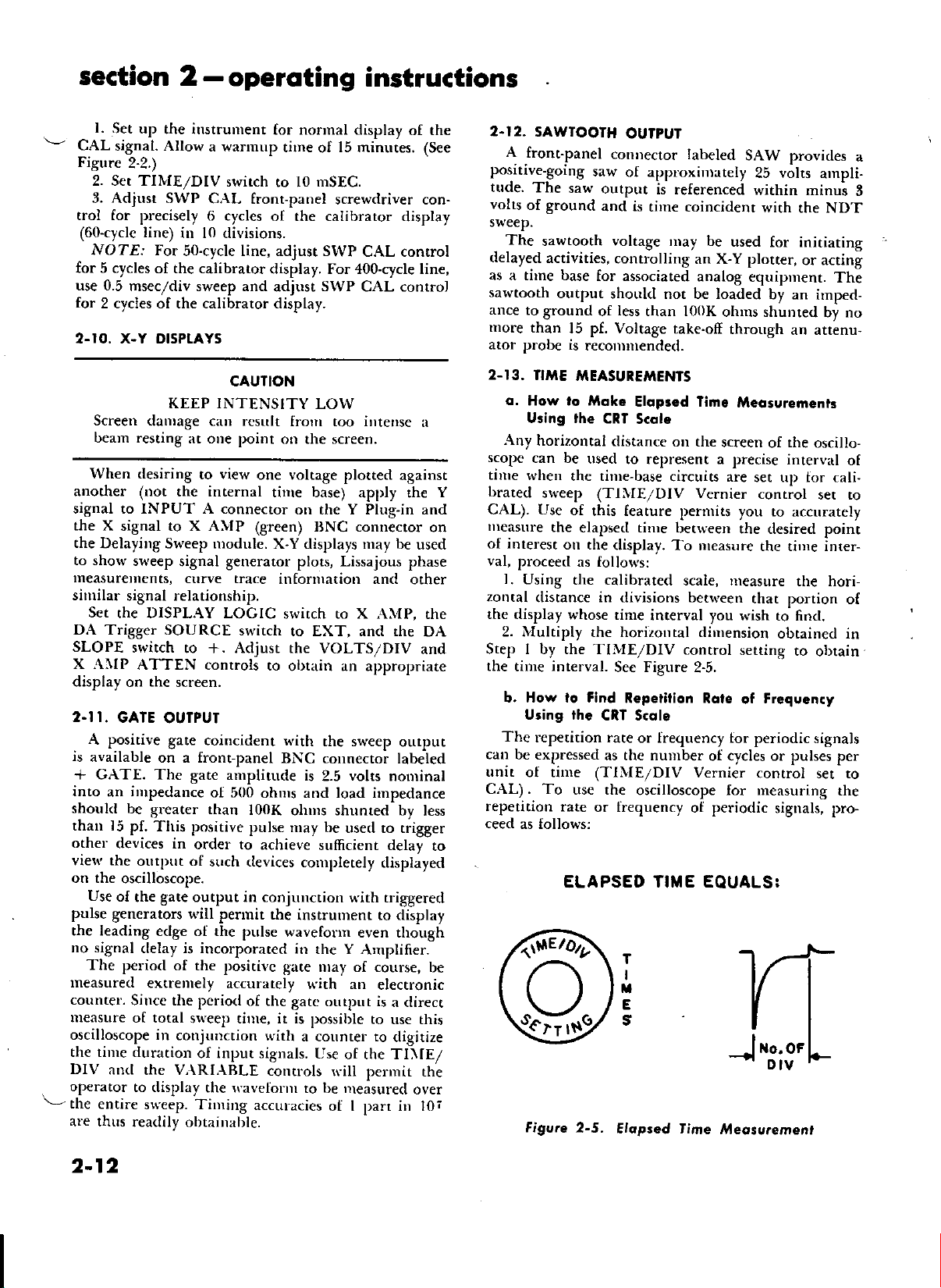
l. Using the calibrated
clistance
display under observation.
2.
Step I by the TINIE/DIV
3. Take the reciprocal
Step
quotient is the rlesirerl
cycles per
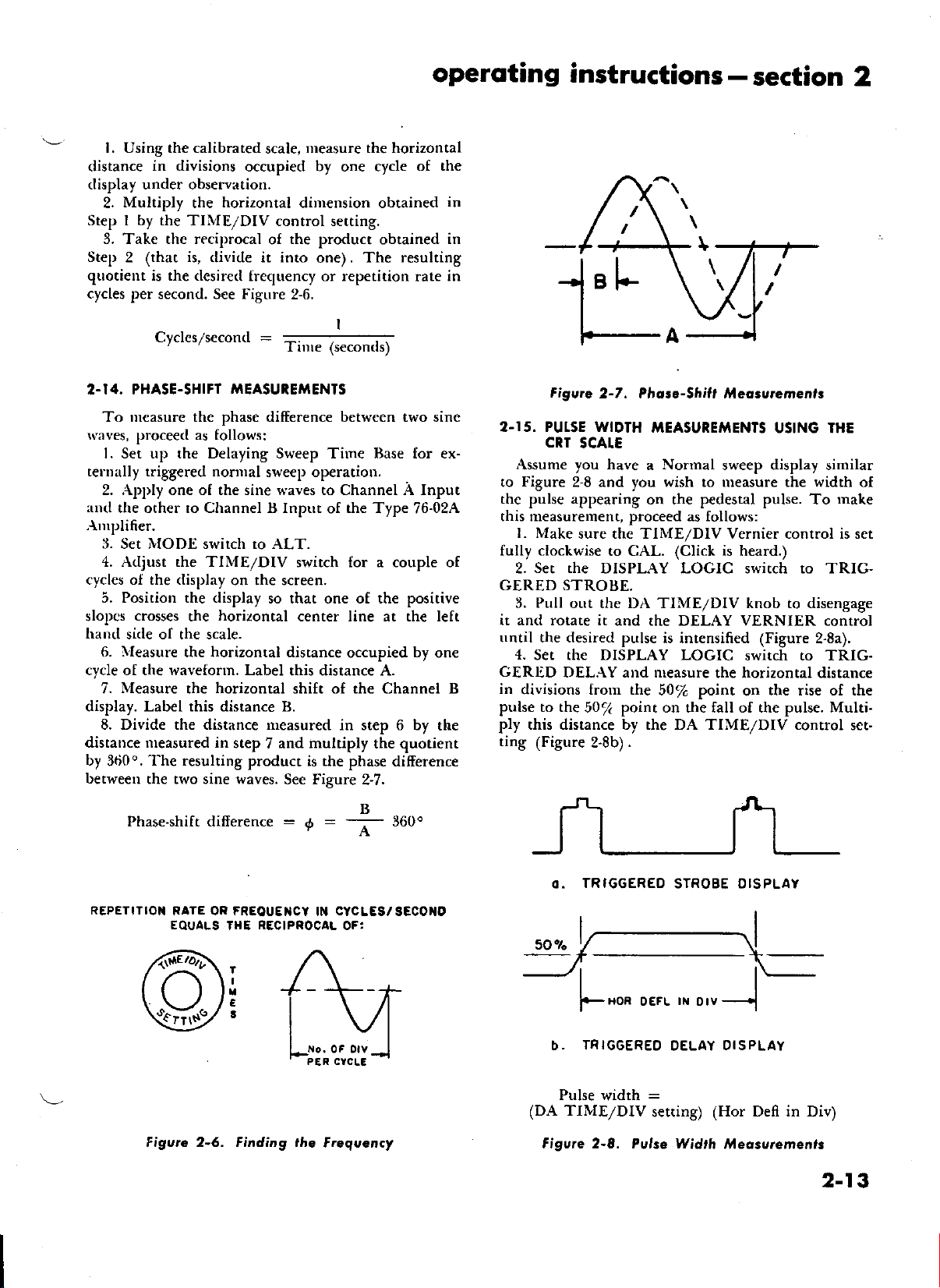
2.I4. PHASE.SHIFT
To rueasure the
l.aves, ploceed as follows:
in divisions
Multiply
2 (that
the
is,
second. See Figure
Cycles/secon([
occupied by one cycle
horizontal
divitle it into
[ret;uency or reperirion rate in
TTEASUIEMENTS
phase
measure the horizontal
scale,
dirrrension obtained
control setting.
the product
of
one). The
2-6.
=
Tinre (seconrls)
difierence between two sine
obtained
resulting
l. Set up the Delaying Sweep Tirne Base for ex-
telrrally triggered norrnal
2. .\pply one o[ the sine llaves to Channel A Input
arr<l
the other to Channel B Input
.{nrplifier.
3. S€t NTODE switch to ALT.
4. Adjust the TINIE/DIV
cycles oI the
5. Position the display
slopcs
harrrl
sirle o[ the scale.
lleasure
6.
cycle o[ the wavefonn. Label
Nleasure
7.
display. Label this distance B.
8. Divide the distance neasured
distance rneasured in
by
3ti0o.
between
(lisplay
crosses
The resulting
the two sine waves.
horizontal
the
the horizontal distance
horizontal
the
sweep operatiou.
of
switch lor a couple of
on the screen.
so that
one
center line at rhe left
this distance A.
shift of the Channel B
in step 6 by
step
product is the phase
multiply
7 and
See Figure
the Type
of the positive
occupied
the quotient
difference
2-7.
of the
76-02.4
by
one
the
in
in
11
Figurc
2.I5. PUTSE WIDTH
CRT
Assume you have
Figure
to
the pulse appearing
this measurement, proceed as follows:
l. Make
fully clockwise
Set the
2.
GERED STROBE.
Pull
3.
it and rotate it
until the desired pulse
4.
Set the DISPLAY LOGIC
GERTD
in
divisions trom the
pulse
to the
ply
this distance by the DA TIME/DIV conftol
ting (Figure
2-7. Phore-5hift /l{eosuremenrr
IAEASUREMENTS
SCALE
Nonnal
a
and you wish to ureasure the width
2-8
on the pedestal
sure the TINIE/DIV Vernier control is set
to CAL. (Click
DISPLAY LOGIC switch to TRIG-
or"rt the DA TIME/DIV knob to disengage
and the DELAY VERNIER control
is intensified (Figure
DEL.\Y and nreasure
50/o
point
50/<
2.8b).
on the fall of the pulse. Multi-
sweep display similar
is
the horizontal distance
point
USING THE
pulse.
heard.)
switch to TRIG-
the rise of the
on
To
2-8a).
of
make
set-
phase.shift
REPETITIOII
Figvrc 2-5. Finding ihe
difierence
RATE OR FREOUE]ICY
EOUALS IHE RECIPROCAL OF:
T
I
E
3
:
=
a
f
CYCLES/SECOIO
IN
oF otv
Frcquency
loo.
TRIGGEREO
o.
l---------.l
i,--------\l
50%
IFHoR
=F
(DA TINIE/DIV
TRIGGEREO
b.
Pulse
width
Figvre 2-8. Pulse
STROBE DIS PLAY
rl{
oEFL
Otv
OELAY
:
setting)
(Hor Defl in
rl,lidth
---.1
PLAY
OI S
rl,leossremenls
Div)
2-13
Page 22
section 2
operoting instructions
-
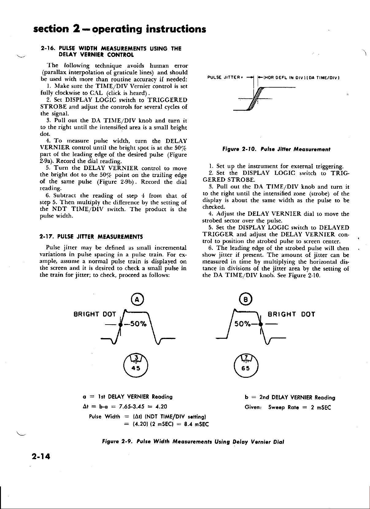
2.16. PUI.sE WIDTH
DEIAY
1'he follorving
(parallax interpoladon
be used
l. Nlake
fully clockn'ise
Set DISPLAY
2.
STROBE
the signal.
Pull
3.
to the right
dot.
4. To
VERNIER control
palt
of the leading
Record
2-9a).
5. Turn the
the bright dot
of the same pulse
reading,
6. Subtract the
step 5. Then
VENNIEI
technique ayoids hurnan error
rvith more
sr.rre the TINIE/DIV
than routine accuracy if needed:
to CAL
LOGIC switch to TRIGGERED
and acljust
out the
the
DA TINIE/DIV knob and turn it
until the intensined
measure pulse
until the bright
edge of
the dial
reading.
DELAY
to the
50/c
(Figure
reading
nultiply
the NDT TINIE/DIV
pulse width.
2.I7. PUTSE
Pulse
variations
aurple, assuure
the
screen and it is desired
the train for
JITTER MEASUREXIENTS
jitter
rnay be defrned as
in pulse
jitter;
spacing in a pulse train. For
normal
a
to
check,
IIEASUREiIENTS
CONTROT
graticule lines) and should
of
Vernier control
(click is heard).
controls for several cycles
area
USING
is
a small bright
'HE
is
width, turn the DELAY
is
spot
the desired pulse
VERNIER control
point
on the trailing
2-9b). Record the
of step
the difierence by the setting of
switch. The product is
small
pulse train is displayed
to check a small pulse in
proceed
ar the
+ frour
incremental
as follows:
50%
(Figure
move
to
edge
dial
that of
the
set
ex-
on
of
PULSE JITTER,
Figurc 2-lO. Pulte
l. Set up the instrument for external
Set the
2.
GERED STROBE.
3. Pull out the DA
to
the right until
display
checked.
4. Adjust
strobed sector over the pulse.
Set the
5.
DISPLAY LOGIC
is about the same width as the pulse to be
the DELAY VERNIER
DISPLAY LOGIC
(HOR
0EFL
rX
0rV
) I
OA TrME/o|V
Jiltq /Ueqrureman,
triggering.
switch to TRIG-
TIME/DIV knob and turn it
intensified
the
zone (strobe) of the
dial to
switch to DELAYED
move
TRIGGER and adjust the DELAY VERNIER
trol to position
6. The leading
jitter
show
rneasured in
tance in
the DA TIIVIE/DIV
divisions of the
the suobed
edge of the strobed pulse
if present.
time by rnultiplying
knob. See Figure
pulse
to
The amount
the horizontal dis-
jitter
area by
screen center.
will then
jitter
of
2-10.
can be
the serting
)
I
the
con-
of
2-14
BRIGHT
q
=
Ai
=
Pelse
lst DEIAY VERNIER Reodins
:7.65-3.15
b-q
width
Figure 2-9. Puke Widrh /UeoturemeDrr
:
:
lAr)
11.201
=
(NDT
(2
1.2O
TIME/D|v
mSECI
:
8.4 mSEC
sefting)
:
b
2nd
Given:
Using Deloy Vemier
HT
DEIAY
Sweep Rote
VERNIER Reoding
Diol
DOT
=
2 mSEC
Page 23
sEcTloN
3
3-1. TNTXODUCTTON
(Figurer
To
sirnplify circuit description, functional block
and waveform
LOGIC switch settings
Figure
Figure
Figure
Figure
Figure
Figure ii-5. Siurplified
Figure
Figure
Figure
Figure
Figure
Figure
tigure
The tirning
points
Iationship.
waveform
nrentioned
interrelation
ation. It is
the rear
circuit
3-2.
in the
The circuit
description.
TRIGGER
(Figures
o, Normol
Since the input o[ the Norrral
ing
circuit (NDT)
(DA) tlig^gcl circuit,
3-l ro 3- 12)
timing diagrarns at various DISPLAY
are provided as follows:
3-la. NDT Trigger
Block
Diagram
3-lb. DA Trigger
Diagrarn
3-2. Nornral Sweep Nlode,
Block Diagrarn
3-3. Tirning Diagrarn
Display
3-4. Triggered
Block Diagram
-
Triggered
3-6. Delaye<l Triggered
Block Diagram
3-7. Simplified Timing
Delayed-Triggered
3-8. Arnred
Sirnplified
3-9.
Strobe Nlode, Functional
Block
Diagrarn
layed-Armed
3-10. Delayed-Armed
Block Diagram
3-ll. Simplifrecl
tayed-Almed
3-12. Horizontal
Functional
diagraurs
circuit and in
In
addition, a
is provided.
description
illustrations.
of circuits
also recomnrendecl
of the manual
CIRCUIT DEsCRIPTION
3-lo ond
ond Deloying Triggering
is sinrilar
show waveforms
Eurphasis
rather rhan
be
3-l b)
only the NDT
CIRCUIT
Circuit Functional
Circuit, Functional Block
Functional
{or Nonnal Sweep
Strobe Nlode, Functional
Tirrring
Timing Diagram
Tirning
Dellection
capsule description
wilt be
reterred
to rhat of Delayed Armed
Diagratr for
Strobe Display
Nlode, Functional
Diagram for
Display
Strobe Display
Nfode,
Display
Block Diagram
proper
Functional
Diagram for
Amplifier,
relative tilne re-
keyed to
is pla(ed
on derail
that the
and Delaying
schematici
to in following
circuit will
for De-
at critical
of each
the afore-
on the
o[ oper-
trigger-
DESCRIPTION
De-
at
the
be
discussed in detail.
rlescription
The input to the
rtay
Trigger
(l)
tained from
of the X Inpur circuit.
be selected fronr
SOURCE switch as follows:
In EXT or EXT/10 position, the signal is
an external source through the EXT
TRIG front-panel
(2) in INT position,
Y
Plug-in unit; and
in
(3)
one sirlc o[ the 6.5 VAC heater circuit.
,4, choice of AC,
by
the Irigger
tion, the trigger
consisting
low-frequency
cutofi
high-pass filter
DC position,
the triggering
arrrplifier.
series with
protect
input
Preselves
LINE position,
oI C8203, C8205,
cutoft
is raised to l0
now has R8204
the high-pass frlters
signat is
The RC network,
the g-rid
the input circuit from damage
voltage. Shunt capacitor
the high-lrequency
The negative pulse
arnplifier
signal
the
going portion
this,
desired polarity
For positive-going
the
nection is
the
adjustable
R8222.
riggering
switch.
Thc
trigger
transformer
applied to
oI the delaying
The TRIG
diode
BAL
V8202
adjustrnent
u,hen
occurs
at the input. However, it
during
sweep
of the excitation
the Trigger
grid
opposite grid is
of
made
V8201,
by means
This conuol
point fbr
output from
shaper
trigger
adjustrnenr R8234,
through
Q8202
18201.
series coupling
sweep gate multivibrator.
SENS
at its optimum
of the Trig
the Trigger
Re[er to paragraph
uigger
connector;
ACF, or DC coupling
COUPLING switch. In
signal is applied
of 80 cycles. The low-frequency
Kc
of
when
only
either a
SLOPE switch is used
of the riggering
signals, connection
and for negative-going
to the grid
connected to
of the
is used to
all settings
V8201
which drives
The resulting
adjustnrent
trtnnel
diode
SLOPE
3-8 for a
amplifier
of three
one
the signal is derived from
V8201 ancl V8202,
sources
via
the
ob-
the
the signal is tapped from
is provided
the AC posi-
to a high-pass frlter
and R8207, providing a
in
the ACF position
shunting R8207. In the
are disconnected
applied directly to the rigger
R8206
V8201
signal component.
at rhe outprrt
chere is a positive-going
positive-going
signal. To accomplish
and C8202, in
or V8202,
due to
C8202
across R8206
the
o{
is desirable to
or negative-
the
and
and
serves to
excessive
rigger
start
to select the
signal.
of V8202. In each
a dc bias
Trig LEVEL
select rhe level
of the
Trigger SLOPE
V8202
or
diode
sensitivity.
sets the level
CR820l,
LEVEL
srvitch
is apptied
the trigger
negative trigger
CR8203 to
R8229,
control is
is
set from
is made
signals, con-
coupling
rhe
sets
The
of V8201
so that no
required
case,
source,
control
of the
to a
rhe base
tunnel
TRIG
and
re-
pius
to
ro
is
3-t
Page 24
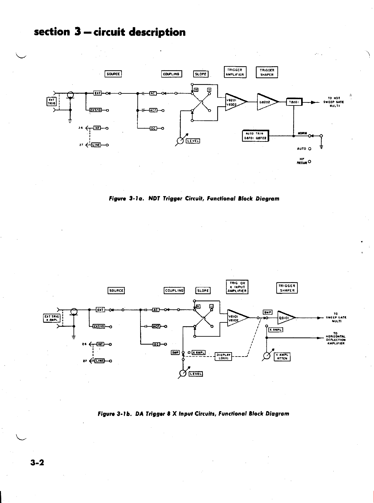
section
3
-circuit
Isor"c.l F.orr-l
description
rnrccra
I
laveur,:a
I I rn,cm I
I ls,^era
I
Figvn
3-lo. NDt friggot Citcuit, Funclional
Fo,r".
",c'l
F.o"rl
Elock Diogtam
3-2
Figurc 3- l b.
DA
fdggcr
8 X tnptt
., Functionol Block
Citcui
Diogrom
Page 25

circuit description-section
3
made
minus slopes or vice versa. This adjustment
when the Trig LEVEL
Automoti. friggering
b.
When
AUTO,
comes
l0
the
synchronization of the desired input
the Sweep
the trigger circuit is
activattd. Application
cps to l0 Mc switches the sweep immediately to
hig8ered
mode.
control
Mode
This technique
is set to Zero.
&BBle switch
ungrounded and
a trigger
of
signal.
is
is
signal
insures
The
set
be-
from
stable
auto
rigger multivibrator reverc to its natural mode in
about I second after the discontinuance
ger
excitation
ence trace will appear on the screen even
absence of an input signal.
3-3. CIRCUIT
(Figuror
o. Drloying Swecp
input triggering signal
The
transistor
of
CR8205. The dc
and
Q8207,
receiving a negative
Diode CR8203 and
sequent
retrace are conrpletetl. ln the qLriescent
is
conclucting and
positive gate while
lbrward
the
CR8205 serves as a
which couples the
circuit
initiates the sweep. CR8203 also serves as
impedance diode
the sweep gate urultivibrator. After the bistable
vibrator has been triggered, the
the saw
CR8204 condrrcts anrl resets the
aud
to the sweep gate
Q8207,
signal. Consequently, a horizontal refer-
DESCRIPTION OF
qnd
3-2
3-31
NORMAI SWEEP
Gots i ultivibrotor
is
applied
Q8206,
initiates the fbruration oI
through series-coupling
corrple(l bistable
multivibrator
trigger fronr the shaPer circuit.
the lockout circuit
triggering signals until after
Q8207
Q8207
sweep
is at cutoft.
tbrnrs a negative gate during
interval.
low capacitance coupling
negative trigger fronr the shaper
rnultivibrator
to <lecouple
reaches full screen cleflection, turn-off diocle
the trigBer
swecp
nrultivibrator
which then clanrps
the
of the trig-
in
to the
the
sweep
hold ofi sub-
the sweep and
state,
Q8206
which
a high back-
shaper
runs up. When
saw.
base
diode
Q8206
after
.Q8206
tbrnx a
(liode
flips and
frotn
multi-
Q82()6
The SWP
the
LENGTH potentionreter R8263 is adjusted tbr ftrll
screen sweep length display.
b. Sow Generolion
The
saw gencrator is o[ the
The negative
Q8207
diodes CR8205,
anode voltages
This
the
is
action unlocks the integrator
selected sweep capacitor to charge linearly through
output
applierl to the ano(les
developerl
CR8209, CR82ll
o[ these diodes no longer conduct.
Nliller
the associated resistance network.
grid
The
when
oI the Miller integrator rloves
clanrp is
the
unlocked. The plate voltage
"run-up"
type.
at the collector of
the disconnect
of
and CR82l6. The
clamp and
permits
negarively
of
V8203
tbllower (V8204)
in
into the charging
capacitor is
to
flow
to
delermines
the timing capacitor
lrorn
to which the tinring capacitor
net result is
(sweep voltage)
flow in the capacitor.
tial within a snrall fraction of a
through
the
rate.
al.rplierl
rises positively carrying the
saw
cathode-
grid, cathode and timing capacitor
the same direction. A flow of current is required
if
capacitor
to change. The charging
through
change the voltage across the charging capacitor
the
charging
the sweep time.
The positivc voltage
swinging negatively. lt also
resistor.
swing on
tentls
to straighten
rnaintaining
by
Since
the
grid
V8203 remains at a con$tant
of
voltage
the
across this
current
The time required
the
opposite side of
to prevent the
increases
is
tryrng to charge. The
orrl
the charging ctrrve
the voltage
a constant current
volt,
the current
urust
grid si<te
poten-
the charging resistor rernains constant and
tirling capacitor thus charges
sweep
at a consrant
l'he resulting linear sawtooth wavetbmr
to the horizontal <leflection systern.
-.
is
c. Sweep length
The
sweep
swecp lbr any give4 sweep rate is deterrrrined by the
setting of
Portion
to the turn-ofl
trrrn-ofi diode
length,
the SweeP LENGTH acljustrlent R8263. A
of the
Positive
ernitter
CR82()4.
or the total
sawtooth
lbllower
<turation
voltage
Q8208,
o[
is led back
ancl the saw
the
If the Sweep LENGTH potentiorneter is properly
set, <tiode
going
I I <livisions on the
will
base
sweep
original statc with
ctrtofl.
returns the disconnect
CR82ll and CR8205
discharging the
now returns to
the next
is comoleted.
d. l6ckout Cir.uit
The lockorrt
vibrator
interval has reverte(l
level.
the cllrrrl.ring
is
accornplisher[ by a rlio<le
stuall irnpe<larrce,
Ietrace)
g-ate rntrltivilrlator.
tior)
of a rrew sarv
tooth wilve[olnr
pletely to its tlrriescerrt
CR8204 will conduct when the positive-
excursion o[ the sawtooth has travelled
screen.
then be conducted througlr
of
Q8206.
Bate
Upon receiving this positivb ptrlse, the
rrultivibraror
q8206
The positive step
This
positive
(lio(le
CR8204 to thc
will revert
conducting, antl
frorrr
the collector of
rapirlly
diodes CR82l6, CR8209,
to their conducting
timing capacitors. The
Miller circuit
its quiescent level and
gweep
frorrr
'I'he
sweeP tloes not
t kes longer
rlrrst lx
l)ulses
cycle after the lockout
circrrit preverrts the sweep gate rltrlti-
lxing
triggcrerl
until rhe sweep retrace
the saw to its
rctrilce irr zero tirrrc
ol
Nliller
rhe
irrteglrror tirrring tapa< iror
switch
The tirniug
citcuit tlischaruc (saw
than the llil)l)iltj of the
Oorrse<l
hekl off to preverrt
tluting
rnrrst be
tre n tly, the triggcr
the tetra(e interval.
perrrrittetl to Letrace
base which
time interval
quiescent
circuit
the forrrration
re-establishes rlre
10.5
to
peak signal
its
to
Q8207
state, thus
at
Q8206
is ready for
base
sirrre
having
sweep
excita-
-lhc
saw-
conr-
a
3-3
Page 26

section
3
-circuit
description
go
I
T
I
t
unBLA'Yffic
f
c'ninFl
MILLER INI€GRATOF
a
FE6rl
uxsLArxr.6
3 lo
cnT BElr
s,Gna
clirxG
beanr
at the
is
accomplished
riggering diode
lbr
a given period
During
positive
turn-ofi
lockout
When
length,
the Miller
to
CR8206
charge<l
will
capacitor
that
ln8
The
by
the
integrator
switch
tirrrirrg
triggers
until
saw
the forward
sweep voltage
euritter
capacitor
the
saw reaches
the
sweep gate
integrator
retrace.
nor
During
is
cut ofi
through
retrigger
is chosen
the
sweep has
Polnt.
<turation
sweep-charging
clarlp.
rlust
also change
ca;racity.
lr'orrr initiarirrg
the
sweep
r.everrs
to its
left-hancl
by
side of the
holding
CR8203 at a
after
the corrrpletion
sweep
is fed
tollower
through
is predeterrnined
urultivibrator
which
the return-trace
an<[ the
R8261.
o[ the lockour
This
retrace interval
The
until
the preselected
to give lockout
returned
tirne constant
Consequenrly,
technique
the
<luiescent
Figurc
3-2. Normo,
CRT screen.'I'his
the cathode of
srritable positive voltage
the series-
of the
interval,
back to the
Q82t)8,
coupling
portion
a
base of the
which charges
diode CR8206.
full screen
flips
and clarnps
then causes
the sweip
interval,
lockout
sweep gate multivibrator
to rest at its
capacitor is
beyond the
interval
lockout
initial
is
deternrinecl
ancl
the Miller
the TIME/DIV
the lockout
sweep
srate
circuit
prevents
gate nrulrivibrator
is conrplete(l
at
the left-harrd
atl<litional
Sw.ep ltlode,
sweep.
of the
the
diode
dis-
tinring
tirni
start-
holdofi
and the
side
Fuoctionol
of the screen.
The trigger
gers
fronr rlisturbing
dtrring
circuitry
interval.
all o[
prevents
e. Unblonking
'I'he
cathotle-ray
has
two arl<titional
off
the electron beatll
glid.
Ileanr control
rctrace blarrking
these bearn
groun<[.
cotrple<l
Poteutial.
trollerl by
Q8207.
The
Q8206
applied
fier
Q8405
rvith
the swcep
deflection plates
In conventiorral
to the
The
the
lxrsitive
of
the delaying
to tlre base
an(l
a frorrtlanel
srrliing
negative
Block Diogrom
coupling
dio<te CR8205 prevents
the sweep gare Drultivibrator
the sweep-lbrwarrl interval.
retriggering
trrbe
bearrr
pulses
pulses)
eurplovetl irr this
deflecting plates
indepenrlerrtly
can
during
o[
(trace brightening
lrc
easily
are electrically
<[c coupletl
circuits these pulses
cotrtrol
extra
sweel) gate nrultivibrator
q8403.
lbrward
connecror
grirl which
harn deflection
pulse
rlevelopetl
sweep gare nrultivibrator
ol
the rrnblanking
This
tirrre
labeletl
ptrlse
<levelo;nl
is operatecl
plates
at the collector
casco<le
gate
signal is
an<l is also
GATE.
J-
at the
trig-
The lockout
the retrace
oscilloscope
which cut
the control
and
since
close to
ruust
be
at high
are con-
ampli-
The
and
o[
at
re-
of
Q8206
coincidint
available
collcctor
is
3-4
Page 27

ro.w^,o
5*E'u!
--1FqrF
circuit
-i
description
section
-
3
lNar nlooa ar
oorru
+ oar! ar oa20a<
CAL
-
lwE
sAW d,ltut r Va:to4t
zorfrat
tollrlorf
cauro r caaa@
tr,lE ri(rOdr,6
swtt
va2otJ
lr
nlooa
oaanNo
AI
62ota,
rrv
va3 rt3t nf,ra
{
oaltldr AlrtuEa
slcllal aT.t
0(rl$6 lollrr
'l:Ya{6
atD llllaca
Nltn Al5
r^.,lra,
Ylr,&
DE
to iotl
r.Ltlo}l o
t*ra
"
lO
lutxata
sleaa! taD aacl ho
w
s
ooT'lll to oaaYll<,
riufi
oailo6 a oa207' twant
nurn lo ilmrl coiofirox
cxo rrGE To aEAril
ur{r
oaf,rcnoi nrlt! oa cll
oll'al$.lr t6 r(rsa rot
lrala
llaNltt,l(t at caaat a raaat
OUAI. tl^Ca
crr
atAXIll.rG O it L,
carlrooC, atlxx! RCcnoNl(
swp
(r&
figure 3-3.
fiming
Diagrcm tot Normol Swecp Display
3-5
Page 28

section 3
-circuit
I
description
---l
is
Q8403
cathode-ray
applied to the beam deflection
tube through emitter
Therefore the display
Figwe 3-4.
is visible
ltiggeted Strobe rl{ode,
plate
follower
during the
only
the
of
Q8402.
forward sweep interval and is blanked during the
retrace
Transistor
voltage
prevents the collector voltage
ing 125 volts.
portion
A
ing euritter tollower
ating network C8441 and R8443. The
this network provides
ing multivibrator
1'hese
be used in
the X cavity permits
to be
sweep
the sweep retrace.
3.4. CIRCUIT
iIODE
(Figurer
When the DISPLAY
gered
arr<t
strobe circuits
In the
the
erternal trigger signal while
lockout interval.
and
source
q8401,
for
serves as an
the collector ot
of the negative pulse from the unblank-
Q8402
is
the proper
of the Dual Trace
Delaying
the X or Y cavity
coupled
operation in the vertical
STROBE,
"trigg€red"
Sweep Tirne Base Plug-in
of the Main Frame.
rerrace
to the cathode-ray
DESCRIPIION
qnd
3-4
the delay pick-ofi, the delayed sweep,
are activated.
r'node, the
OF TRIGGERED.STROBE
3-51
LOGIC
ernitter follower
Q8402,
of
Q8a03
applied to a
trigger to rhe blank-
beam blanking
and it also
from
dillerenti-
output
Plug-in.
units
exceed-
from
may
Only
signals
tube. Therefore,
direction
switch
delaying sweep receives
will
is
set to Trig-
show
the delayed sweep
Functionol
receives its
sweep. The triggering
this rnode
exact initant this
by
the adjustnrent
ttrode
frorrr now
triggered
Slock Diogrom
trigger signal later
is derived
sweep reaches
on will be referred
rnode.
The Norural antl
as previously
triggerecl strobe
be seeu
Rettrring
Sweep circuit is
arrrplifier
parator
This circuit is
the voltage
Pares
against a fixed
VERNIER
tlelaying
as determined
control,
applied
<lrives
pulse frorn
through
<lelayed
The
lt)li is coinciclent
QS
clescribed. Nlajor
and the Norural
by corrrparison
to Figure
a1>plie<[
and ro the input
circuit
Q86tll
a differential
level
voltage
control.
sawtooth
the
to a
coupling
series-coupling
sweep gate rrrultivibrator q8106
positive
waveform
by
the setting
output oI
delayed rigger
rransfbrnrer
the
secondary
gate
[rom
signal for
from the delaying
the delayed sweep in
a level determined
of the delay pick-ofi
to as the delayed.
Delaying Sweep circuit
difierences between
mode circuits may
of the block
3-4, the saw from
diagram.
ro the horizontal
of the delay
an<t
Q8602.
amplifier
o[ the input clelaying
obtained lrom
When
the voltage
reaches
of
the DELAY VERNIER
a certain
the comparator
arnplifrer
T8601.
Q8604,
The negative
of this translormer
diode
CR8l05,
developed
rvith
the delayed
to trigger
at the
the delaying
sweep
the Delaying
pick-off com-
at the
circuit.
which com-
the
level
This
functions
deflection
sweep
DELAY
of
level,
the
the
circuit
rvhich
the
and
Q8l0Z.
collector
of
TINIE/Dly
is
is
3-6
Page 29

DaaY
icr.or
oeatat(t
ogaY ,itot
ctilorr! ftEr 06 Yro
,rEa a,
-J::l
l**,.".,,-
circuit description
section
-
1--
3
Al
oart
,rurn
sw&
oa YD
twE
At cratoT
Evlo tlolr + r.DI c tl
'I@..
n ua ar o@:ra
itoa
El.,
lDrrvDr
rroii !..Avto lwu
iDt,
YE l,.raAl[l,B
oaror4,
{DrvI5
(
aY
oaaYD
oa rflrt.
x4t
r€oq
+
o
l^rltl
r
Il
Figurr
3-5. -Simplilicd fiming Diogtom
lor lriggorcd-Strobe Dirploy
3-7
Page 30

section
.^'rtrol
.)01
-
applied
CRT.
The delaying
to the
other beanr-gating
The
cathode-ray
sweep is
a sweep is
unblanking
then
turns the beanr
pleted.
are running,
The delayed
a
useful for finding
to display
Detailed instruction
in
when the
is cleveloped
the collector
Q8106,
ing
CR8202, is
the delayed
rnultivibrator
sweep.
in the STROBE
3.5.
gered
delayirrg
amplifier.
STROBE position
screen in
operation to
earlier, except
delaying
This technique
fornrance
When both
brighter
The difference in
Section
The delaying
is
of R8247
This prevents
CITCUIT DESCRIPTION
MODE
(Figurcr
When
DELAYED,
The delayed-riggered
Autorlatic
3
-circuit
setdng
and
to
not nroving
and
Q8002.
one of
the beam-gating
sweep
bearn
the beaur
in progress,
signal
trace than
the part
2, Operation.
delayed
that lasts
the delaying
each produces
sweep unblanking
out where to
of the
on setting
sweep
sweep has
as follows:
of rhe
apptied
the
sweep is
The brightened
to a difierentiating
ancl
biased
to perrnir
sweep gare
and subsequently
position.
qnd
3-6
DISPLAY
the delayed
applied
will
the DELAYED
the
triggered-sfobe
that
the strobe
provision
sweep
in
when
pennits
the
Delayed Mode.
is
applied
The posirive
electrode.
the
back
the delaying
brightness
is auromatically
the positive
delayed
C82t6.
to trigger the delaying
brightening
3-7)
LOGIC
posirion.
sweep circuit
is made
the delayed
3-6. CIRCUIT DESCRIPTION
f,IODE
(Figure:
When the
STROBE,
viblator,
activated.
-'r
the
by
,d
!
gering
signals
the
the delayed
"armecl"
selected
a
qnd
3-8
DISPLAY
delay pick-o{I
ar-e blocked by
3-91
LOGIC sn'itch is
srveep, and suobe
rnode,
external
description
to the strobe
srrobe
elecrrodes
unblanking gate is
is kept
turned
across
the screen. When
bearn
is turned
as long as the
ofi after the sweep
and delayed
i*
own unblanking
pulse
sweep pulse.
for the
set the delay conrols
signal you
wish to examine.
up the
terminated.
gate produced
sweep multivibrator
network consist-
Series-coupling
only the trailing edge
terrrrinating the NDT
of the sweep rerace
OF DEI.AYED.IRIGGERED
switch is
srveep
to the horizontal
sector
of the display
now
be expanded
mode
circuit is now
for
sweep
naxirnum
OF AR'IAED.SIROBE
circuit,
the
riggering
the
duiy
the arnring rnulti-
delayed stveep is
armed lockout diode
signal
applied
when
ofi
on
sweep and
(strobe) makes
two pulses is
strobe
is
turned
This action
ser to Trig-
and not the
deflection
to full
is sirnilar in
described
activated.
shut-ofi of the
rerrninares.
cycle per-
set to Anned
circuits
signal. All
circuit
of the
by
an
is com-
sweeps
signal.
found
ofi
at
diode
of
sweep
in the
are
trigtrig-
until
is
a
the arming
diode
sweep, making
triggering
this
start
DELAY
settings,
triggering
rnode
Arrned
The armed lockout
biased by
of
Q8103,
delayecl
The
when
the delayed
When
READY
sweep
the delay
to go on.
The
applied
irnnrediarely
positive
ing the
In
Q8103
arrned
voltage
action
delayed
the
delayed
The
is coupled
CR8l04, to the
armed multivibrator
and
Q8103
The leading
lector
and
applied to
diode
anned
.A.fter
has been
as determined
adjustment
inactivated
by
a signal froru
The
1>ulses
delayed
rtrg
ofi the NDT
nated. This
in the
a signal
from
the delay pick-ofi
multivibrator.
and
opens rhe
it
signal
nrode
of
operation, the
precisely
from
mode
sweep gare
SWP
the delay
the
is
nexr
ro the
gate while
"delayed"
the quiescent
is
lockout
applied ro it
locks
sweep gate
arrning
of
Q8107
CR8l03.
nultivibrator
the bistable
development
are identical
rnode. Automatic
strobe position.
ar rhe
VERNIER
but
instead
follciwing
now
of sweep
the volrage
thus opening the triggering
READY tamp
sweep circuit
delayed
laurp
then
triggered
time,
the SWP
suitable trigger
changes
at cutoft
diode
our
sweep.
signal frorn
from
base
is
conducting.
edge
is difierentiated
the base
triggered,
by
R8159.
until
sweep
prevents
trigger circuit
possible
to initiate
delay
and
is initiated
the indicated
on will
be referred to as the
operation.
diode
applied to it from
generator
time has
sweep is triggered,
goes
irnmediately
READY laurp may
delayed
sweep
sweep rnultivibrator
states
Q8107
Iorward interval.
state
of the armed multivibrator,
and
Q8104
CR8l02
from the collector
incorning
multivibrator,
translbrmer
of transistor
changes
o[ the negative
of transisror
This
disarming
ro
its initial
detayed
it will
the setring
The delayed
the
arr ed multivibrator
the
delayed pick-ofI
of the
to that described
provision
when the
brightening
circuit
triggers
This action unlockilhe
to
the delayed
for rhe nexr
the delayed
delayed sweep
tiure indicated
NDT TINIE/DIV
by the next
delay interval.
CR8l02, is now
Q8106
on the fronr
elapsed and
is ready to
the
circuit
and
Q8107.
panel
indicatis
be
appropriate
sweep. In
does
by
control
suitable
Delaved-
forward-
collector
to the
goes
triggered.
the
If
out.
the delayed-arnred
at the conrpletion
not
appear
from
the DA trigger
(ir
flips;.
forms a negative gate
Q8106
which
forrns
is conducting.
is back-biased
of
triggering signals
thereby inactivating
the
delayed pick-ofi
T8601,
states:
sweep
revert to its
of the
strobe and unblanking
ihrough
Q8t0.1.
Q8104
gate at
by C8l I8
Q8t03
trigger reverts
condition.
gate rnultivibrator
SWP LENGTH
sweep will
circuit.
tor
is rrrade for
D.{ stveep has
bv the
Q8103.'This
to the
circuit
cliode
The
bistabte
is
cutofi
at
the col-
and R8143
through
original
reurain
is
rearrnecl
the uiggered-
terrni-
ol the s\{eep retrace
not
the
This
'
on
that
SWp
of
is
a
dur-
The
the
state
turn-
3-8
Page 31

hilet^-ffitiiEurl
circuit description
F ii:FA
I trrrrea I
ror-r-owea
I
I
section
-
urlt^{r(ro
I(,
a
cit aElr
lo
aLrrlrric rolll
5r6i !
Glrrxc
3
Y rrlott m@/6
De
trxrcga 06lYp
crrrorrr
,rnNol'
srcx.r ,o *r YE
6rE!wE'ol,ln,rAl
Figute 3-6.
^t
Dcloyod-friggctcd filodc, Funclionol Block
L-***
Diogam
+
orra Dauve
5w@
*urn
Figutc
3-7. Simplified fiming Oiagrdm tot Deloyed-friggored
Ditploy
3-9
Page 32

section
3
-circuit
description
3-7,
When
DELAYED,
deflection
The
atron
cept
3.8.
!l,.hen
AMP,
Sweep
the
able
EXT/10
Input
tlre
ar-e coupled
V8lO2.
horizonral
ot the
The
.
dlvider
-
via
the
3-to
CIRCUIT
DESCRIPTION
i{ooE
(Figure:
delayed-arrrred
ro rhe
that
HORIZONTAT
DESCIIPIION
(Figure
rhe
becomes
Delayed
3-10
the DISPLAY
the
plates.
arrrred-strobe
the
strobe
3-I2l
rhe
DISPLAY
EXT
Sweep
X.{l\tPlifier
serting
signal.
X AII
Thus
P.front-panel
to
The.output
de0ection
DISPLAY
outpur
frorn
netu.ork
DISPLAY
qnd
3-t
LOGIC
delayed
sweep
sweep
circuit
DEFI.ECIION
TRIG
the X
input
Amplifrer
LEVEL.ontrol
ATTENuator
provides
exrernal
BNC
rhe
X Input
of
this
circuit
LOGIC
V8102
ro
rhe
base
LOGIC
figure
OF
DETAYED.AT'IIEO
Il
switch
is
circuit
rnode
described
is now
LOGIC
connector
input.
I0:l
attenuation
signals rnay
.onn..toi.
anrplifrer
implifiei
vla
the
swirch.
is
See
applied
of enritter
switch.
3-8.
Armed
is
set to
applied
inacrivated.
CIRCUIT
is
similar
to
switch is
of the Delaved
Simultaneously,
beco-e,
control.
be
Theie'signals
is
coupled
X A Ip
Figure
thrJugh
foll6wer
;;;;;l
c,Rcurr
Srrobe
Armed
horizontal
in
oper_
earlier,
set to
rhe ,".i-
The
PULL
of
the
applied
Vgl0l
and
to
the
setrins
3-lb.
a voltaqe
Og30'l
ex-
X
X
to
I
ltlode,
eflectively
TION
voltage
of
center
q-..
a.,oz
G;i;i;;:;;;'t
I I I riirj6ili7ai']
i.6
..o.
6rrt
t_
Fvnctionol
The
able.dc
!hg-d,.pl"y
PATTERN
the
front
cally
coupled
X
and.Y
the
entire
tions
on the
trol.
-.The
directly
Q8_303,
pull
output.
follower
the
output
amplifier
for
driving
-Ten-times
plished-
feedback
the
l0
X
rate
observed
thc
glock
POSITION
voltage
on
ro
the
POSITIONING
panel
of the Main
to
rhe POSITION
Plug-ins.
display
screen
output
to
which
from
the
common
converts
The
Q8305
stage,
by-
of
conrrol
magnified
porentionrerer
level
trace
when
and
aurplifier
the
the
horizontal
rnagnification
reducing
Q8302
is pulled
on
the
at rhe
is
not
the
PULL
Diogram
control
the base
screen.
This
in
the
via
dre
signal progresses
Q8306,
Q8307
signal
the
and
screen
ren
R83l
base
depositionetl
L,
supplies
df'qeSOf
For
the
controi
Frame,
control
feature
horizontai
use
emitter
emitter
rhe
single-end
of
the single
arlplifier
permits
o[
and is
to
e83l
develops
defleciion
the
of the
common
by
Q8303,
our.
rimes.
I
of
Xl0
a factor
Consequenrly.
of the cithocle-rav
The
XlO
is
providecl
eg:103
so rhar
trorrr
switch
OELAYING
;_-l
SIYE€P
O'LAYEO
t,"..,
*..
I
l LrE!
a nranuallv.adiust-
for
positioiing
Type
is
and
Series,
705
mounted
it is
electri-
of both
positioning
and veitical
joystick
e8301
input
through
then
l. In
n..arr"ry
plates.
iweep
emitter
direcl
is
applied
eg3{i2
io
a push_
emitter
ipplied
thii
output
polv..
is
acconr-
arrrplifier
o[ l0
when
the
sweep
tube is
con-
and
REiISTRA_
to
adjrrst
the
the cenrer
CRT
screen
is
activatecl.
-l
I
-,,..
i
on
the
to
Page 33

circuit
description
section
-
3
,t Dota
all2lo a Craro!. taarB.lMlE
IAIUTa fiOCE
lralo
oEr^YlD fl<rott
crrroa{ rlcoat
atro:r a oaroa
c^ra ar
-
swEtt /*utTl
olltctFaltatE
DllaYo
al/{6 ,rv
r Ar nNcrE
slclr
sftP aNo tEt acE iltEt-
ed
tarcclt a,
q
^lffo
olroTa, oeaYE
(oivEt
0a ,atuE
tl^Dlc
ltwle GAft tavirli
to tl\r'|at cotaDllroN
Eoa
{ oa
tor-
a,tll
DAAYE
AT E
rurN.oN
swtE
I
I
t_
I
ot
OA^YS
sWE lulltLlt lttooo
Ar
ct6ro,
DeAYeAt
HO{ZOa{tAt
stlolt
t(na!
(DatvEN
x
taYED
SWEtt
DEIAYINC
twea uMtlNrstc
DEarvE
{ANoor)
ED
ayltt
l}rufi
a vato.a{
at
o.oo2< I m6r-
tY +
lt
O
Uln
aato6t)
Eon
orrDur to
nora DG.
Figute
3-9.
Simpliliad
fiming
Diogrcm lor
Deloyed-Armed
i,***
j-."
Strobe Disploy
3-11
Page 34

section
3
-circuit
description
\
Figurc
3-lO. Dcloycd-Armed
Modc,
ftr-..o-;]
I e*rrrtn I
rorr-owrn
I
Fuactionol
I
Slock Diogrcnr
ur{llAllr(r.c
I lo
ciT aEAr
oElrra0-llxEo
ioirzotlar
oEFl.ael|oi
srcnll.
6rriro
sr€E, ro
3-12
Figurc
3-12.
Horizontol
Deltecrion
Amplilieq
Fvnciriooot
gloc&
TirrP-ii-l
lmer.rrrenl
Diogrom
,l
I
I
fii#F
I
)
Page 35

I
circuit
description
section
-
3
80t aar srGrNAt
ari2]o r crDo rwrM! rll.
r turl
w^tD
oEtaYlD
c.aroa{
rurN-oil
SWEtr
GAr!, Oa
olooc cralor, lErA{frNG r}ll
NEXI
SUIIA.I'I
Ar
'ftGcaxi€
swle
furt
lo3a
.rJr{cfi61
ol,rnNo
AxD rfnacl m.
,rclott t
rrcotrs A116 flJttl
9GNAr to oaaYEo
oaroa e orroT
ut]rocls couRrNG
ITloGEl IO
Fot-
ocaa
Al'
I
swttt; atso U BAN{rNc c^ra
ot
aT
h
I
lI*D 6.xour
T
'
al
I
I
lL
F
octaYloAari@
swcat.rutN-oft
DaraYao
sw!!r GAr! tlvlt'li
av ro rNriAr
^rlt^lo
otuYEG^fiao
HOTEONTAT
coNoltloN
sw!!r outrw ro
AMPtlfl
VBtOa!
Ct
figure
3-l
l.
Simplilied
fiming
Dicgrcm lor Deloyed-Armed
Dbplay
3-13
Page 36

sEcTroN 4
PERFORTAANCE ASSURANCE TEST
4.I.
PERFORMANCE
'TIAINIENANCE
The tests described
should
and
fonnance.
simplification and to assist those test
complete checking is not mandatory, or
test
paragraph
765
fier
ized
is accornplished by adjusting the front-panel screw-
driver SWP CAL and
scribed
uals.
making any adjustments.
be performed by Instrurnent Test Departments
Nlaintenance
These tests are divided into sections for
equipment
5'5,
tests
All
Series lllain Frame Oscilloscopes and a Y Ampli-
Plug-in. Both of the
to the
in
Allow
are
Nlain Frarrre
the
30
CHECX IO ASSURE
in the paragraphs to
Laboratories
to certify proper per-
groups where
follow
where all
is not available. Refer to Section 5,
for
list of test equipment required.
perlormed
plug-in
with a representative
must be normal.
units
before starting tests. This
GAIN
CAL controls as de-
Type
appropriate Plug"in Instruction Man-
to 60 minutes of warm-up time before
Repeat checks for the DELAYED TRIGGER
3.
position.
4.3.
CHECTING
l. Preset front-panel controls as
Control
TRIG tEVEt
DISPTAY TOGIC
Trigget
Trigger
Trigger
TIME/D|V
TIME/DlV Vernicr
VOTTS/DIV
PUtt
POStTtON
SOURCE
COUPLING
SIOPE
(botll
xlo
IRIGGER SOUTCE AND
Zero
NORM
TINE
AC
+
I 0 mSEC
CAL
cAt
Pushed in
Centcred
(Y
tnobrl
Plug-in)
indicated:
Sctting
(lully
ccwl
(Xl
)
POTARITY
NOIE
If this Plug-in
Inspection
rnodule
laboratory,
is checked by a Receiving
the tesm outlined
are recommended to certily performance. This
instrument
has been
thoroughly tested
and aged
at the factory. Nevertheless, rough shipment, ex-
treme environrnents,
necessitate
Hence, it is
rninor
suSgested that the certifying engineer
ry the reconrmended
recentering
the
controls, but also to ascertain
long idle periods may
or
adjustments of
adjustments
the
not
controls,
only
their range and to farniliarize himself with this
precision instrurnent. It,
tests outlined in the paragraphs
instrument will not perform
assistance
representative should be requested.
4.2.
CHECI(ING SWEEP
I.
Connect a Time-Mart
connector
nated cable.
2. Set up the
accuracy is checked by
tlre
centered 8-division portion
Make
sure the UNCAL larnp is
following Sweep
tional data.
should fall within
marking.
the local Fairchild
of
CATIBTATION
the Y Plug.in
of
insrument
counting the positive peaks in
Check Calibration
All measurements indicated
+0.25
performing
after
follow,
to
to specification, the
Field Engineering
Generator to the Input
through a
for NORMaI
properly
sweep. Sweep
of the CRT
oft and refer to the
Chart for addi-
in this chart
division
of
the
9.division
below
for
all the
the
termi-
scale.
Six cycles of
2.
observed on the screen
50-cycle
the pattern remains stationary on
the
peak-to-peak ro the NDT EXT TRIG connector.
line.
the
3. Set
4. Set the NDT Trigger
display should disappear.
Apply a line frequency sine
5.
arrplitude of this signal should
the
sweep
tionary on
and the pattern should again
the
the calibrator
for 60-cycle line, 5
NDT Trigger
screen. The
Pattern
SOURCE switch to INT;
the
SOURCE
wave
be sufficient to trigger
0.5 volt test signal
ably atrehuated by the 80-cycle cutoft
the AC coupling and
rigger
sensitivity.
represents
a
6. Changing the NDT Trigger SLOPE switch
plus
6rst cycle from positive-going to negative-going.
switches td IN'I and plus respectively.
minus
to
Reset the NDT Trigger SOURCE and SLOPE
7.
8. Set DISPLAY
should change the leading edge of
LOGIC switch to
should be
cycles for
screen,
signal
to ExT;
of 0.5V
The
switch
remain sta-
is
suit-
frequency of
true measure of
from
the
DELAYED
ARMED and adjust DELAY VERNIER control until
the
calibrator
9. Set the
the
delayed-armed disptay
pattern
appears
the screen,
on
DA Trigger SOURCE switch to INT;
should remain stationary
on the screen.
10. Set the
the delayed-arrned
ll. Repeat
EXT TRIG connector,
SLOPE
DA Trigger SOURCE switch to EXT;
display should disappear.
steps 5,6, and
the
switches are used.
except that the DA
7
Trigger
DA
SOURCE and
4-I
Page 37

section 4
SWEEP
TIMI. AIX GEN
5
Eorl.r 5
r.!.G
l0
lO
50
IOO
100
50O
nort.r l0
tr.c
fr..
'nort.r
.horlGr
4r.c
p3..
mo7l.r
pr.r
iorl.r
nort.r
r..c
performonce
-
CHECK
CATIBRAIION
CHAR'
flrrlE/orv NUMIEI
0,1
rrSEC
0.1
/rSEC
0.2
lrsEc
pSEC
0.5
pSEC
I
pSEC
2
r.S:C
rSEC
pSEC
20
pSCC
50
O.l
'llSEC
O,2
'iSEC
hSEC
0.5
I
'iSEC
2
'iSEC
5
'ttSEC
l0 |nS€C
20 mSEC
nSEC
50
(6**l
l7 ti,ning norl.r.
17 tiiins !norl...
17 lini.g mort..r
l, li'ning morl.r.
17 ti6in9 norl.r.
osguronce
FOSll|V: PUTSES.
9 .ycl..
5 timing morl.rr
9
9 li i.g mort.r3
9
9
9
I
9 timing norl.rr
9
t
l2*rl
li'ling
morl.?.
tiii69 ort.rr
li'ning
mort.r3
lilr'ing
'n6.t.r.
linting morl.r!
lining ,norl.n
timing morl.r.
Of
(2**l
test
4-5.
DEI.AY CATIBTAIION
t.
Allow the unit
at an ambient
19'F).
Apply a 100
2.
Generator
unit
3. Set
DA TIME/DIV
4. Set
DELAYED.
5.
calibration
(i.e., 1.8 div,
of the
4.8 div,
position
div.
Nore.'
Leveling
6. Center the
Turning
should bring
from
to the Input connector of the Y Plug-in
through a
NDT TIME/DIV switch to
the DISPLAY LOGIC switch to Triggered
Measure
DELAY VERNIER dial, say from
the center
the incremental accuracy of the delay
from 0.8 div to 9.8 div in
2.8
should
occupied by
Be
sure that the Positioning and Trigger
settings are not disturbed during this check.
the DELAY VERNIER dial back to 0.8 div
the pulse back on screen within
CHECK
to warm
temperarure of 25oC
psec marker
properly
switch to 5
div,
etc.)
bring
the succeeding pulse back
the
pulse
when the
line.
up
at least l0
from
terminated cable.
g,SEC.
.
One complete revolution
preceding pulse
dial
minutes
t5oC
(77oF
a Time-Mark
0.1 mSEC
steps of I
within
is set to 9.8 div.
and
div
3.8 div to
to the
tl
div
i2
IOO .nl.c norl.r
500 o..c
*
C.nt
**
Erpondcr ch..r
pul..r
in
.l-4.
Refer
Operation, to
difterent
Figure
Figure
Figure
Figure
Figure
Unless
Y Au.ptifier Plug-in
(left.hand side)
laying
(rig[rt-hand
'norlr
r.d
8-diviriori
b.rw..n
por.nth.rlr.
CIIECKING NOnfiAt, TIIGGERED & Anr$ED
5WEEP
l0
N€gl.rl
DISPTAYS
to the following illustrations in Section
check the sweep modes available at the
settings of the DISPLAY LOGIC
Type 74.13.4' Normal Display
2.2.
Type
2-3a.
Type 74-l3A Delayed Triggered
2.3b.
Type 74-l3A Armed
2-4a.
2-4b. Type
otherwise designated,
Sweep Plug-in unit is inserted
side) of the Main
0.1 SEC
0.2 SEC
0.5 SEC 9
I
SEC 9
2 SEC l7
porlion
of
(Pull
div,
.col..
Xlo .wilch oulr. Nunb.r ot
diy or.
f0.5
lhc tkrl
ItO
74-l5A Triggered
Display
Display
74-l3A
module is
and the Type
9 r;ni.g Dort.rt
lZ li'niq morl.r.
indicol.d by nunb.r.
nono.acondr ol iho rwIp.
Armed
is presumed
it
inserted in the Y cavity
74-l3A Calibrated De-
Frame.
tining |ll.rltrt
liming itorl.r.
timing m6'1.r.
poritlv.
switch.
Strobe
Strobe Display
Delayed Display
that a
in the
X cavity
2,
4.6. NDT
GATE
OUT CHECI(
l. Set DISPLAY LOGIC
2. Apply the NDT
connector
should
approximately
4-7.
be a positive-going
NDT
l. With the
NORM,
on the Y Plug-in module.
The display
2.
with
an amplitude
4.8.
DUAI INACE
This check is
Delaying
Dual Trace Module
alternate
Set
up the Delaying
Conhol
TIME/DrV
DISPIAY
Triggcr
Trisgcr
LOGIC
SOURCE
COUPtING
the
on
SAW OUT CHECK
Y Plug-in module.
volts.
2.5
DISPLAY LOGIC
apply the SAW
should be a positive saw waveform
approximately
of
SWIICH TNIGGERING
to determine whether
Sweep Module
when the
display.
Sweep
switch to NORM.
GATE signal to the input
+
The display
with
step
an amplitude
swirch set to
to the input
signal
25
the Type
triggers the
larter unit is
connector
volts.
CHECK
Type 76-02A
set up for
unit as follows:
s.tting
l0 pSEC
DEI.AYEO TRIGGERED
INT
ACF
of
74-l5A
4-2
Page 38

performonce
qssurqnce
test
section 4
-
Set Type
alternate displays
Iorms into
range
Adjust the amplitude of the
divisions peak-topeak vertical deflection. Two similar
signals should be displayed on the screen. Check
both
their respective Y POSITION conrols.
76.02A
both Type
l0
of
displays may be
MODE
of the
to 30 Kc in each vertical
switch to
Fairchild Type
76-02A
positioned independently with
ALT and
inputs at a frequency
Y
signal
79lA
channel.
for 2 to
observe
wave-
2r/2
that
4.9. BEAXI POSITIONING INDICATOR CHECK
Set up the front
step I
paragraph 4-3 to
of
tern on screen, Reduce the
Vary
beam
positioned
left indicator is lit when the display
POSITION
the
pocition indicaor is
ofi screen
panel
controls as
obtain
intensity
control. Check
when the display
lit
to the right; and convenely, the
indicated in
a calibrated
the beam.
oI
that the right
is positioned
pat-
ofi
screen
should be
4.IO. AUTO IRIGGERING AND
the Sweep Mode toggle
waveform) to the input connector of the Y Plug-in
and check that the oscilloscope triggers
the NORM and AUTO modes.
moval of the riggering signal
Free
plication
is
nector of the Y Plug-in and set display for I division
of vertical deflection.
TRIG LEVEL conrol for a stable
to the left.
ofi when beam is positiored
l. Set the DISPLAY LOGIC switch
Apply a l0 cps
2.
Check whether the unit
3.
running should stop
the triggering signal.
of
4. Set the Sweep Mode toggle switch to HF RECUR.
Apply a 5O.megacycle signal to the input con.
5.
6. Using internal riggering, adjust the NDT
beam
Both
HF SYNC
switch to NORM.
signal
(sinusoidal
free
from
immediately
pocition indicators
on screen,
CHECK
to NORM and
or any other
properly in
runs after the
10 cpc to l0
after
display
on screen.
re-
Mc.
the reap
4-3
Page 39

sEcTroN
5
ftTAINTENANCE
AND RECALIBRATION
5-r. TNTRODUCTTON
This
section
mation
5.2.
and
IEMOVAT
it is necessary to order
If
from the factory, always
Serial Number of the
parts for in-warranty
for out-of-warranty
Parts List
values, tolerances,
ber for all electrical components used in the
ment. This
Since your instrument
parts may have been superseded by
ponents.
components will not be listed
if
ever,
been
part will be shipped in place
available
within
which will help the user to rapidly restore any of our
equipnrent
you order
superseded
It is
the aim of the
the state
of the manual contains service
procedures for
AND REPTACEf,TENI OF
replacement
replacement, be
internal adjustments,
a replacement component
give the Type
instrument. Before ordering
Number and
purchasing them
or
to consult the
sure
in this manual. The Parts List gives *te
ratings,
will
help to expedite service.
and the
left the
In such cases, the
a part from the factory, and it has
by
an
part numbers of these new
improved component, the new
Fairchild
the most reliable commercial oscilloscopes
the art and to provide services
of
to its
specifred
performance.
factory part num-
factory, some of
improved com-
in your Parts List. How-
ol the
part
organization to
Field representative maintains a limited number of
parts.
spare
replacement
Be
sure
Also the factory
parts
on a rush basis.
and replace the beryllium oxide
NOTE
may
be asked to air-ship
ing washers (they serve as heat sinks) on the
transistors that require them. Always
heat sinks with Dow Corning silicon
optimum heat transfer.
5-3. 5ERV|C|NG
General
maaion is given in
Instruction
assumed
and
Base Plug-in unit.
that you have
have de6nitety isolated
H|NTS
maintenance
the Type 765 Series Oscilloscope
Manual.
In the
and trouble-shooting
following discussion, it is
already read that
trouble in
a
grease
grease
infor-
PARTS
instru-
the
ordered.
make
Your local
insulat-
these
for
in[or-
information
the Time
In trouble shooting a Plug-in unit, it becomes
necessary to determine if the defect is in the plug-in
in the Main
or
quickest and easiest
substitute another
Frame of the oscilloscope. The
way of isolating the trouble is to
plug-in
unit and determine if the
same trouble
substitution,
is in the Nlain Frame.
There is no simple way of locating roubles.
understanding of the functions of the circuits
best help. With an understanding of the circuit oper-
it will be possible to make a good
ation,
general source of
in trouble-shooting this unit, refer to the
aid
tional btock and timing diagrams in
to the schematics.
To keep
it is desirable to check the equipment at regular
ance,
intervals. The period between checks will depend on
the installation and the
these regular checks,
unit using a light air
to insure the reliability of
you
that
of operation or every
tently. Also, the calibration of a unit should always
be fully checked
placement
plete adjustment procedure for this unit is given in
this Section of the Instruction
In the event of improper
persists.
it
can be safely assumed that the
electronic
recalibrate the
I[ the uouble continues after
troubles from the symptoms. As an
units operating at top perform-
conditions
clean all dust and dirt from the
blast
or soft
measurements, we suggest
plug-in
after
six months iI
adjusted after
and
of any component
in the
Manual.
performance
defect
is
guess
at the
func-
Section and
this
of operation.
brush. However,
each 500
used
repair or re-
the
unit.
hours
intermit-
The com-
of the Plug-
An
the
For
in unit, the following suggestions are recommended:
l. The Type 4294 Extension Cable for remote oper-
ation of the plug-in from the oscilloscope
as an accessory. This
for
routine
use
this extension for
the Main Frame
Localizing the trouble is made
2.
test oscilloscope to check waveforms. These waveforms
are shown at key points on the
Both the waveform amplitude and time duration are
given.
Probe while
Series). A Fairchild
a Y Ptug-in having
recommended.
Nlaintain
3.
clean bench
smooth and bright;
while soldering.
conductors. The use of a
con Type
maintenance
high-impedance
Use a
rouble shooting (Fairchild Type 4290
and soldering iron; keep solder
265
4. When using accessory probes
the trouble is not originating in the
suspecting the instrument
plug-in
extender will be helpful
and recalibration. Do
HF
alignments;
cover.
side
over-all
l0:l Passive Attenuator
Type
bandwidth
a
a high quality of workmanship. Use a
do not overheat any
heat
Use
is recommended.
Series
765
sinks
30-watt
itself.
from dc to
when
iron such
or adapters,
is
available
instead
easier
Oscilloscope
soldering semi-
accessory before
remove
by use of a
schematics.
Mc is
25
joints
component
as a Hexa-
be sure
not
with
5-I
Page 40

section
5
mointenonce
-
ond recolibrotion
5. Once the defective
component
located by
voltage measurement.
shown on the over-all
manual.
or components
tube
and component substitution or
6. The identification
ductors and
graphs in this Section
5-4.
GA|N|NG
Since the Plug-in is
cover,
service adjustments are shown on photo-
ACCEss TO
nrost
of.the components
when the plug-in is
To gain
access to the chassis,
knurled thumbscrew
pull it
free of the Main Frame.
WHEN THE PANELS
MOVED FROM
stage has been localized, the
causing the
Key voltage measurements are
schematics at the rear of this
trouble can be
of electron tubes,
of the Instruction Manual.
CHASS|S
not contained in its own dust
are readily accessible
removed {rom the Main Frame.
simply unscrew the
at center bottom of unit and
WAINING
PLUG.INS ARE RE-
OR
THE INSTRUMENT FOR
SERVICING, EXERCISE CAUTION WHILE
THE POWER
are potentially more
ray tube potential because
capabilities and large filter capacitors
in
these supplies. When you reach into the instru-
ment with
grasp the meial frame with
possible,
sulated tools.
lead in the power
ls ln use.
5.5.
q.
The
graphs
factory.
vol.age, llSV
To set
an amplifier plug-in and the
the Main
stand on an insulated floor
IEST
EOUIP
ADJUSIITENTS
lnlroduGtion
adjustments outlined in the following
based
are
All adjustments should be made at
up the Time Base Unit for calibration,
Frame. The amplifier
the Main Frame must be fully
units.
Always use insulated
ing adjustrrrents
IS ON. The lower-voltage busses
dangerous than the cathode-
high
one
of the
hand
while it is turned on, do not
the other hand. If
It is
advisable to ground the
the instrument
followed at the
Base plug-in into
TENT
on the test
/2t0V
cord whenever
NEOUITED FOR SERVICE
procedure
-+-2%.
Time
plug-in
tested and certified
CAUTION
tools while working or
the unit when power is
on
current
eurployed
and use
module and
The transistors in this instrument may be dam-
aged if overvoltaged by accidental grounding of
one or urore elements. Exercise caution and turn
oft
power
when
making
repairs.
by
semicon-
in.
third
para-
mid-line
insert
mak-
on.
Telt
b.
Orcillorcope
Equipment
(Equivolent
Equipmont
Xequired
moy
b. subrtitutcdl
Dercription
Fully terlcd
qnd
lype 765 Serier Moin Fromc
Y
Plug-ln
X Plug.ln
Volt.ohnmeter
Squore Wove Gcnerqlor
Time-Mork
Vocuum Tube Voltmetlr
Di{fereniiol VoltmctGr
fype
Alignment Toolr
Preset front-panel
in<[icated:
TRIG
DISPTAY
Triggcr
Trigger
Trisscr
IIME/DIV
TIME/DIV Vcrnicr
vOtTS/Dlv
PUtt XlO Pushed in
5.6. NDT &
Generoior
1290
Control Sctting
I.EVEI.
IOGIC
SOURCE
COUPLING
SLOPE
(NDT
& DAI l0 mSEC
Plus-in} OFF
{Y
(nE229
DA IIIG
t t8l r 8)
l. Preset front-panel
Control Setling
DtsPtAY roclc
NDT Trisscr SOURCE
2. While
back
meter
appears
<'liode
3. Back oft on the NDT TRIG
R8229 untit the trace
LEVEL control back
trace flashes momentarily
when the NDT LEVEL
gendy
and Iorth, turn the NDT TRlc SENS potentio-
R8229,
rocking the ND'l' LEVEL control
gradually
on the screen. This indicates that tunnel
CR820l
is
now free-running.
fype 76-02A
instolled
Typc
74-03A
Simp:on Model 260;
20K ohms/volt
Foirchild
Foirchild
Hewleti-Pqckqrd
4',t08
John Fluke Modcl
Type
Type
with
791A
78'lA
l0,l Possivc Attenuqlor
Probe
Foirchild Typc 7013 Tool
controls on the Type
ZERO
NORM
EXT
DC
+
(fully
CAL
ADJUSIMENI
SENS
controls
NORM
EXT
clockwise until
just
disappears. Turn
and forth and note
on the screen but disappears
control
cw|
(Xll
as indicated:
SENS potenriometer
is
not turned.
ccrti{icd
deloy line
rcnritivity
Modcl
801
74-l3A as
a race
the NDT
that the
Kil
just
s-2
Page 41

mointenqnce
ond recolibrotion
section 5
-
4. Preset
DISPTAY
NDT Triggcr
DA
Triggcr
front-panel
Control
TOGIC
SOURCE
SOURCE
5. Adjust the
scleen.
6. Set DA Trigger
trace
should
While
7.
rurn
the DA TRIG
ally
clockwise
This
action
now free-running.
8. Bacl
R8l18
LEVEL
rtromentarily
DA
LEVEL
5-7. TntG
l.
Set DISPLAY
2. Apply
instrurrrent
5. Adjust
sucir
that the race
ing the
(+) to
4. Set
ARMED.
TRIG
5.8. X
tR8339t
l.
Set .he
Set
2.
sure
NDT
3. Connect
leads
to
4. Turn
reals zero
5. Connect
l7)
to ground.
6. Adjust
89
volts,
does not introduce
7. Caretully
disappear.
gently
until
indicates
off on the
until
the
con[ol
on the
control
BAt ADJUSI
I
a
trIc
for I division
NDT
Trigger
(-).
DISPLAY
Repeat
LEVEL porenriometer
AiIPI.IFIEN
DISPLAY
Trigger
sweep is
a Simpson
the deflection
ahe
Positioning
or less
than
the
Set
R8339
lV. (Make
i
rlisconnect
conrols
DA LEVI,L
SOU
rocking
SENS
a trace
that
DA TRIG
jusr
trace
and note
screen but disappears
is nor
(RE|Oo,
LOGIC
signal to Type
as indicated:
Setting
DEI.AYED
I.INE
LINE
control Ior a
RCE switch to
the DA
potentiometer
just
ARMED
LEVEL control,
R8l I8 gradu-
appears on
trace on the
EXT; the
the screen.
tunnel diode CR8lOl
SENS potentiometer
disappears.
that
Rock
the trace appears
when
turned.
R8234t
switch to
NORM.
76-02A and set up
the DA
of <le8ection.
TRIG
renrains
SLOPE
steps
OUIPUT
SOURCE
BAL potentiometer
on the screen while
switch back
LOGIC
LOGIC
switch
and
2
3 adjusting
R8100.
TEVEL ADJUST'$EN!
switch
switch to
R8234
switch-
and forth from
to DELAYED
the DA
to NORM.
EXT and make
not running.
Voltmeter
plates
P8001,
control
r/n
volt
on the
Voltmeter from
to
250V scale.
X
AMP
LEVEL porentiometer
sure that
any oscillation in ttre X Amplifier.)
meters.
across the
pin l7
until
2.5V scale.
P8001,
the
output
pin
to
the voltage
pin
I
(or
measurement
the
l.
pin
is
5.9.
NDT
l. Preset
DISPTAY
Trigger
Trigger
VOITS/DlV
2. Adjust
ureter
clivisions.
'WEEP
Conkol
TOGIC
SOURCE
SLOPE
R8263
5-lO. SLOW
l.
Preset front-panel
graph
5-9, and
Adjust
2.
until 6 cycles
in
l0 clivisions
line.
Nole
; Make
during
5.II. DA
graph
these adjustments.
SWEEP TENGTH
l.
Preset hont-panel
5-9, to
Set
2.
DISPLAY
I.ENGIH
front-panel
AOJUSI'VIENI
controls
NORM
LINE
+
(Y
Plug-in)
the NDT
CAL
SWEEP LENGTH
until the display
SWEEP CAL ADJUST
conrols
obtain a display.
SWP CAL fronr-panel
of the
calibrator
(60-cycle line),
certain
obtain a NORMaI
LOGIC
signal appears
that the UNCAL
ADJUSTIAENT
controls
switch to
as indicated:
occupies
as indicated
screwdriver
5
as indicated
sweep
S.iting
(Front
cycles
display.
(RE263I
potentio-
10.5
Ponelt
to
10.7
in para-
control
precisely
for 50-cycle
lamp is
(R8I59I
in para.
DELAYED
of
TRIGGERED.
3. Adjust
R8159
until
the display
DA SWEEP
occupies 10.5
LENGTH potentiometer
10.7
to
divisions
of deflection.
5.I2.sWEEP
The SWEEP
to nornralize
Sweep
SWP
rates.
CAL panel control
sinultaneously.
ureter
normally
tinring
To
conrponents
adjust, proceed
l. Preset
DISPTAY
Triggcr
Trisser
TIME/DIV
vOtTS/Dlv
to
screen.
SOURCE
SLOPE
The calibrator
Set
2.
RATE
BA! ADJUSIiIENT
RATE tsAL porentiometer
the
tracking between
Orrce both time bases
The
SWEEP RATE
requires
and V8103
as follows:
front-panel
Control
TOGIC
(NDT)
& DAI
{NDI
(Y
Plug-in)
(NDTI
controls
signal
DISPLAY
LOGIC
will calibrarc
readjustment
or
as indicated:
NORM
LINE
+
I 0 mSEC
cAt
should be displayed
switch
(R8I75I
is
adjusted
the NDT
are normalized,
both
and DA
time bases
BAL porcntio-
only when
V8203
are replaced.
SGtting
on the
to DELAYED
the
the
TRIGGfRED.
5-3
Page 42

section
5
mointenonce
-
ond recolibrotion
3. Switch back
TRIGGERED
the
SWEEP
both
4.
control
to
displace
5.
mode
potentiometer
calibrator
for both
bases
for
compliance
5-r3. Xto
L
one
of the calibraror
vertical
2.
DISPLAY
_
-3.
R83ll until
step
line
of the
4.
5.I4.
.l-.
with
then
Norei
for the
unit
Set
2.
thE
DA
3. Rotate
wise.
4. Apply
Fairchild
terminated
connector,
5- Adjust
divisions
2
other
the
right
q.
4djusr
Set
7.
adjust
the screen.
8.
Center the
iame
'!-
9.
Adjust
top
and
RATE
sweep
Readjust
Recheck
rates
the SWP
to again
exactly
the Normal
to make
has
signal must
time
bases on
must
be less
of sweep calibraiion
REG|5TRATION
P-osition
Pull
center
out
the partern
line
the XlO
LOGIC
Adjust
l) is
Push
the
XlO
the
again
scale
in rhe
X A'VIPIIFIER
ADJUSTiAENTS
(c8It9,
Replace
a rested
set
balance
inserted
C830c,
rhe Plug-in
Time
up to
obtain
Unless
of
in the
DISPLAY
SOURCE
X AMP
a 100
Type
79lA Generator
cable to
amplitude
peak-to.peak
words,
way
I division
of the scale
trimmer
the
Square
oscilloscope
pattern
as was
rrimmers
rise time its
and forth
between
and NORMAL
BAL potentiometer
iue identical.
CAL
front-panel
have
6 cycles
of the calibrator
l0 divisions
and
the Delayed
sure drat
equalized both
than
of the
knob).
REGISTRATTON
leading
coincident
(within
XlO knob.
HIGH-FTEOUENCY
otherwise
this
LOGIC
tO
Kc square
the EXT
conrols
done in
the SWEEP
occupy
the screen.
equal display
0.t major
(R83t
so that
signals
is coincidenr
scale.
knob
edge
of the
with the vertical
trl2
C83t7
Base
setup
X cavity.
EXT.
center
C8ll9 for
Wave
C8309
achieved.
&
Amplifier
plu[-in
a vertical
noted,
pertains
switch
ATTEN
wave
TRIG/X
of the square
about the
to rhe
left
line.
Generator
for
and adjust
step 5.
and C83t7
the DELAYED
displays
and
R8l?5
soewdriver
(60<ycle line).
Triggered
RATE- BAL
time bases.
Error between
division
specifications.
D
the teading
of sweep
with the
(concentric
division).
CStOtt
in
unit.
sweep.
the test procedure
to the
with the
potentiometer
same pulse
y
the
This unit
iime Base
to X AMp
conrol
through
fullv clock-
signal from
a properly
AMp
wave pattern
scale center.
and I division to
a flat-top
display.
to I Mc
a
2-cycle
pattern
its
amplitude the
until best
adjust
u-ntit
signal
The
divisions
time
edge
(see
center
cavity
and
the
fanei
for
In
and
on
flat-
of
10.
Pull
out the
and-reduce
display.
ll.
12.
increase
flection.
13.
_
flat-top
14.
waye
15.
PULL
controls,
5.I5.
l.
Set up
.
ing
and
2. Adjust
there
is no horizontal
rocking
ran8e,
3.
Remove
5.I6.
(C8556,
l. Make
Type
76.024 or
is
DISPI.AY
NDT
& DA TIME/D|V
NDT
& DA
2. Apply
a Fairchild
terminated
Plug-in.
3. Adjust
play
a vertical
4.
Using
capacitors
square
Ser
the Square
Pull
out the
the signal
Adjust
display.
Repeat
response.
Disconnect
EXT/10
X AiAP
the
observe vertical
the DC
the
X AMP
FASI
SWEEP
the following
Control
LOGIC
SOURCE
a l-microsecond
Type
cable
the
an insulated
C8556
the generator
5.
Set the
to
TRIG
C8506
erator
6.
Set
DLY,D
DIV
switches
7. Reset
cy-cle
sine wave
C8606
DISPLAY
DLY
and
C8137
occupy
the DISPLAY
to NORIVI
the
until ll
PULL
wave
DA
level
trimmer
steps
9 thru l3 for
generator
X10 magnification
amplitudi
Wave
Generator
PULL
to
capacitor
EXT/10
obtain
and push
and the PULL
DC BAIANCE
Type
ADJ
74-03,4, for
line.
BAL potendometer
depositioning
ATTEN
the Time
CAIIBRATION
C8606,
C8506,
equivalent Y
conrrol
Base
unit from
C8I37,
front-panel
Plug-in in
NORM
lpS
INT
rime-marker
78lA Generator through
to the input
VOLTS/DIV
amplitude
screwdriver,
and C8606
occupy
l0
to 0.1 microsecond.
Time-Nlark
signal
D and
unril
divisions.
and the
peaks
l0 divisions.
LOGIC
ad
ll markers
LOGIC
and
occupy
connector
switch
of about
until
switch {rom
just
switch from
NDT
Generator for
adjust rrimmer
l0 divisions.
contr.ol
to give
divisions
2
C8l0l
optimum
to 100
switch
for
optimum
in
previous
Kc.
of
square-
the
XlO magrification
(R8IO5}
automatic
of
the trace
rhroughout
ADJUSTMENT
qnd
setrings
5eiling
R8t05
y
the
C83lZ
with
thi Y
signal
properly
i
trigg€r-
while
cavitv.
cavity.
on the
to give
the dis"
4 divisions.
adjust
trimmer
ll markers
NORM
trimmer
and DA
from
a l0-mega-
capacitors
tire gen-
TRIG
TIME/
capacitors
and
de-
DA
unril
its
the .
lrom
y
from
5-4
Page 43

mointenonce
ond
recolibrotion-section
5
8. Set the DISPLAY LOGIC
to TRIG DLY'D
C8137 until
Notc; If
9. Reset
cycle
sine
10. Pull out the
and observe
center 8 division
adjust trimmer
withir.
5.I7. STTOSE
ll peaks
necessary rep€at step6
the Time-Mark Generator
wave signal.
a 4-cycle sine
+5/o.
ADJUSTIAENT
(R8OI2,
and
occupy
PULL XlO magnification
portion
capacitor
INIENSITY
18005
AND PATIERN CORRECTION
ond C80041
l. Apply a 5-millisecond
Fairchild Type
terminated
Plug-in.
Reset the
2.
DrsPtAY toctc
StOPE
NDT IIME/DIV
TIME/DIV
DA
PULI XI O
E. Vary
strobed oection
cable to the
Control
(MAGI
the DELAY VERNIER
the traiting edge
4. Adjust the
until a distinct
5. The strobed
of the trailing edge
If it is, readjust the
eter R8005 until
marker signal.
6. Reset the
second output
7. Set the
DA TIME/DIV siwtch
the
8. Vary the
strobed
section of the
trailing edge of
9. Adjust
overshoot at
Nole;
sible use of
adjustmenB.
these
Time-Mark Generator
signal.
NDT TIME/DIV
DELAY VERNEIR
trimmer capacitor C8004
both ends of
Consider ambient
cameras
Generator
78lA
front-panel controls as
of the
disptay is in the
of the
STROBE
contras!
secdon
the
the marker signal.
is produced.
the unstrobed
of
PATTERN CORR
strobe
display is in the
and viewing hoods when
switch
adjust
from NORM
rimmer
capacitor
l0 divisions.
4 through 8.
for a 5O-mega'
conrol
wave display
the
of
C8317 to
time-marker signal
input connector
TRIG SIROBE
is within
graticule' If
bring calibration
through
a
ProPerly
on the
indicated:
5etting
from a
+
pS
50
2ps
Pushcd in
control
marker
signal.
ADJ potendometer
may be ofiset to either
is
superimpoeed
switch to
to 0.1
the
#S.
control
strobed
light conditions
until the
middle of
R8012
marker signal.
potentiom-
on
100-micro
for a
0.5
gS
until the
middle of
miriimum
for
section.
and
making
the
not,
side
the
and
the
pos-
Y
5.I8. DETAY
l.
Set the NDT and DA TIME/DIV switches to
0.1
pSEC.
2. Set DISPLAY LOGIC switch
and
obtain
3. Set DELAY VERNIER dial to Zero.
4. If the
front-panel
the strobed section
5.I9. DEIAY CAt
ZERO
ADJUST'VIENT
a convenient display.
strobed
screwdriver
section is still
DELAY
just
disappears.
ADJUSTMENT
l. Apply a l00-microsecond
Fairchild Type
terminated cable to Input
Set NDT TIME/DIV
2.
DA TIME/DIV switch
Generator through a
781
connector
to 5
(R86I8I
to TRIG
visible,
ZERO
time-marker signal from
switch to 0.1 mSEC and
pSEC,
control until
(R86I4I
the Y plug-in,
on
and DISPLAY
LOGIC switch to TRIG STROBE.
3. Set DELAY VERNIER
adjust the DELAY CAL
t}te strobed section starts approximately
sion mark.
4. Set DELAY VERNIER
DISPLAY LOGIC switch
Position the
5.
by the vertical
6. Advance
sion.
(Be
LEVEL settings
Adjust the DELAY
7.
so that the
8. Back off DELAY
check whether or not the
and
If not, center the
procedure may
the 0.8 division
centered,
9. Measure
calibration
I division (i.e., 1.8
of
revolution of
3.8 division
ing pulse back to the
ing
tioning and
during this
10. Center
division. Turning
bring
pulse
the
t0.05
within
pulse
disptay so that the
center line,
the DELAY VERNIER
sure that
pulse is again
have to be repeated
the Pooitioning and
are not
VERNIER
pulse and recheck
pulse and the 5.8
division.
the incremental
from 0.8 division
div,
the DELAY
to 4.8 division,
position occupied
division. (Be sure
tl
Trigger LEVEL
check.)
pulse
the
the dial
back
on
dial to 5 division and
potendometer
dial to 0.8 division
R8614 so that
at
to TRIG DLY'D.
pulse is bisected
10.05
disturbed.)
CAL
centered,
division.
dial to 5.8 divi
potentiometer R8614,
+0.05
dial to
is
Pulse
accuracy of
to 9.8
div,
2.8
VERNIER
should bring
settings are not disturbed
the dial is set at
when
back to 0.8
screen within
again
step
several times until
division
division in steP,s
etc.). One
dial, say from
by the
that the
division should
from the center line.
STROBE
adjust ttre
properly
the
5-divi.
and
Trigger
division'
0.8 division
centered.
This
7.
pulse are
the delay
complete
the succeed-
preced-
Posi-
9.8
division
12
5-5
Page 44

r-
section
5
mointenonce
-
c8303
c8309
i:;;
ond
o.
recolibrotion
08301
Gn@
t83r r
xt0
TEOO5
R80r 2
08305
06306
o8r07
i86tr
rD
,*
o
R8100
IiE
OA
c8606
t8263
NDI Swp
o-
x8t
{-l
u
59
o
6
tEt05
@
t823a
NOI
861
@
i8t 75
II
a
5-6
Figwe 5-l
-I
, Righr Side
View Showing
-
fron3ittort
r-l
ond
Adivslmenlz
Page 45

mointensnce
qnd
recolibrotion-section
5
Figure
5-2.
l,eft Side Viaw
:,!F
.'L\.
-cl
I.:
ir;
ll:
lLr
oSaol
Showing
y'
r
.l:
fronrirtorr,
Nuvistors
ond Adiurtmenls
5-7
Page 46

section
5
mointenonce
-
ond recqlibrotion
r;
'
lar'iz
X A6pl Hi\
I
I
5-8
Figurc
5-3. fop
View
Showing
froaristots
ond
Adivzlments
Page 47

SECTION
6
TYPE 74-I3A
PARTS
tNoa:
t2t
1501
2271
l(.toB,
Dirploy
Logic
,r5ot
231I
r(NoE.
xl0l
lPull
a50l 2302
(NC'I,
4501 245?
LISTS
3e6o
r.ocrc
io
(
tar,tP:
iMPr
?ti.t ll0
0tm
PUTI.
tII
E'
rNurcarl,f,
tNotcarot
Uncol
1200
AND
P NEI:
Frenr
3201
3l'3
LtcHI tNotcaTot:
,
8.oh
,
t2ot
I
DELAYTN,. swEEP/
-a ,y,r"
DTI,AYTD ARilTt)
J-l
{I
Tlllt/0lV
uncl
I
?-
I
SCHEfiTATICS
p
ionins
-
23,30
ul Tn6
ica
$t
k
Unt
I
sl? c[
EUSHtNC,
,{30r
XNOB:
Stirl
a50l
27tt
(NO8,
3581
6-O
lt{lcRoDtat:
Y..nie
4501
INDICATOI
r
200 3960
0a30
I.AIAP:
---+
SwlTCH,
0503 2150
Lfytt
Figurc
stc
I$RTAT
AI{B I)TI.AYI'IG
lt l0
TRIGGERII{G
+
JI
"T
r\*.
CUrl f,,
\
xNoE:
Stob
450! 2l
t2
Frcn, ?on.t ReploGeoblc Po.tr
6-l .
t(NoB,
a50l ol3l
tl)lrftnG
so!xfi
n'I
150t 2261
]lP:
.JACX
0905 6700
Page 48

SECTION
6A
.
-
.-,
tymbol
c8001
c8m2
c8003
C8m4
c8l0l
c8 t02
c8t03
C8l0'l
c8105
c8l06
c8r oz
c8108 &
c8
c8lll
c8i t2
c8l
C8l l,a
c8t t5
c8l
c8ll7
c8! l8
c8t
c8t 20
c8l2l
48122
48123
cgr21
c8r26
c8127
c8t28
c8r29
c8r3t
c6132
c8r33
C8l3,a
cEl35
c8r36
c8137
c82m
c820t
c8202
c820:,
ce20!
c8205
c82(r
c8208 A
c8209
c82ll
c8213
c82l,a
c82r6
c021,
c8218
C8219
c8221
c4223
c9221
Pon Numb.?
Not.: !. All copocllor.
t09
l3
l6
r9
oth.rwi.! .p.cill.d,
llv
2. G
0317 5l0O
0326 7860
3810 330
O3l7
9480 Yori6bl.,
0326
0326 9190
1060 o.ol
o3l9
2ooo
O3l5
a520
0326
3720
o3t5
loso
o3l9
(826
8a'|o
O3la 6860
lofl,
O3l9
0316 9520 2200
0315 3610
qI9
r05o
,a520
0326
03tZ 5ll0 mi.o, 22
lq,
0ol9
O3t6 0270 22
ql26
95lO
O3l5 3610 l0O
5ll0
0317
O3l5 3610
q,26
7860
5tOO mi.o, 20
O:ll7
O:tO5 56q,
O3l7 5100 mico. 20
0: 9 t050 0.02
0315 3610
1060 0.01
o: 9
algo
0316
1060 o.0r
0or9
0326 7880
O3l7 32OO
0326 7880
0326 9,a8O
,4520
0326
Oato 72@
1060
o3r9
qlls
20q,
o3l9 lo5o
O3t5 37?o
g
oi
1060
O3la 6860 5.6
0326 tl9o
r05{,
0319
0316 9520 2200
0305 5600
0326 7860
0317 5100
O3l5 3610 l0O
03!7 5l0O Di.o, 20
0305 5850
3610 l0O
0tl5
ELECTRICAL
AND SCHEiAATICS
TYPE 7+I3A CATIBRAIED
D.lctlprlon
CAPACTTORS
oi. fir.d, ..romic,.qnd 50OV unlc$
pf
d.nol.r Guoronl..d ,rlinimufi
pl
i.o, 20
plo.ri.,0.l yl,
pl,
roriobl., oir, 2-8
Pt.
pt,
loo
pl.
IOOO
pl,
22co
0.02
pop.r,
pr. tl%
5.6
O.O2
t
pf,
pr, tr0%
too
oo2
rf. +60
pt,
lo(x,
pf,
0.02
pt
voriobl., oir,2.5-ll
pt,
22
'nico,
pl,
l0O
plo.ric,
rico, 17
p|,
pf,
l@
|t, +60
pf,
9.1
rr, +60
plo.tic.0.22 pl,
pr,
12
ploric.
voriobl.,9-35
pf,
l0()o
pt. 10.25 pf
1.7
o.or
F
t@
Pr,
o.o2 ,;1,
pt,
220D
0.01
rl, +60
pl,
pop.r,
pt.
o.o2
pf,
nico, 17
plottic,0.l pf,
micc,
20
pr,
mi.o,
510
pf,
a!0%
oir,9-35
+&
i2O%
Gr'tY
+l0o
, +60
O.l
l,
+&
IOoOY
Grlv
pl,
+60
I
lO%
91,
tl0%
0.1
pl,
pt,
pr,
+50
tl0%
lOmV
ilo%
O,22
GrlV
+60
120t6
+&
+lm
tl%
0.1
+60
IoOOV
?t,
pt,
tl0%
p,
:tt0%
!1O
-1o./.,
-0%
-{o.L,lsoY
t2O'h,2OOY
pt,
-4
-40%,
!5'/.
-a0%.
!5*
!1O
pt,
!5'L
lloiA
ts%
-1o:..
-10:A,
-4o%,
!lO',
lto
t,
t
pf,
-ao%,
-ao
-0%
-40.[,
!2O'L,2@Y
L|,
-40%,
t5
alo%,
i5%
alo%,
pf,
d.nol..
,2@Y
pt
pf.
20OY
,
pt,
,2@Y
l00v
,150Y
pi.otorad..
15oY
15OY
rsov
l50v
20Ov
t50v
t50v
lsov
,2OOY
2@Y
,
r5ov
l5ov
lSov
200v
300v
l.comm.n&d
Codr
Yolo..
CrrtG DL{ 15
A.rx c296AB
EIA
EIC Styl.
ERC Sryl. 538
ODlr,t
CRt
EIA
EXC
Erc
DDlrt
CRI
HOP Porl No.
PI2D
EIA
DDI
ctl
R{C Jl
EIA
DDtiT
CRL
ERC
Ei C Orlil5
. DDi.t
c
EIA
ERC
EIA
Dl lS
Et(c
EIA
,tr
A
c296^l
D,rtls
Errtc
EIA
Dt{15
E,,ic
DDI,I
ctl
EIA
oDr
cnt
ACC
ctl DDr
A,tx c296^g
c$.
alu c296a8
ErC S|Ylc
Etc
NPO Sl-l
Etc
crt Dor
EIA
DD'A
CIL
ERC
DoA,r
crr
€tA
HOP No, tl2D
crl DDr
ERC
EIA
aMx
c296Al
EMC
Di.u5
EIA
E C Dlll5
EIA
EIA
lyD..
V.n&.
538
538
PARTS
DELAYING
symh.l Porl Nohb..
c8228 O3l9
C8229 0316,at80
c8231 &
C8232
c8233 0gr9
c823,4 o3l5
C8235 0317
C82,rI 0326 2620 cl.drolyti., 5
C030O 0317 5ll0 nic6,22
c830r
C8302 0316 72@
C8303 0317 SllO
C830,1 0315 3630
C8305 0305 5500 mico,
c8306
c8307 &
c8308 O3l9
C83O9 0325 9500
C83ll 0326 7860
C8312 0319 l0s0
C8313 0326 7880
C83l,a 0326 8080
C8315 0326 7860
C8316 Oill5 2000
C83lZ 0326 9480 voriobh,9-35
c8318 &
c83r9
C8{Ol lo
c8,io3 o3l9 lo50
cSa(x
c8405
C8,tO6 0326 8060
c81O 0319
c8ao8
C8aO9 0317 6750
C8,tll
c8, 2 O3l9
C84l,r 0:116 0330 39
c84r6 o3r9
C8,a,tl 0316 7280
c842 A
C8,443 Olr25
&
c8.a,,6
C8117 0326
C8,!r9
C8,a5l 0326
C85Ot 0827 1580 mi.o,3,l8
C85O2 032,
C8503 0027 2090
c850a 0316 03@
c8506 0326 9490
c8507
c8508
c8509 0316 3290
c85ro
c855r 0322
c8552 0327
c8553 r]32' 2t90
tO6O O.Or
0326 7880
1060 0.01
t92o 220
320O 12
1060
0319
lO5O
O3t9 lO50 O.O2
0026 8a9O
0327 l53O
1060
0319 toso
0316 0330 39
1060
1060 0.01
,t52O
,4520
0:126,4520
4520 I00O
l5l0 mico,383l
0326 87.o
q,r6,fl80
0316 3850
l58o
r5t0
LIST
SWEEP
D...rlpfion
+60
&r,
t5%,
pf,
9.1
pl.rri(,
O.22
+60
llr,
L2ol.
pt,
t10!6
pf,
0.0r
1.7
nico,22
150
O.O2
vorioblc, oir,5.5-18
plo.ri.,0.l
0.02
plo.ri.,
plo.rir,
plotri(,0.1 pt,
0.02
pdp.r,o.l
cl..lrolyti(,2
plo3tic,
0.0r
o.02
^i.d,
O.0r
30
vorioblc,
plorli.,
9.1
17
pf,
rf, +60
!o.25
pt,
alo%
pf,
17
pl,
+60
ti, 16O
O.22
0.22
t2o%
pf,
IOO
+@
t't,
pt,
+60
-r0%,
0.1
4f, +60
+60
/tr.
l00o
pf
, +5O
p,
4t, +60
tO.25
rO
$,
pt,
l00O
pf,
1000
pf,
l00O
pt,
plottic,0.03a66
l@v
pI
0.86
pf,
1000V
pr,
l0O0V
27
pt,
l00oY
mi.o, 348
i.o,3831 pt,
ploric,
0.03866
l00v
*4O%,
1000v
tlt,
-4o%.
pf.50v
t5ta
-40%,
pt
tsr6
Pl,
!5'h
?1,
-lo.L,
&J,
-aO
tlt,
$t,
pr,
-1O?/.,
-10L.
!2O
tlt,
pt.
loov
/rl,tl0%,
-40%,
-1o%,
pf,
-1O
-40%,
pt
Gr{V
Cr,tv
GMv
Gr,tv
i.5%
pl,
pl,
oir, 2-8
pl,
i.5%
pr,
r5OY
'llo'/.,2W
r50v
r50v
lsOV
pl.
20Ov
tl0%,
20Ov
lsOY
,
!to'L,2@v
!to'L,l@v
il0t6,
20Ov
lmY
15OY
150Y
,2@Y
+1@
40Ov
rsov
l50v
t5%
tSOY
,
r50v
t.5%
!.5'L.
i,
pl,
20oY
t
I
loov
%,
ij%
i.5%
pf,
l..o.rm.nd.d V.ndo.
lyp.
Cod.
cll, DDll
tL{c c
ar,Ax
c296aB
clt ool
EIC
Sryl.
33lGP2
cR[
#r850r20
KCOG
SPG "Litll-tyli."
Erc or tS
CRI. DDM
ERC NpO-33t
Ei.rc Dr t5
EIA
EIA
cRt Dott
ERC
538
AMX C296AB
cRl oDl
attx
c295aB
x
a
c296aB
al x
c296at
EIA
EnC
Sryt. 538
clt DDA.i
CRL DD'!A
Porl No.
HOP
PI20
S.ri.3 TE
SPG
"l,illl-ly'ic"
A?rtX C296AC
.
c
oDtt
cRL DDi{
EA.IC DM20
EIA
cRt DDI
EIA
CTT DDM
ERC NPO.33I
Etc
ERC
ERC
ETC
EAAC
DMIs
Erirc OA{19
GUD 3368
EIA
€nc
sryt. 538
GUD 3558
R,,AC
C
Rltc
c
Rl.rc
c
Ettc
DMiS
€MC
DMI9
GUD 3368
6-t
Page 49

Numb.?
Pcn
o:roo
9190
0326
8760
0326
4660
0315
6250
0319
4180
0315
3790
0316
3850
0:,t6
7930
0326
0319
7S60
0326
3720
o3l5
0326
0326
0319
0319
o3l7
0327
26@
2600
26@
26@
26@
2@
26@
2600
2&0
26@
2600
2600
2600
26@
2600
2600
l2OO
l2m 3960
&
t2ot 2350
l2OO
l2OO
a
2lto
2tl0
OrO5
&
OrO5
&
-
O9o5
5o
lo50
9180
7530
1060
1050
l0
5l
3120
6tlo
8150
6910
8020
8150
6010
6910
8020
6820
6910
6820
6910
6910
9250
6910
6910
3960
3960
3960
1560
1560
l35o coil,
section
Srnbol
c855,a
c8556
c8557
c8558
c8559
c8560
c856r
c8562
c8563
c8601
c8602
c86o.a
c8606
cs607
c8608
c86r
c87ol
o3t6
1
ca702
cn8@r
ctslor
Cn8l02lo
cr8r2
13
crSr
cR820l
lo
C18202
cn8205
to
Cr82O6
2
cr82r
cr82l6
cr8aol
cr8402
cR8ro3
cro,a{x
ct8a06
ct860l
lo
Cl86O2
ct8604
cR870l
DSSlOl
DS82O|
DS830l
Ds83O2
Eglol
E82Ol
HY8l0l,
HY830l,
HY8303
HY83Oa
l{Y86O3
18lot &
iiior 2llo
j8lOO
)g'
It O9O5 6700 iocl
J84Ol
iiooi
ieool
ports
-
O...rlPtlon
30 D,
voriollc,
plo3tic,
47@,
plo.li., O.O5
9.1
27
17 ot,
6toiric,
b.oz ,t, *eo
eh'ri;,
22OO
vori.bl.,
.l.crrolyti.,
o.or rr; +60
o.o2
ETECTRICAI.
7610
67m
73,t0
oir,
0.86
Pf,
!
ro%,
pf,
pf, IOOoY
pl, l00OV
IOOOV
r
/tf,
o.l
tt,
+l0O
Pr,
9-35
oir,
lO
-lo%,50v
pr,
+tfi
22
,.i.o,
.l..lrolyli.,
diod.,
diod.,
diod.,
diod.,
diod.,
diodc,
el,
l0
+75%
SEiAICONDUCTOR9
FD84l
lN37t7
FD8al
FDG309I
lN37I7
fD8,ll
tD8,al
diod.,
rOG309l
diod.,
FD28l
diod.,
FD8ll
diod.,
lO28l
diod.,
to8'al
diod.,
FD8,al
diod..
TD'24
diod.,
FD8,al
diod..
fDSll
diod.,
IA,YIPS
(SV'P
(uNcaLl
{8EAJ!{
n.on,
milliomP'r'3'
IEADY)
millionP'r't.
6.on,0.3
..on,0.3
n.oi
glow, n.on,
glow,
HYBRID
t.irit.
Lod,
l.rrit.
B.od.
rr,3.3
r.c.plocl.,
I
conto<l
bonono
liP'
inrulot.d- bloct ISAW
tiP, bon6no
io.l
inturor.d,
plug, m'l',
list
2@Y
2'8
Pt'
t
looY
l%,
lo00v
tlott,
l50v
tl0./.,
l25v
-ro7.,
!
I
rf,
l5ov
t
2@v
l0%.
-0%
l00V
Pl,
+l0O
rrl,
5'L
Pl,
rh,
-lO
RF
i5%
lNDl
COII.5
l50v
l5ov
l/25\ry
-4O%'
-40%,
POs
NE2
NE-2
CONNECIOTS
f'ncl''
8NC,
llcl
lExl
tYP''
tYP''
blocr
IGATEI
32
'onto'tt
L.o
t/25W
OUI)
ond
m.nd.d
Cod.
EIA
Slyl.
EIC
3558
GUO
,tc
JL
R
S.ri.t
GUD
$c c
c
Rrrrc
c
$c
c296AB
arlil
DDrit
Clt
c296^l
Al.rx
Etc
SrYl.
ErC
"tinl'lytic"
SPG
DDl,t
cRr
DOlt
ctt
Dl,tl5
ErlAC
SPG
rcl
EIA
tcl
FCI
EIA
FCI
tcr
FCr
FCt
FCI
fcl
FCt
rcl
GE
rcr
fct
GE
GE NE.2
sB
GC
GE
FEI
tEr
sww
rHN
JHN
aPH
schemotics
V.ndot
IyP.
538
338Y
538
"Litll-Iyli€"
NE.2
12-27
Itl@
NE.2
NE.z
No.
Port
56-590-55/31
No.
Ps.l
56-590-65/
I o6,t7
D
625A/U
UG
ro8-903
108-903
26-159-32
Sytnbol
osoor
o8m2
oslot
o8ro2 2ffi
osro3 &
oetOr
08106 &
OSIOZ
oslos
o82o2
os2o3 a
o82(x
o82os
08206 &
o82O7
08208
osml
08303
08304
o83o5 & 2600
OSSO6
08307
08308 &
oesog
oa3lr
o8/ol 2600
o8,ro2
o8,o3
os4o, o 2600
08406
0860r & 2600 7O7O
08602
08603 2&O
o87ol ro 2600
3t
PodNunb.r
7o2o
2600
2600 7000
7370
zffi
7120
26co
2600 TaOO
72.o
2600 7250
7o2o
2600
TOOo
2600
7020
2600
7O0O
26m
26@ 72.o
2600 7250 oh.rncl.
7.2o
26(0
26m 7/OO
7I5o
26@
7I5O
2600
2&o foTo
2600 7O5O
7o2o
2600
7OO0
26CO
72.o
2&
26m 7250
ro 2600
686(x
OSZOf
Nor.r' t) All
'*-'
Whln
i,-.i'.- a-jr
^
:.J:J":;;#
ii.'L.-rJ""al"g
lorhon.o
7O8O
7050
2600
26(D 7250
26m 7250
7o8o
7O5O
26()0
8630
2600
2600 8620 oll.rnol.
7o2o
26oc
TOOO
2600
26q) 8630
2600 8620
7l8O
2600 7l5O
7270
zffi
2600 7250
7370
2600
7020
TOOO
2600
26CO 7O5O
726o
26m 7250
Tolo
2600
2&)O TOOO
2600
';;.
M
2! Lirt.d brlow
-
;.;;-.;
l.cl.d
All
l"a
r.Plo..m.nl
o
".a
rh.
of
DU
#la
olt.rnot'
ou
#84/2N6991
OU
#94
olt.rnat'
DU
oh..nol'
ou
olt.rncl'
DU
6lt.rnol'
OU
Du
oll.Tnot'
DU
oltGtnct'
ou
all.rnol'
DU
oh.'ool'
DU
Ell.rnol.
DU
olr'r'olt
ou
oll'rnol'
ou
olt"nolt
DU
ou
oh"not'
DU
oll'rncl'
DU
olr.r'ot'
Du
oll..not.
DU
DU
.ll.rnol'
OU
alr.rnot'
DU
oll.rnol'
ou
olr.Tnot'
DU
8l9O
oll'rnol'
8l7O
r.ti'lo.'
1" .i'.
illion.
=
rh.
plu.
lor
tol.ron"
minur
pitri-r.i.ii..
0239
0239
0239
0239 O28l
ir ord'r'd,
lh. olh.r
I.
'.'i'.a
.olor
Plsg'ir
D"'dptlon
TRANSISlOR'
2N914
2N869
#6
2N1893
#la
2N914
#IA
2N9l'
#6
2NlE93
#9a
2NEo9
#44
zNll3z
#2a
2N9r5
#la
2N9l'
#6
2NlE93
#2!
2N9I5
#6
#2!
#36
#lA
#36
#4!
#6a
#
#la
#2A
#6
#l
#
or.
-r"
or.
Tl,{E/Dlv
t
'i'tor
dot
modul''
3
2NlE
2N9I5
l'
2N3l
2N914
l'
'N3l
2Nll32
I
E93
2N
8Al2N6998
2N9l'
2Nil5
2N1893
2tol4
l',la
2N2369
RESISTORS
rirld,
olh"viro
lh' ?otl
lninut
o'
sr;tt
vnitt
?o'l
lo
O24l
io 0239
O25l
io
026l
to 0239
o
o
with
i-'
Pon'nt
'o
lilm'
Numbt'r
3wil'h'i
lol"on"l'
07'
0239
0239
poir
gr"n dol
rir
or'
'norl'd
Nunb'r
02''9
0259
0279
0299
of
unit,
R..oom.nd.d
c.d.
ABD/FC|
aBD/Fcl
t5t''
ond
tp"i'i'd'
tir'd'
fo'
rh't'
morl'd
Y'irh
r'ri3lo'r'
will
a!"'
bc
will
rhir
fcl
fct
rcr
rcl
rct
rcl
tcr
rcr
fcl
;cl
tcr
tcl
fcl
FCI
fcl
fcr
fct
fcr
fcl
FCr
rcl
rcl
rcl
fct
(
r"islor
vith
c
on'
b'
ro
in'ur'
v.ndol
ItF
8AI2N699B
8al2N6990
'Aw'
lho"F'd'
=
r"irl'or'
filn'
or'
y'llo"
o
dot'
st"n
m6tl'd
lf o
"nl
"prcco
P'oP'r
Vols't
ir
t''
dol
wilh
'olo'-
wirh
a
P'r-
6-2
Page 50

pqrfu
ligt snd schemotics-section
6o
Symbol lon
'-
18013 023,4 8530
t8o!7
R8|OO
r8l0r 0229 9050
t8to2 0229 1910
t8r03 0235
t8l0.t 0203 0960
020:t
Or09 0830
x8ro5 oro0
r8r05 0235 5170
r8r0z
t8108 0236 3150
t8lo9 023,4 8510
n8t !o 0235
xStttt/a otoT 2791
l8t 12 023,4 8510
R8l 13 0234 8160
n8t f,( 0231 7970
n8r 15 0235 5700
t8I6 0235,4,fl0
mr
x8r r8 oroT
R8r 19 0203 0t t0
t8t20 0236 57@
t8r2r 023,a 8500
t8r22 023,a
t8123 0231 7970
t8124 0235
18125 0235
R8!26 0236 7050
18127 0203 t730
18128
t8r29 02(E 2090
r8I30 0236 7020
r8l3l o2m 2090
t8l32 Or3,l
r8r33
n8r3,a
R8t35 023a
n8r36
t8137 0203 l9l0
t8f3t 0235
18139 0236
ISlaO 023,4 8110
tSral &
n8t42
t8l,(l
rgl,f,a
t8145
t8t,a6 0234 86t0
e8t{7 023,4
t6l4g
l8la9
18150
a8r5t
t8152
t8153 023,a 8,180
l8l5,t
r8r55
18156 0203 2010
t815/ &
t8158
R8159
n8r60
t8r6t
e8t62
t8r63 0203 1650
a8l6,a 0234 A320
18165
8166 0236 0120
v8167
18168 0231
18169
17
A
&
0235 s330
0231 79lO
0235 Zr@
0235 92aO
023.4 9190
o2oo z0
023a 86a0
0231 UN
023,a 8010
023,1 6l@
0231
0228 7130
0203 I t70
0235 96@
0239 tt92
0234
0tO9
0203 l9r0
o2u 9220
0231 8270
0234 8590
0231
023.a 8140
Numb.l
22K
20t0
cohpo.ilion. l@l(,
voiiobl., comporilion, l0ol(,
9o0t(,
,a850
.ompdirion, loK,
compo.ition. l00X
0820
Yoriobl., .onpotilion, 5mf,
Gompo.ilio., 220f.
compolitior,
360X
l8x
a9r0
comporitior, !8(,
.voriobl.,
t8K
lrx
rq)
I1.5r,
comp$ition, !30,
56
Yoiiobl.,
5roo
compotition, 30 ALi
I1,5X,
43r
2K
8280
too
,l,alo
compo.ilion, l3O,
39,2X,
72tO
26-7K CCVy
.ompo.ilion, 0O,
30.!(
compo.ition. 17OK,
21.9x,
comporirion, 470f,
300
8O8O
l.lx,
3.9K, rW
17K
8610
(omPotilion,
l.tr,
92aO
220K
3100
390
co
62K
r0t(
17K
8ro
390
t50
7fi,
a14
9,tx
953,
.ompo.itlon,
r3(
2,a9X,
tx.
Go
8,a50
roK
08@
Yoriobl..
€omFotirion, 27K,
5.1x, rw
r.8(
Gompolilion. l0o.
3X
39X
11K,
r00
7970
8150
loK
5t0
O.tcipdon Cod. fvP.
=2096,.2W
1l%
rx.
t
j2o%,
5@K/IOK,
(TflG
(rRtc
|
%
(DC
.2W
lll,
rompo3iiion,
+zo.t
rEVEL X Ar
7.w
7.W
%W
al%
74W
conpotitio., l0O,
120%
SENS) CIs
oRlG
tl*
ar%
7.W
ll0.L
!t*
+l%
a
l5X,
t
r%
Po.itior,
750(
!t*,2W
tr%,
rw
750(
i
t%,
it%.
porilion,
t2ot(,.3w
tw
tw
IoOK,
cornpo.ition, 1.5f,
lswP
llo,L
110%
!t.L
rx.hi..&d V.ndol
t
l0i6
EArl
8AU
Y.W
pl
t10'tr
:!lo%
to% ar.B
tro%
LCNcrHl
cGw
AIB
cIs
TEX
tEx
att
AI.B
crs
AI.B
AlB
cGw
cGw
al,l
ABO
cGw
cGw
cGw
cGw
AIB
cGw
CGw
ccw
CGW
ccw
AlB
CGW
AlB
ccw
ALB
CGW
AL!
ccw
CGw
CCW
CGW
cGw
cGw
cGw
ATB
cGw
ccw
ccw
cGw
CG\,,
cGw
cGw
cGw
AI.B
cGw
cGw
cGw
alB
ccw
cts
ALB
ccw
ccw
AtB
CGW
CGV/
CGW
ccw
CGW
ccw
c-20
EI
S..i..
cDt/2?a
cDt
/2?a
cl
EB
Scria 70
c8
c8
c-20
c-20
CB
c-20
c-20
c-20
N20
CB
c-20
65
EB
N20
c-20
c-20
c-20
CB
N20
NS-20
EB
NS-20
EB
N20
E8
c-20
Nr-20
c-32
c-20
E8
Nt-20
c-20
c-20
E8
c-20
c-20
c-20
c-20
c-20
sr-25
c-20
st-20
E8
c-20
Nr-20
sr-20
E8
c-20
Scricr 70
EB
c-32
c-20
EB
c-20
c-20
Nt-20
c-20
c-20
c-20
70
ly bol
R8r70
R8l7l
28172
R8r73
t8171
R8175
e8176 &
48177
R8r78
R8lZ9
18180
R8l6t
x8t82
R8t83
R82@
18201
R8202
R8203
r820,a
R8206
18207
R8208
x8217
x82t8
t8219
R822t
?s222
t8223
18221
R8226
78227
x8228
x8229
t823r
x8232
t8233
4823a
18238
18239 0203 1730 .omporirio", 17i,
R8240
l821tE/a
18212
(porl
s85r)
t8243
1824,a
t8245
e8216
ta717
[8248
R82,49
R8250
t825t
r8252
R8253
e825,r
t8255
18256
e8257
r8258
t8259
r8260
t8261
x8262
R8253
R8261
R8255
R8266
R8267
R8269
Pdrl Nomb..
20lO
0203
0231
0231 7970
0203 2070 .onpdilion, 330X,
023.a 8690 l@K
Ol09 08lO vorioblo,
0231
0139
0203 0160 composirion,
0234 8560 30X
0231 8280
0236 7190 37.1K,
0235
0234 7970
02Oa 0970
0204 I l9O compo.itior, 9lox
0235 4850 Gompolilion, loK,
0203 0960 conpo.irion, loOK
0235 5170 comporirion. 22OK,
0235 5,lOO compo.ilion. lt
0236
0231 7970
0235 4,a10
0235 4380 Gompo.il;o^,1@.
0234 8580 35K
0107 2393
023,1
023,4 8600
0231 7970
0235,1410
0203 0t50
0lo7 5900
o2o3 0r
023,4 85@
0236 2880
0lo9 0830
0236 7050
0236 zrm
O1O7 2701
0107 27ll voriobl., wir. worrrd,
ol
0236 3190
0234 8690 t00K
0203 1030 compo.ition, 20oK
0234 0690 r00x
023,4 8,450 lox
0203 2130 Gompo3irion, lM.
0234
0234 8.450
0231 6t5O 75O,
0228 7t3O 953,
o23,t
0203
0203 1940 coirporition, 27K,
0239
0235 9ffi 2,19K,
023,a 8,180 l3K
0203
023,1
023,a 8600
0231 9220 5.1K, lW
Ol09 O80O
0231
0236 5t@ 217,:L110
0236 O12O t1X,
023,1 9230 5.6K,
0231 7970 1@
.onporilion,
9150 17K,
1N
t@
7970
1392
6,8K, 2W
2K
,4,450
.onporirion, 2@,
t@
(ompo.ilioa,
220X
3100
lo0
(ompo3ilioa,
vo.iobl.,
36K
8580
43X
r00
compo.ifion, l3O,
colnporilion, 43
voriobl.,
corpotitionr
r0
,l3K
wiro
voriobl.,
26.7K
30.tK
vorioblc,
wir. wo0nd,
180
8030
rox
8,410 9.t
ll70
conpo.ilion, 750X
r92 r(,
.omporirion,
2010
ror(
8,150
,r3l(
v.riobl.,
1.8K
8270
O.*rlptlon
tW
co'nporilioa,
t
2o%.
BAr.l
!
t./.
.ompo.itioa.
t20%
conporilion,
a20%
wound,
conporilion.
a2o%,
vi.a wound,
tox, 2w
i
ro%,
lw
!t%,
!1'L,
K
tr%,
Lt%
<ompo3liion, 1.5X,
!2o%,
!ty"
rW
l00X
.3w
.17
I lox
130,
fi
(TRrc
30
5.8K,
.2w
(swP
2w
t.2K,
2W
1W
lw
l@K.
.xw
G
(swP
(swr
Y.W
Y4W
,
Y.W
%\{
Y.W
rEVEtl
7.W
sENsl
!1.t
lttlc
llO.lc
cat)
tl0%
!lo.l;
(swP
110%
25O,
tarE
y.W
50OK,
100,
,
loOK,
BAU
2.5r,/
2.5X,
vERNtEtl
110%,
tl0%
TENGTH)
l..omm.nd.d V.ndo?
Typ.
Cod.
AI,B EB
ccw c-32
€GW
C-20
AL8 E8
ccw c-20
CTS S.ri.. 70
cGw
c-20
cGw
c-42
AtB
EB
cGw
c-20
cGw
c-20
cGw
NS-20
AtB
c8
cGw
c-20
nc
GBlt/2
nc
GCtl
ALB
CB
at8
EB
AtB
CB
AtB
CB
cGw
c-20
cGw
c-20
ATB
CB
AtB
EB
cGw
c-20
ABD
cGw
c-20
cGw
c-20
cGw
c-20
at8
CB
AtB
E3
cTs
55
atc
E8
cGv,
2W
c-20
DAl
RS2A
CTS
S.ri.. 70
ccw
NS-20
A.B
EB
ccw
NS-20
ABD
ABD
cGw
c-20
c-20
cGw
E8
ATB
c-20
cGw
c-20
cGw
AtB
EB
cGw
c-20
c-20
cGw
cGw
st-25
cGw
st-20
c-20
cGw
AI.B
EB
AI,B
EB
cGw
sr-20
cGw
Nt-20
cGw
c-20
AI8
EB
cGw
c-20
cGw
c-20
cGw
c-32
CTS
S.ri.r 70
ccw c-20
N-20
ccw
ccw Nt-20
ccw c-32
ccw
c-20
/2
6-3
Page 51

section
6o-ports list ond schemotics
,mbol
x8270
xa27l
t8272
R4273
4827s
18216
?8278
e8279
R8280
t828r
R8282
t8283
R828,4
t8285
t8286
x8287
rmot
t8302
t8303
R6306
(port
s840'
t8307
t8308 023,1
R8309
t83lo 0203 Il30
n83l I
18312
R83t3
t83 t.a
R83r6
t8317
r83r8
r83r9
R8320
t832t
18322
18323
t8324
R8325
R8326
18327
n8328
R8329
t8J3l &
t8332
18333
r833a
t8336
R8337
R8338
r8339
r83,r0
R83,al 0235 4260
t83r2
r$.a3
r83,a,a
r83,a5
t8346 0235 t7&
R8317 0236
18348 0235 a380
R8349 &
n8351
R8352
18353
18355
X8356
R8357
R8a0O
RSaOr
r8r02
-8403
)41 0234
.
Y84o6
e8107
Port
023,4 0590
o23r 8320
023,a 8.a50
023,1
o23a 8450 rOX
0203 2070 compo.ilion.330(.
0231 9150 17K, tW
0231 7970 t@
0203 0830
023,a 8690 l@x
&
0231 7970
0231 8280 2X
0234 8300
0239 1392
O2O3
0228 5r
0203 t030
023,1
0107 29lt
o,
0107 25,a5 voriobl.,
023,a 8130
0lO0
0231 A170 12K
0236 o27o toK,
0235 i7t0
0236 1&
0236
0203 0160
0235 a380
0203 0900 conporilion,
0236 5720 t2.tK,
022t 5o,to l.2tx,
A
0236 6590 A.a7K
0228
0228 5O.aO r.2lr(,
0235
0235
0236 5630
0235
023,1 0250 r.5x
023,a
023,a 9t60 3(, rW
0203 0070 .ompo.irioi,20
0235
0109 0700 voriobl.,
0235
0235
&
0235 1750 2.tK,
a
0235 5l5O l80t(,
A
0235
&
0203 1890
0231 8590 39X
0203 0240
023{ 8080 300
0236 0,a50 l5(,
023s
0231
0231
Nulnb.,
39X
3r
tot(
8r,ro 5r0
@nporition, 30X
t@
co'rporition, 5.lX
6.8K, 2W
(onpo3irion, ,aZ
0160
r0
r3.3K,
2oox
8690 r00x
Yoriobl., r5K,
rw
!20
80@ r3o
8.2X
corporiiion, 5lOX
yoriobl.,
0710
6720 12,1x,
i
365,
75,
.oDpo.ition,
compotirio^, 1@,
5l9O 62X,
9690 3.0tr,
9650 2.71K,
887.
4380
rOO,
t!60 3x, tw
,4260
comp$irioa,
i
1760
7.8K,5W
co'Ipo.ition,33,
1760
7,8X, Uat
7.8K, s\N
5680 lK,
comporirion,
,a38O
comporition,l@,
con'po.itioi,
@mp$ition,
1.32K,
9850
rK
8210
\'irc
5t2O
t00
7970
D...ilp$on
tr%
{PostfloN}
(ompotition,
coapo.itlon,
(xto
1096
!t.t
fr'6
tt
t1.L
11./.
al%
!l.L
il%
tl%
lle6
tr!6
y.W
.omporition,
l0* (xto
5W
ltr(,
7.W
it%
!1./.
wound,
,lZ
56(
33,
l@,
tO(,
12(
3.6x.
tl0%,
tEG)
V.W
%W
tEGl
y.W
t/.\
y.W
ato%
3w
ilo%
lmx,
250,
750.
l.(oDm.nd.d V.n.lo.
Cod. Typ.
CCW
C-20
ccw
c-20
ccw
c-20
ccw
c-20
CGW
C.20
AL!
EB
cow
c-32
ccw
c-20
AtB
EB
CGW
C-20
ccw c-20
ccw c-20
ccw
c-20
ccw
c-r2
AI.I
EB
rnc
Dcc
aLl E3
ccw
c-20
ABD
ABD
ccw c.20
ccw
c-20
at8
Et
S.ri..
65
c-20
ccw
Nr-20
ccw
Nr-20
ccw
ccw N20
ccw N20
AtB E8
at3 cB
AI.B EB
ccw N20
nc Dcc
ccw N20
rrc
Dcc
rRc
Dcc
ccw Nr-20
ccw Nr-20
ccw N2o
att
ct
ccw c-20
ccw
c-32
ccw c-32
AtB
E!
att
cB
CIS S.ri..
ccw tPt-5
AT!
ccw
CB
tPr-5
55
ccw rPr-5
ccw lPt-5
ccw Ns-20
AL8
CB
ATI
CB
atl
c8
AI.B
EI
ccw
c-20
AtI
E8
ccw c-20
ccw Nr-20
ccw Nr-20
ccw
c-20
DAt
CS-28
ccw
c-20
Symbol
R8408
x8,rc9
t8.al0
t8,al
I
t8412
t8,lt
3
l8t l,l
t8{15
t84r6
Ii8117
R8,a l8
R8lr9
r8420
t842r
R4122
R8423
74121
t8,425
18t25
a8a27
R8,t20
r8429
[84,a0
R8/l,. I
R8112
t8,a,i3
t84,aa
x8115
t8,l,a6
t850t
t8502
t8503
1850,a
R8506
18502
r8508
n8509
&
R05r0
R85l I
t85r2
R85r3
r85r4
t85 t6
t8517
x855t
r8552
t8553
t855t
R2556
R05'
18558
R8559
&
R85@
r8561
R8562
t8563
x856/a
R8565
t8567
1860t
r8602
x860:,
t86o,a
t8605
t8.o7
R9608
n8609
18611
18612
18613
l85l,l
t8615
18616
t8617
P6rt
Numb.r
0236 2800
0203
0231
023,4 0950 wirc
0236 0r(,0
0235 9750
0203 1080
0203 oZ,tO
0228
023a 8.ar0 6-8K
0203 l00O
0?31 a290
0203 I05O
0203
023,a
0203 0890 .onporirior,
0236 3150
0203 0830
023.a
o23a
023,a 8l.lo 510
0236 7310 19.9X,
0203
0239 t359
0235 0690 2,a.9l(,
0235
0239
0234 8lm 820
023,4
0239
0239
0239 0292 4t
0239 0285
0239
0239
0239 o28r
023t
0239
0239
0239 0289 r.8M,
0239
0239
0239 0288 l.2ri,t,
0239 0291
0239
0239
0239 028,a
0239
0239 02A2 10K,
0239 0281 20K,
0239 o25r r
0239
0270
0239
0239
0239
0203
0203
0235
0235
0235 a780
023,1
0231
0231
0203
0235
023a
Ol09 0,t5O
020:, 2130
0234
0lO9
wir.
0l0O
gO10
7120 19i,
OO0O compo.ition,
8la0 5to
8,110 6,8x
8200 2,2K
0000 .orporitio., l0
9600 2.a9X,
1359
82tO
0288 1.2,,A,
0291 2ril,
028'.. 2@K,
0282
025t
02ar ,A4,
0212 5.1rA,
0287 9@r,
0286 50OK,
0292
0205
0283
0211 9t
0212
0289
0287 9@K,
0285 5@K,
Ol l0 .onporitio.,30
03lO Gohpo.irion,
,t780
,1380
wound,
compo.ition,
2@
wound,
tlr(|
7.5r,
tt,L
3.1K,
conpo.ition,330K
(ompo.iiion,
!1,L,
compotition, 360(
2.2K
<ompo3iiion.
360t(
.ompodlion.30X
430,2W
,€0,
2W
tX
t,5.L
1.5%
!.5,L
,
.aOoX,
i.596
i3*
(OX.
!.5L
1.5.,6
2ox,
1r%,
r
8l{,
1r%
tt
r.5%
t.5r6
t.5%
t.5%
t.5
2tA,
!.s.t
1,
,
.r@X,
ij%
1.5,)a
2@r,
r20X,
=.5%
t.5
t.5%
ar%,
8r,r,
!t.L
,
!t*
5.11
,
t.5%
r.81,
!.5.L
t
Gonporirion.
.ompo.irion,
.onpoiition,
8690 l@(
75tO tSK
8530 22X.
0160
corhpo.ition.
4380
.o'npotition,
8690
too(
voriobt.,
t
l0%,
ADJ)
co'Ipo3irion,
v/ir.
5150
0920 voriabt.,
wound,9.lx,3w
(DETAY
D..crlptlon
!t.t
tt%
ar%
,5
20O
5.1r,
1@,
5.1K,
,az
rm,
wir.
t.5w (DrY
trrt,
wir.
yEtNtE[]
t0(, 2W
27
6(, 5W
t2X
1w
2,40(
l0
5lK
lw
lw
y1W
y.w
y.W
y.W
wound,
it0%
wosnd,
ztx,
c^t
2X,2w
L.omn.nd.d
Ccd.
lyp.
DAt
CS.2A
AI.C
EB
ccw c,20
wsl 5x
ccw
c-20
ccw Nr-20
ATB
E8
al.l
El
ccw sr-20
cc\ry
c-20
ATI
EB
ccw
c-20
at8
El
ALB
EB
ccw
c-20
al'l
E!
ccw
c-20
AtB
EB
ccw
c-20
ccw c-20
ccw
c-20
ccw
N20
a$
E3
ccw
c{2
ccw
Nt-20
ccw
Nt-20
ccw
c-20
ccw
c.2o
ccw
c-20
A3D
ACD
ABD
A8D
ABD
ABD
ABO
A8D
A8D
430
A8D
ABD
AID
ABD
430
ato
A3D
AID
ato
A8D
480
A8D
ABD
ABO
ABD
ABD
AID
a30
AI.B EI
ar.t
El
AtI
CB
AtB
CI
AtB
C'
ccw
c-20
ccw
c-20
ccw
c-20
Ar.t €t
Ar.t
cl
ccw c,2o
,(t^.t
cts
A$ E8
DAt
CS-2t
Cl,S S.i.r 62JA
V.ndor
6-4
Page 52

section 6A-electricol
ports
lists ond
schemotics
Usymrol
t86t8
t85r9
t8620
lE62l
48622
R8623
r8z0t
48702
Rt703
?4701
t8705
t8706
a8707
t8701
58lO
a s8r
Stl2
s8l3
ol
{Porl
lSlll
F/?l
5820
& s82r
5822 0503
s823
(port
o,
aa222l
S82a 0503
FEd Nunb.r
yoiiobl.,
O4tO
0109
l37t 2.2K, 2W
0239
,1380
0235
0231 8170 12K
023a 8a90
0236 7190 37.1K,
023.1 8710 l2oK
023,4 8560 3(X
0234 8280 2X
0236 3120 270K
023,4 l35o
0236 7or0 2,r.3X,
023,4 83@ 2.aX
0235 7130 32.1K,!t.t
0503 2570 rlid., OP3T
r
0303 25!O .lid.. oPOT
0lO7 2791
O5O3 2570 rtid., DP3T
0l0Z ,393
.omp6ition. l0O,
I5X
3.9(
prrrh-pull.
2580
rlidr, DPDI
puth-pull,
toggl.,
2ru
lx.6i.n# V.rdo.
zERol
C.d.
CIS S.ri.r
ccw c-42
alr
ccw c-20
ccw c-20
ccw
ccw c-20
cc\f,
ccw c-20
ccw c-20
ccw c,20
ccw Ns-20
ccw
ccw Ns-20
O.r.rlptlon
.onpo.ltion, 250,
t2o%,
!t*
tr%
.3w
(oEray
Y.W
swtrcHES
sPDr
(S8Io-sOUnCEl
r
lsSr
-couPr.rNcl
lSLOPEl
I omp.r., 125Y.
(PUu
Err
xd
(S820
SOUICE} SIC SS-s,a
-
(s82r
-couPUNG)
(SIOPC)
sIC SS-5,4
STC SS.54
src
sTC sS-50
I omp.rc, 125v,
sPoT
I l5Y
€xT
lPutt
DP3T.5 ohp...! or
No)
sTc
cG AICO l.tST-205N
lyp.
cl
Ns-20
c.20
c.2o
l..on!rn.nd.d
v..dot
Symbol Pad Nulnb.r O.(rlpllon Co& Irp.
s830
(po.l
70
18304
S8,(}
s850
s85t
(p6rt
R82a2l
ol
Ol07 2515 rlid., OPDI
O50l 7123 rclorv. 3 3.ction!. 6
Or0l 7691 rctory
OIOT 27ll tctor'1,
of
60'
lDrsPlaY
(IlrlE/Dlvl
lin.or,
3 o'np.r!r, l25v ABD
(PUlL
Xlo l4^Gl A8O
po.iriont,
tocrc) AaD
sPDT,
ABD
IIANSFORMEI9
2336
plutra
puLc
pulrc
p.oring
TSlOl 2@t 3712
18201 2ml 3Zl
T8601 2@l 3742
vStol &
v8to2
v8t03 2501 3150 7587
v8l0.a
Y82or
Y82A2
v8203
V82O,a 25Ol 3430 7586
28601
25ol 3,a30 7586
2501 3,430 2585
&
2501 Ufi 7586
2501 Ufi 7587
88@
ETECTRON TUBES
NETWORX
ABD
AEO
BD
Nuviirot
ICA
ICA Nuvitlot
tCA Nuvirlo,
ICA Nuviio.
ICA Nuvi3tor
RCA NoYi3tor
AID
6-5
Page 53

SECTION 68
SPARE
SPAIE PARTS
o. Generql
The Type
is
In
an extremely reliable and depen<lable
ment.
proved
Only
by the
Laboratory are userl in this
performance tests, environrlental and life testing of
production units make certain your oscilloscope will
give many years of satisfactory service. These
Fairchild
require no selectetl parts.
Two lists
you in periodic rrraintenance. The running-spare
lists include recornrnended
symbol numbers. Section 6A
gives a complete
ual
their recomurended vendors so that you may readily
procure thern frorrr a local
stores.
Noter The local Fairchild
Field Engineering representative and his service
ganizadon
conrponents in the
expediae service,
Serial Number of the
part number
Section 6A
(see
5Oo-Hour
b.
The recomrnended list for
follows.
REQUINEMENTS
74-l3A
Calibrated Delaying Sweep
cornponents
engineers o[ the
oscilloscopes
"running
ot
are
listing of all components and
can assist you in
shortest
alrvays give the Type Nunrber and
instrument;
give
and
of
Spor.i
a description of the courponent
this manual) .
(6
Elcclron fubcr
tymbol
vll0t
vttm
lrontialora
Q8001
o8002
Q8r0l
o8102
07
o8r
o820t
o83or
o83oz
o8308
oE40r
o8402
Q860r
o86o,a
instru-
thoroughly teste(l and
Quality
irrstrument.
Assurance
Continued
precision engineered and
spares"
are included to aid
quantities and
this Instruction Man-
of
supply
house or your
reference
Scientific Instrument
obtaining
possible
any additional
tirne. To help
always specify the
monthrl
one through three units
Ouontlly
Plug-
ap
new
parts
own
or-
PARTS
c. 2000-Hosr Sporer
The recommended
is given
each oscilloscope in use;
spare list given in
listed
below. Maintain
as lbllows:
lymbol
<800r
c6002
c8003
c800.t ..................
c810r ..................
c8lo2
c8r03 ..................
c8t0.a ..................
c8r05 ..................
c8r06
c8r07
c8r0t ..................
c8ll1
c81t2 ..................
c8r t3 ..................
c8l
c8r
c8t
c8r20
c8r26 .................,
c8t29 ..................
c8r3l
cu32 .................
c8r3r
c8 t35 .........
c8137
c820r........
c4207
LIST
Diodcs
Symbol
cR800r
ct8r0r
r3
cRSr
cR82 r 3
ct840t
cR660t
Lompr
DS8r0t
os830t .............................................. t
ycorrl
12
list for one through five units
spares
o[ each
2
paragraph
Copacitorr
Ouondly
.................
..................
..................
.................
..................
.................
.................
t5
..........
r6 ..............
1t
..................
..................
..................
............
.............
DS8101...................... I
os830t ...................,.. I
J8t00........................
J840r
P800r ........................ I
I
I
3
.......
3
...
.
...
......
Lompr
Eleclricol
........................ r
Connetloru
Ouonllty
indicated plus
set of
(b) plus
5y6bol
c82r9
cr23r
ct231 ..................
ct3@.............._..
c8302 _..._._._.__...._.
ct305 ..................
c8309 ..................
c83
ct3l4 _....._._....._._-
c8316 ..................
c8317 ..................
c83rt ..................
c8a05
c8,406 ..................
C8,i09 ..................
C8,ll6
c84a1 .................,
c850t .........._._...-.
ct502 ..................
c8503
c850.a
ct506
c8507
c8508
c8509
c85t0 ..................
c8558 .................,
c855r
c8563 ................-.
ca.o7
Quqntity
r
l3
I
I
I
I
I
the
the
..................
..................
..................
..................
................
.....,............
..................
for
one
500-hour
quantities
Ou!n{t,
6-7
Page 54

section
6b
spore
-
ports
Iist
ttmlcl
......................,.
t&xr
........................
t8@2
........,......,...,....
t8003
........................
t800.4
........................
18005
........................
t8006
........................
r8@7
tt@8 .......,................
........................
18009
........................
t80rr
2 ........................
t80l
.......................
It0l3
tar@ ........................
........................
t8r0r
18t02 ..................,.....
........................
ttr03
18104 ........................
........................
t8r05
r 06 ._.-....................
ttio2 .......,........,..,....
........................
18r08
........................
tSuo
rSllt .....,..................
r8lt3 ........................
It 4 ........................
........................
t8 5
t t6 ........................
r7 ........................
e8r
r tS ........................
r9 ........................
18r
r 2r ........................
18r22 .._.....................
r 25 ........................
x8r 26 ........................
I8r27 ........................
r8r
........................
28
R8l 29 ........................
n8130 ........................
t8t32 ........................
tEl33 ..........-.............
18l3,a ..........,.............
18r35 ........................
rEr36
........................
t8t40 ........................
tSral ........................
tEra3 ....,...................
161L ........................
tll,ai ........................
t8r,a9 .,.....................,
t8t50 ........................
t8l5l ........................
n 53 ........................
lEl5,a ........................
18r55 ........................
t 59 ........................
t8160 ........................
t8l6l ........................
tll62 ........................
n8t63
........................
18l6,a ............,...........
tlt66 ........................
rlr6t
........................
tllTr
........................
t8t73 ........................
rtlTa
........................
t 78
........................
t8t79 ........................
tttSt
....................,...
lElt2
....................,...
lE2@
......................,.
r820t ........................
18202
........................
tt20z ........................
tE2o8
........................
tt22t ........................
t8222 ........................
l.ilrtorr
Oucr
I
I
2
2
I
I
1
I
2
r, ty
r822a
18233
Rtz,al
t8242
r8243
R82,!a
R82,45
rt249 ........................
R8255
r8261 ........................
r8265
x8257
t8268
lE2Z5 ........................
t8280
r83or
t8306
r8307 ........................
r8308
18309
t8310
t83lI
t83r2
rt3r3
l83t,a
rt3r6
t8317
r6320
R8322
18323 ........,...............
r8325
t8327
tt328
r8329
t8333
18334
r8337
18334
r8339
t83ro
18343 ........................
t83a7 .....................,..
r8348
t8349.........................
t8355
r8,402 .......................
m,ro3 ...........,......,.....
t8a0a
t8406
t8.t0t ........................
t 09.......................,
l8,ll0
t8,at
r&atl ........................
t8ar3 ....,..........,......,.
t8,at,a
tt,al5 ........................
t8,fi 6 ........................
l8,ll7 ........................
t8a11
t8al9
tlt2t ........,...............
18,429 ........................
It,a,at
t84,42 ........................
tla,ls ........................
t850r
t6502 ........,...............
16503 ........................
t850a ...........-........ .
r8Jo6 ........................
18502 ......,...........-....
t8508 ........................
rE509 ...................--.
tt5 ........................
t85t2 ........................
bol
........................
........................
........................
........................
........................
........................
........................
........................
........................
........................
........................
........................
........................
........................
................-.......
........................
........................
........................
........................
........................
........................
........................
.......................
........................
........................
........................
........................
........................
........................
........................
................,.,.....
........................
........................
......................,.
........................
........................
........................
! ........................
......................
........................
........................
........................
........................
Ocorllly
.
3ytnbcl
........................
It5l3
n85t,a ........................
*85t6 ...................,....
R85r7 ........................
R8602 .....................
t8608 ........................
x860t ........................
t86la ...................... .
t86t6 ........................
e8617 ........................
Quontlt,
syi5ol
r86ll
t8701 ........................
18702
n8703 ........................
R8704
R8705
R8706 ........................
e8708 .......................
Tronsformcn
sr'nbol Quonlhy
.................. I
rll0t
................ I
18601
SwitchGr
Stock
only one of
each 3 units
being maintained:
each of
stto, Sttl, s8t2, stl3,
st23, sl2it, St30, 3140, 3150,
Nota;
Should a
particular switch receive
normal use in certain applications,
stocked of that
particular switch should
d. Illircclloneous
following
The
of one
lor each
Burhing, sholl
Bushing
,,ti.rodi.l
x6ob, rnoll # I
(nob,
l(nob,.tir1 ...................
Xnob, di. cor.
xnob, 3'roll
xnob, r'noll
xnob, !'noll
t.r.ir.
HY8303 A HYt3oa
rl, t8l0l
Coil.
e. Sunmory
The quantities
paragraphs
duty under normal
ditions. It is
evaluate:
L The
conditions under which the
be used.
The
2.
3.
4,
efiects
It
outlined
ments
skill of the
Other similar items on hand.
The eftect of
of instrument down-time
is
recommended that inventories of spare parts
above be adjusted
your
of
In the first
availability
extensive life testing
higher failure
items may
units
2
..
ground po.l
tnurl.d
#2
I
I
#
#
8.odr HYtl0l,
of spare
are intended for industrial
environment
suggested drat the
maintenance
procurement
own laboratory or
analysis, the factory
of
spares or standby
of
rate for
the following switches for
st2o.3t2r,5t2r,
be
stocked
maintained:
being
parts given in the preceding
maintenance
on
according
your instrument has
any specific
Qocntlty
........................
R86r9 ........................
R8622 ........................
........................
stsl
more than
the quantity
then
doubled.
be
quantities
in
torl Nuilr.,
430t 0033
358r
a30l
.4501
0430
r50l 0,a3 |
,a5or
2152
,r50r
2l9l
221t
1501
2261
1501
a50t 2271
1fil 2XO2
a50r 231I
r0 15@
2r
r35o
2t l0
320t 3143
military
and
and heavy-use
engineer
insruments
technicians.
time of spares and
your
organization.
to the require-
plant.
recommends
equipments
component.
since
shown no
con.
will
the
6-8
Page 55

spore
ports
list-section
6b
COOE
NArrtl
agD Du Mo6t Loborolori.t
AEt A.rovorCorporotion
AHH A.row.Horl
& H.g.hon
ALB Allcn-Brodl.yComPony
AIC Alliod Conlrol
ALCO
{LD
\MA
IMP
AMI
AMX
APC
Arll
AnC Arco
AST
AUT
BEL
8NS Bournt ln(.
8UR
BUS
CAN
CBs C8s-Hytron
CDE
CGW Co.ning
CH
CHC Chc3r.r
CtlM
CIN Cinch
CLS Clororlot
CoC Contin€ntol
COM
COW
CPC
CXt
CST
CTC
CIS
DAc
DAl,
DIC
DRK
EBY
EDL
EIA
El.C
El,D
EMC
EMW
EIC
ESX
IASI
FCI
fER
cDE
OE
GEN
GEP
GLB
cRC
GtY
GUO
HAM
Elc<troni. Producrr
Al.o
Ptodu.b ComPonY
Aldcn
ll.clronic
Anolon
ln..
AmP
Ampcril. ComPonY,
Anp.r.x Elldroni.t
Aft.ri(on
Amph.nolEl.(t.onictCorporotion
Artron Corpo.otion
Auromoli.
Ecllut.
Eurndy Engrg. ConPonY
Su.3monn
Cotr.on
Corn.ll-D,'rili.rEl.Glri.Corporolion
CsllcrHonh.r,
Chorh.mEle<konic.
Cohdr
Conlin..rol-WirlEl.ctroni<!Corporotion
C.
C€nlTolobi
Chicogo Stonddrd
Combridg.Th.rmionicCorPorolion
€hitogo
Dog. El.<lri. CoDPonY,
Dol.
Diol;ghlCorPorolion
Drok.
Hugh
Edol
Any monufo(tur.r
El.(lroMon'rto.turingComPony
Eld.
tle.lro Motiv.
Elnwood Sensort,
Erie Re.i.ior Corporotion
Et3.x
John
Foir.hild
f.rorcube Corpototion
Good-All E,.(iri.
G.n.rol
G.nlral
Gen.rol Produ<t! CorPorotion
Glob.
Ccnct6l
Groyhill,
Ih. Gud.hqn ConPoiY
Ph.nolic Corpo.olion
El..lroni.r
A.lol
Mfg. Compony
El.clric Co
Divirion
wort!
Gro3r
Cobl. Corporolion
ltonufoduring
Mfg. Co.,
Corbon
Elecrric
P.
& Compony
Clo..
Divition
Talcphone
Prod',t|3,
l6du3tri..
o
t. tod Corpony
ln(.
tg.
Cohpony
H. Eby, lnc.
CorPorotion
Mlg. ComPonY
El.(l.onicr
Con.ro o.d
El..iri. Compony
lrnrum.nt CorPorolion
lnduslri.t
todio Compony
ln..
ln..
Prodo(k CorPorotion
lnc.
Mfg. Co,iPonY
Th. Hommorlund
LIST OF RECOMMENDED
El.ctri( Compony
Hordworc
lnc.
Produ.t',
(Elm.n.ol
PonY
of CBS
lnc.
of Glob.'Union,
Tro.3former Corpo.olion
SuPPly Corporolion
n..ling EIA 3londo.dt
ln..
/v\onufocluring Co.,
lnc.
ComPonY
lnc.
ln<.
ln3iruncnt Corporolion
of Am..i.o
ln(.
VENDORS
cooE NAIITE
HON
HOP
HP
IEC
llC
IRP
ITT
JEt
JHN
Jwlrt
KUt
Kxl,l
LED
tEE
Ltl
LIN
A.IAL
rttcr
l{c
A{OT
r,ruc
NYT
OAK
PHC
PHI
PLS
POT
PRC
PYI
RCA
RiAC
ROY
RIN
stG
slt
str
soL
SPG
src
SUM
sYt
SYN
IEC
TEX
THC
TOt
lns
TNU
TUG
UCN
UTC
vrc
WDE
wE5
Honeywell
Hoptin3 Engin..ring Cohpony
Hewl.n-Po.kord Codpony
l.ler.orio6olElettronic3Corporot;on
lnlernotionolR.3illqnc€Compohy
lnl.rnolionolRetlifi.rCorporotion
ITT Co'nponetrtt
Ele.tronic.,
J.lf.r3
E. F.
Johnson
W. Miller ComPonY
J.
Kullo 6l.clri.
Kliron l,lclols ond Conlrol
ln(.
leder
Leecrott
Lilllltu*, ln..
Line Elettric
P. l. l,{ollory & Compony,
l ic.o Switch
t.gulotor Co.l
micq'nold El.clroni.t
ElGClri. Compony
l,lill.r
/rlotorolo S.mi.o.dudor
volve
M-O
Mucon
Co.porqlio.
Th.
tiul.r Co
Ncw Yo.t Trontforhcr
Ool Mlg. Compony
Phiko Corporolion
Philipt El.clronic
Ploiloid
Pott.. & Erumficld,
Prcci.:on nclirtor
Pyrohid tl..tric Conpotiy
lodi.
Corpororion
Rodio Motcrirl' Corporolion
Royol El.ctti(
Rorron l f9. Conpony
Signolil.
T.on.istor Corporolion
Silicon
S.olc.lro Corporotion
Solilron
Sprog',e
Sroctpol. Corbon Compony
Stoodord
5s6'rit
Stonwyck
SylYonio Elc(lri.
Sytrtrori(
T.on3i3ior
T.ro3 l.n.uncntt,
Thc.dol Conlrol,
Torrington
Iru.Ohn Produ.lt
Tung-Sol
Urinil€ Conpony
Unil.d
Th. Vi<ror..n
Wood El.ctri. Corporolion
word Leonord El.clric Co6pony
Wsto. Ele.lri.ol
Welwyn lnler.olio.ol
DiYition
ltt(.
ConPonY
Mfg. Co.
A.ilg.
ComPony
(Divi3ion
Compony
pqny
Corporolion
Tub. DiYition
Co.,
CorPorotiotr,
lnc.
D.vi(ct, ln(.
El.(lric Conpony
Winding Compony
ComPony
Coil
Winding
Produ<t.,
lndrunent3,
Ele<nonit3 Corporotio.
ln..
MIg., Compony
l.(.
El..tri.
tron3form.r ComPony
ln3truneni Compony
lnitrun.nt
ln(.
CorForolion
ln..
of l'tinn.opolir-Hon.yw.ll
l,ttg. Corporolion
Prods.lt, ln<.
tld.
Co'npony, lnc.
ln..
lnc.
Amcrico
ol
lnc.
ComPonY
ln.'
ln..
lnc.
€orpo.olion
ln..
6-9
Page 56

INSIRUMENI
WARRANTY
AND
SERVTCE
NOIICE
WARRANTY
The Instrumentation
each new
Test Equipment,
Test
to as
free from
normal
from
uEe. If, upon
ment is determined
or
material, Fairchild
set forth
replace
liable lor
Cathode,ray
or Measuring
"Instrument"
defects in
use and service
date
the
examination
below,
it with
oI its sale
either repair
a nerq
and
Division
Oscilloscope,
other
Electronic or Electrical
Equipnent
manufactured or sold by it, is
)
material
or workmanship
lor
e
warrants
Automotive
(hereinafter
period
of one year
referred
to the first purchaser
by Eairchild,
to be defective
will, subject
the Instru.
in
to
that
under
for
CHANGES
The
right is
specifications
nish
merchandise
fications
equipment
meot in
cepting
without incurring
previously
accordance with
under the
IN
SPECIFICATIONS
reserved
of
equipment
in
accordance with
sold,
to
change the published
at any time
any liability
and
current speci.
to m;diIy
or to
.?tsler
to fur.
,}rftorized
Fairchild
it in
connection
other
thsir
as
REGISTERING
To
register
registration
mailed
diately
information
BER
STRUMENT
Instruments
receipt.
be
taken.
to
the Instrument
upon-
AND
since
honored
THE
or
with
stated
above.
THE
WARRANTY
this warranty,
card
must be
receipt
is
necessary.
of the
SERIAL
MUST
must
claims
by the
BE
be
examined
for
carrier
Expressed
to
assume
impose
any obligation
the sale
the
properly
Service
equipment.
BOTH
NUMBER
GIVEN
damage
unless prompt
is in
or implied,
anv
liabilitv on
oi
any lnstrument,
enclosed
Department
THE
ON THIS
immediately
in
warranty
filled
out
Complete
TypE NUM-
OF THE IN.
transit
action
irpon
imme.
CARD.
upon
will
lieu
and
and
not
will then
the written
i-and
shipping hstructions,
packed
be
this procedure;
attached
REPTACE'IIENT
nent from
and
ing parts
them
consult
The
and
ponents
expedite
PATENT
Manulactured
owned
strument
is
ton, New
upon
to each tube or irrstrument.
II it
is necessary
the factory,
Serial number
for
for
out-of-warranty
the Parts List
Parts List gives
Fairchild
used
service.
NOTICE
or
controlled
Corporation.
Jersey,
request.
and shipped
and identification tags should be
PARTS
to order
always
oI the Instrument.
in-warranty
replacement
in the Instruction
the values, tolerances,
part number
in
the Instrument.
under
one
by Fairchild
50
U.S.A. Patent
procedure
All
in
accordance with
replacement
a
give
the Type number
or
replacement,
for
all electrical
This
or
more U. S.
Camera and
Somerset
Numbers supplied
for dis-
equipment
compo-
Before
purchasing
be sure
Manual.
ratings,
will help
Patents
Place,
order-
to
com.
to
In-
Clif.
Page 57

t
-
-
-'-l
I
ll!
ll
tl
ri
tI i
t:i:itl
rlrul
I
i
,
I
I
!l
I
Ir
EI
l9l
|;I
l5l
l.al
- ----.trt----
Eit"
E"
rJ
tEt
l:l
la-l
l:l
t5t
t3
t!t
l;I
t"-l
lEl
ri
ii
Page 58

TA
t" 9t
I
l.
.ergl
'i;!i
!l
t3-
!r
I!sl
t!!
oir
B
lEl
l:l
lEl
l5l
l'l l:-l
lal li El
lrl 13 I
t>t
ta
lEt
li I
!.
!:
l;I
l?l
t.t
hl
l9l
EI
lll
lEl
il
l
ril; ti
rii,
rl rul
ll
ii
!r
lilr
l: I
lB l
iU,=l
EE
a8o
tt
r-..--'r
Ll lli
tr
i!
t:
:!
l!
ii
5'
!lEi.
.i
ioYr
!
O
Page 59

ti it
It.l
ll
t:
t
lr
I
I!
'iir
rdrill
rlusl
It
ir
;: fi
rn
l3l
l:l
l:l
t1l
I-EJ
ln
lil i
>--
-
i!
ir
ra
ti
i:
II
ii
tl
i! !
it
r
Page 60

..._--.--..,|
E]
Irl
Iil
lil
l=
l:l
lql
LE
El
TI
ll
-:
tr:
i
Ii!!ili
.l ul!
II Iiti
I
ll
iii,
tEl
l:l
tPt
lll
!.-
i:i
:t
t-'1
l
=
.i
i
ii
Et
B Bi
BB
E]
i
{i
!;
it
,z
l:
-9;"
iI
."i
i'-
.:
i!
o
:
Page 61

:!
i,i
;'
t-:3t
l;:: I !
Iiil
rl.
iii
'
!i:
iii
!r
t
it
Eii
iii
;ii
ll
rii,
l;ilill
r!ittl
I
it
II
,r
ilr
t
ii
i.
:!
t,
I
I
!:
t:
!ii
i! i
itlr
!; ! :
r!15
v
Page 62

trlf 7+t!a
xDr
lm D Il
rA[
ssllofts
LtET
6
oI,
lBr
It.
:---'
Ill:
E-:./
ti-_'l
t!t
tgl
!B
EEEEEE
B
...,".
,:ti
,
:,
:i :t
EEgEgB
ir
!i
:r
-=--e-,
t4
EBE
EEgggEEE
+
rf---r:r
=
i't
I'
!i
J'
.i
II
i:
aai
,: i i
i:
:!
:'!!
!i::
!! 3 !
!! i:
i:
-it
;....
-1,
i.t;4:!i
)
I
':
T
:t
i, i:
ii !!
EgBEEE
HEEEEE
EgE
t.
.'!
iI
)'
BEEEEEEE
Page 63

/
"\":
;ii
ll
r*:itf
rli?li
I
t:
iI
n
I
I
!
I
I
r!
It
,;
/ d'fo
iw''
! lr!l=
!!liill
/
"o?i
'|o':.
/
ol'"
'pJ"
/
"\""
;LQtr,
ri.'l
t!Et
ltrl
Ej]
:i!
li.l
t-t
l!
li.l
t-t
lll
cl
!Ei
.i
, /.".'."
-:
r-o' t
""1.."
,/
\,,/
:\-r-_--l
:,
(oI+-
"-
I
I
/
t..
'tli
!
.
Liil
r':l>*
t.
I /".""'.", ,
/.
li
li :2.\Y
i
l' ,///1""\'
\/ /ti I
, ')!i
iil.--'i'::r;
l!r
(z
t"
lr
.r\^
6
"*l
:
I
:/:${"".'
(o/
f l:
j'
:i
ls
,-
3!
3
t!--------------
31.---------------l!
:
!
!
\-.
't3i
irt
I r
----------------
l
4.r.-
i
lil i r
i r !:
itit
.tit
I6
-'.-{a
t
r ! r
o o o
i l
o
lll ls
l!
li
ii
il
t:
t:
it
t:
a
rn
t:
ii
tl
Page 64

ADDENDUI4
ipn
TYPES 74-03A,
(
Re
ference
A.
PURPOSE
the followlng
Incorporate
change
changes In
Unlt
TYPE 74.03A
TYPE 74-I1A
TYPE 74-13A
B. PARTS LIST RSVISIONS
In
changes.
Delete
Parts Llst for
the
No?E !
O83O?
Q8310
7{-11A and 74-13A
Manuals
was made
Speclfled Bel,orr)
to
the followlng
gach
2600 8630
2600
manual
pertaLnE
DU
8620 Alternate 2N3Ill
Plt
c-rNs
correct
ampllfier non-llnearlty.
manuals.
llanual Part
670{
.6?0'l
6704
Number
4062
3333
3231
sPeclfled, nake the
to the TyP€ ?l-03A
t36
followlng
on1y.
Adal
Delete
Adtd
scBEl{ArIc
c.
on th€
Change
Change
De leto
NOTEr
Q830?
!!]|!
CIiANGES
follorlns
schematl.c
Type
Type ?{-11A
Type 74-13A
08307
08310
reference
o8310
7{-03A
type to
s
Q8311
(Selected
DU
DU
DUI36A
make
th6 chang€s
(Selected)
IDU
136A
136
35A
e
36A)
08311
!!l|!
2N3114
2500 3061
2600 8540
'zeoo
*zeoo
schernatlcs
Hor
Hor Defl
Hor
read,
type
eoro
eero
Defl
Defl A$pl
|DU36A
to read
Q8307, Q83I0
AnPl
AmPl
FAlSileHlLEI
apecifladt
sheet
Nunber
3of4
5of7
5of?
6704
ECN
Sheet l of
7731
32,363
IN STRU M.ENTATIO
A
OTVTSTOtl Ot,AtiCHrtO CAtEf,A
AtaO tlllSriUrt
T
COiPOiAtlOl'l
N
Page 65

ADDENDUM
FOR
PURPOSE
A.
The followlng
Eom€
B.
PARTS
In the
tollowlng
Svnbol
c8609
cR8214
R0l8{
8CIIEUArIC
c.
on Schematlc
1.
ln each
IIYPE.
(Reference
langeg
I,IST
Parts
&
74-I1A
change
5f,
REVISIONS
Llst of
changes
cR82I5
'
REVISIONS
of
& 74-}3A
Manual
was
delayed
the
.
ParF
0317
2600
0234
oNormal
referenced
tha
DEI,AYING
Part
mode
Nors
made
of
above
to
operation'
referenced
NumPe,r
5210
6910
8380
Delaylng
&
manuals
SWEEP
6?04
3333
ellminate
manuala
DeEcriPtlon
51
cM,
Dlode,
RFF,
Pf,
FD8'11
s.LK,
Sr,reep
make
PI..UG-INS
&
6704
double
500V,
L/zW,
3234)
trlggerlng
make tho
+5t
+5t
Generatorn,
followlng
the
Sheet
changee
on
2 ol
7
t
Add
a.
R8607
b. Add
Schematlc
On
2.
Add r€slstor
capacitor
R8604 to
&
cR82l5
cR82l4
t
sweep
'DA
(RS18l),
(c8509)
ground.
as
Generator
s.IK
pf
51
Ehown
ag
from
ehown
Flgure
ln
strobe
e
ln
thE
Figure
FAlFlcHll-EI
functl'on
1'
ckti,
Sh6ot
2'
570il
ECN 32,377
sheet I
ol
I ol
7831
7
of
INSTRUMENTATION
A OrVISrOn
lAlRCrllto
Of
cAN€RA
lttsTFuMtxl
llto
coiPoRAtlon
;
Page 66

6704
ECN
7831
32,377
6hc.t 2
ol
2
.n
.l.tor
R825L
BEFORE
.hown on
1.
-il.
ll''
2o5ll
Schenatlc
cR8
r{
R82
20
Sheet
_Arri&-
To
R8181
sHr {
I
ot 7
ln
PD841
Type 7l-llA
the
r -
-1
BEIOSE
FIGURE 1
r)
AFTER
UNBLNT
GAlE
TO
cR82l5
SHT 2
TIGURE
2
Page 67

ADDEIIDT'I,I
FOR
PUNPOSEA.
[he follorlng
catlonr .
B.
TEXE
In the
l.
mrnualg,
a.
In ch.rt for
2t
rlm-ttrrk
&arl.tr
r
In Saotlon
3.
chengr
TIPES
(R.f
RE{'ISION6
swecp
In
Dotc
add
and
...In
l0 dlv.
antl
? thlng
Step 11
?a-llA
chaaE€
r
waa nade
callbration
lollolnE
Dlkc
the
botton of
!t
ths follorlng
adlditlon,
i0.2
Goneiltor
the
Da!!ta'
5
dtv.
ryrlle
rohtcd
to
under
?a-11A
to nad
7a-13!
to
chart
chart
Eent6ncc
c€ntcrcd sueep
the
...
only,
t.tting
nu$er
tlnlng
'17
tha Faat
ag follors:
lELrf,IlG-liwEEP
PLUG-INS
clarify areep
s€ctlon
in
chang€a:
chang€
+0.5
at end
should
Po!
the
gec
ltive
.
'
uarker'
changc
lrou
'5
of
narks
Srecp Calibration
llnearity
I for
both referenced
to r€ad
of not€!
be rithln
1a3t
refcrencod
to
pulaea
paragraph,
3{}
slrclfl-
+0.8
'1
fron
aGc
...grt
ebovo
ru..p
tha
proccdura.
ipprorltrtely
porlflom.
bc
th.
lep€at
radc
x10
DtgDlAI
LOGIC ewitch
to
All raaurernta
6ttrt.aod,
includlng
r{oRll and.
ahould
...
FAIFTC;HILtrI
thG
rlth th€
llAG
6704
EcN
8191
32,453
Sh.€t 1 ol
h-.
'-w-tc
INSTRUMENTATIO
rnsltulaht totloa^
I orrrsrol'r ot
rlricxr(D
cartll
lio
N
rr0l
Page 68

ADDENDUM
FOR
(Reference
A. PURPOSE
The
foltowing
reduce
PARTS
In the Parts
following change:
Prom
To
C.
SCHEMATIC
On Schenatic
in each
type of
TYPES 74.11A
Manual
change
strobe
delay.
I.IST REVISIONS
LiEt of
Syrtrbol
08002
Q8002
REVISIONS
of the
Q8002
Part Nunber
2500 73?0
2600
nsweep
above referenced
from
T
74-I3A
Part
was made to change
DELAYING SWEEP
Nor s
5704 3333
PLUG-INS
e 6704 32341
transistor type to
the above referenced manuals make
Description
DU*8A,/iN699B
22L0
Generator
DU*8A,/2N6998 to
2N372
strobe
&
manuals
2N3723.
3
Cktn, Sheet 4 of
change
the
the
7
transistor
FAi Rep;iutr
INSTRUMENTATIO
l0rvrs
or 0f
llrRcH,L0
caMERA
AN0
|l{sTrluMEt{i coiPoRA
N
rroI
s:3',1:3i,
Sheet l of
Page 69

ADDENDUU
FOR
IYPES
A. INTRODUG{IOT{
thig addlendlurt
Unit
74-O3A
7{-llA
74-13A
PURgOSE
Th. folloulhg
PARrs
In the
add the
Synbol
R8{ 30
LtsS hEvlsroNs
part!
folldring
P
74-03A,
pertalns
TYPo
tlne
Base
bdlaying
belaYlng
change
llst
f,or each
reglst6rr
No.
ait
L770
to
sreeP
SweeP
ra8
7rl-11A
tho
nude
E 74-13A
following listed
Manual Part Nunber
to renove
of
above refcrencod
the
Description.
Conpotltion,
PLUG-INS
6701
6704
6701 3231
4602
3333
X-Y croer
1K
manuals
Codc
ALB
:
coupllng.
rntnuals
trype
EB
D.
SCHETIIATIC
on schenatlo
and schenrtl6
for the
Reslstor
REVTSIONS
"trilE,/Drv
lypcr
R8l!0
FAIFTEHILtr'
srltcHr ahect
'rtNELAtlxINC
74-11A
fron
and 7rl-13A,
P800I-6
{18001
tt
ll
t-<
I
8
AI{PLIFIER
add:
ground
to
P8001
I
COMIECIORST
a. thorn
e€r-<nn-{l'
R8430
1r
I lor thc
of
sheet
belor.
lypr 7l-03A,
7 of
7
6701
Sheet I ol
ECN
32,1a0
8101
,0-4
!-
rr-LL
INSTRUMENTATIO
r
orvrltott
rllianrto cATERA
oI
ano ri3trur€ir coilotl
N
lroi
Page 70

ADDENDU}{
FOR
A.
B.
SCIIEI4ATIC
TYPE 74-11A
erence
PURPOSE
The
followlng
off circult
elimlnate
mode in the
on Schematic
1.
nalfunctlon
REVISION
7, ln the
change:
Dlsconnect
a.
R8L25,/cRBlL0
wlth
Add
b.
c. Add diode
cathode of CR8l07
74-17A DELAYING
74-13A
change
Types
the
ln
Type
74-17A.
"DA
Type 74-t1A and 74-13A nanuals,
capacitor C8113,
resLstor
capacltor
CR8114, FD84I connectJ.ng cathode
&
was made
7,1-11A
due to
sweep
and
R9132.
Generator
ground
C81I0,
and anode
to sPeed up dlscharge
and
74-13A
delayed
and
pf
10
trigger
strobe Clrcult' sheet 4 of
t
pf
I00
reconnect
from
Q8103
to
08103-base.
SWEEP
Plug-Ins
PLUG-INS
&
of
armed
and
hold-
to
ln the armed alternata
make the foll,owlng
to
to
of
ground.
fron
lt ln
emltter
Junctlon
parallel
end
c.
2. On SchematLc
Type.74-L7A manual
tha
Add
a.
capacltor
coll.ector.
b. At
08406
c. At R8489 change deslgnatlon of serieg connectea reslstor
from R8437 to R8438.
d. Add dlode CR8{20, FD841 connectlng cathode end to
cathode
PARTS
LIST
REVISIONS
1. Tvpe 74-I7A
a. Add capacltor
nlca
,
b. Change CR842I to
"DEIayed
Sweep A
,
c8410, 10
change reference
of CR8404 and
C8410,
pf
I0
EEA.E
type E!,lC
,
read CR8420.
[rQffi$4
Generatorn
make the followlng changet
pf
between
iTo
R8437r
anode
part
DM15 .
,
to
Q8406-base.
number 03175060, descriptionr
sheet 4 of 8 ln
08{06-Emltter
to read
[ I_E'
and
R8438.'
'To
6704
Sheet I of
ECN
8151
32,449
IN STRU
oryrsron ot flracxrro cArtiA
^
M
ENTAT]O
rrstlur€r{, corPoi^
lno
N
Iiox
Page 71

ADDENDUTI
FOR
PURPOSE
A.
Ihe foll,oring
nanufacturer.
PARTS
B.
In Parts
nulber
SROIr{:
TO:
c.
SCIIEIIATIC
TYPES 74.I1A,
change
LISI
REVISTON
List for
and description
Synbol
R8305
R8305
REVISIONS
both
Part Nunber
010? 2911
0107
74-134 DEIAYING SWEEP PLUG.INS
made to replace
was
referenced nanuala,
followa:
ag
part
dlscontinued by
changa
D€scrlptlon
Variable, 15tr,
2912 Variable,
30K,
R8306
+10t,
+t0t,
Part
lw
3,/aW
On sch€natic
Danual!,
change
nEorizontal
value
of
Deflection
R8306 fron 15r to 30K.
Anplifier' for
FAIFTeHIt-tr
both
referenced
570a 8251
Sheet
ECN
I of
32,478
l4t-
,L-L-
INSTRUMENTATION
l
orvrsroi or
r-
t
r^rncHlLo
cAtErA
ario
ristlula(l
coaP0ar
Page 72

1.
l.
"ECHNICAL
The Types
uEed
I meqohm
nlth
Cable
Input
Capacltance
Divlglon
Peak
Bandwldth
RlsetLne
Probe
Probe
Type 79-02A
at 10
TYPE
SUMMARY
79948
give
i;
lnput.
Fairchlld
the
Length
ImPedancer
Ratlo
voltag€s
used
lrVlDIV
with the
INSTRUCTION
and
hlgh
These
SERIES.
79998
impedance
79OO
a
High
PERFORMANCE
(V/DIV
below
(100
20
!{nz
Sactor
p1ug-ln)
SHEET
ATTENUATOR
passive
are
input
probes
Frequency
l,lll z
are specially
SPECIFICAT
)
*.
PROBES
attenuatol
for oscilloscoPes
designed
Series
IONS
4
10
Plug-ins.
Probe
Feet,
Meg
Type
7pf
I0 :1
600v
Peak AC)
120
(Dc+
MHz
<.2.8 nsec
<5
nsec
overall
tyPe
Probes
havl'ng
for use
79998
9 Feet
Meg
10
pf
13
10!1
600v
Peak AC)
63 UHz
(.5.
6
<?
(Dc+
nsec
ns€c
.Input
connicted
ani
any other
plcof
1,1
r.Above
needed
capaclty.
Impedance
to
plug-ln
arads.
ytlfl.z
2O
to
the
produce- 100
F^A.!RC[-XEE-D
INSTRU
a otvtsro oa
epecifled
as
TyPe 79-o2A
the
havlng
peak AC must
rrlRcHrL0
a I
ma of
when used
I00
megohm input
be
reduced
current in
lrith bayonet
MHz DuaI
resistanc€
to 10
the 14
M ENTATIO
cAratrA
rllslilrMttl conron^
^rio
ground clLp
?race
tlnes
pJ.cofarads
Plug-ln
shunted
the value
16704
Pageg
I
N
i
or
by
lnput
8051
Page 73

Page 74

r3
TYPE ?qqtB E TqqqB SERTES lCantlnrrarll
Page 75

An attenuator
Ioadlng
taneouily,
source,
In other
tude
lntrod-uced
excess
ln
caused
while isolating
it reducee
words,
the
by
by
of
attenuation
probe
by
the
the
those
reduces
oscilloscope
the
effectlve
the
dlsPlayed
factor
Probe
$hich nay
Perndts
both the caPacltlve
mlnimum value.
a
to
the oscilloscope
from
sensltivLty
waveform will be
of the
meaaurement
be acconrnodated
Probe.
of
ancl r631st!'ve
simul-
signal
the.
of the lnstrunent.
reduced
ln ampll-
the attenuatl'on
slgnal voltages
by tho
lnstrunent.
probe
tlhen uslng
othonrLse
erroneoua
caoacLtv and resistance
capaclty
vaiues
)ha r.r?rlh. I
prob6
th6
squaiiz€
clrcult
tlie
meaaurenenta
t{hen uslng
multlply
tlon
R€for to
factor
fhe naxin-um
a
crltlcal
readings.
and res
ihould
q
rarnovad from the circult. ThLg substltutLon
removed
ls
loading
under
w€re nade.
the
observed
the
narked
paragraph
vottlge
precisely equal tha! of
and
attenuator
sample a19na1s
to
clrcult,
In these
from
restore
obsorvatlon
arnplltude
tho
on
I for
that
peak-to-p€ak. Voitages
peak
or
prob€
adJustable
An
probe-
irom
lc volte)
housing.
body) compeniat€s
one
tranaient
IMIOSSAIII!
unit to
measurements,
may cauao
Befor. uslng tha
check
capacitor
another.
from
capacitlve
cases It nay
to the clrcult
the circuit.
the operatlng
to the
Probs
to
aame condltlona
make
of the
Probe.
the attenuation
may
be aPplled
excesa of
in
damago to
th18 value
Lt8 adJustment.
(a
mechanlcal
tor varlatlons
To
Ineure
check the
accuracy I'n
Probe
a tuned,
Ioadlng
be necessary
under
the
Thk sub8tltutlon
Thir sub8tltutlon
observatlon.
probe
match€d, or
cauas
may
lnpedance
characterLstlcs
amPlltude
dt'sp1ay
factor
the
to
meaauretnontt,
by thc
the
of
probe
(6lth€r
comPonenta
Prob6,
adJustlng
In Lnput
adjusttrent
lnslde
alwaya
eleeve
capacitancec
pulse
freguently.
to add
after
stLll
stlll
stll
wh€n
Probc
attonu.-
Plpbes.
le 600
dc
of
ln th€
and
Tho
Th6se
ot
!olt!
volt!
the
preserve
To
bayonet
th6
polnt
near
wav€ form
th6
ground
probe
th6
of
adaPter.
lnPut
the slgnal
belng
Select a short,
conn€ct1on.
dleplayed, uae
clean
ground
Page 76

I
typE 29948
3. PNOBE
adjustable
The
pr6be
tha
capallty
Le-to
Connect
!r
b. 8€t the
(naxlmrm
c. Apply
al. AdJuBt
aleevc
lquaro
Once
lng
cap houalng
-
s 79998 SERIES
CAPACIIY
body
for
used.
bi
N}'UST!{ENT
mechanlcal
must
partLcular oscllloscope
Lhe
To adJust
probe
the
oacllloscop€
eensltlvlty)
a 10
Kc equara
capacitor
assembly
wave response
the correct
be locked
elaeve
may
(eee
(Contlnued)
adjusted
be
the
to
attenuator for zero
.
rrav6 algnal to th€
probe
ln
elther
ls
probe
Flgura
capacltor ln the
for varlatlons
wlth which ths
the
Probe,
lnput
by.
Ln or
obtaLned as
adiustment
place
ln
3) up agalnBt
proceed
the oscllloscop3.
of
roEatinq
untll th€
out
ahown
la obtalned,
by turnlng
sleeve
assembly
ln lnput
follows
ae
attenuatlon
Probe.
tha lnnar
best
Pl'gura 2a.
Ln
tha outcr
8leev..
tho
ot
Prob.
r
probb
porelblc
the adJust-
NOTE,
e.
Prop€r
a.
b & c Improper adjustment.
WAVETORMS
TIGURE
When ualng the
OacLlloecopea,
CAL
adJustlng lt.
llanuala for detalls.
2.
pln
Jack
AD.'USUNG ATTENUATOR
may be applled to the
adJustment
ENCOUNTERED WHEN
Falrchlld
Type
?00
the output from the
R6f€r
to th6
approprlate Instructlon
or 765
front
proba
o.
Serls.
Pan€l
for
Page 77

p
5
.$
\',$
.i
I
l:j
;n
.1,
,.1
L.l
M
o
H
B
'
(/)
LI
rc
o
&
arr
'
o
rl
:!
t..'
,t,
. t,l
.-'
a.:!
Page 78

l@t[Edryii
Ll
od,
a=
,'o
x
o
m
z
I
F
,9
F
rrrt
51
gt
:t!)
=<
N6
t?-
-lfr
F
,nG
a,
,@
Joh
Z
t,
E.
Lr.J
F
lrJ
co
()
.vf
rJ
a\r
o.
-E{
lrg
o
!t
I
A
x
o
2
bt
H
E{
4
<t.
FI
e
r,
ci
tl
H
O.
H
(,
H
H
s
ll
EI
(,
at,
a.,
ts
dts
(l'
o
o
co
UJ
o
c)
o.IY
fo_
o
,
I
i
!l
&
D
o
H
L
Page 79

x
o
,o
2a
tr=
Co
.od
6
a\a
t
U,F
s\.
_n
'q
6i
(D
.6
o
z
d,
,
Z
I
l-
'o
Z
E.
trJ
F
trJ
J
()
N!
Ln
.l\l
H
:F.
e
A
o
A
fr
o
a
E
H
H
{
c,
A
Ot
gl
Ol
F
H
O.
E{
''
(,
t{
H
4
t
[t
EI
(,
o
o-
{)
fr
I
L'
o
IrE
.E'
o
o
co
UJ
6
o
4E
U
=o-
o
Z
\9
la
E
&
tr
o
H
B.
Page 80

r
I
AIPE
R.(
t
2
3
a
5
6
79948
Nunbor
7999B
3
ATTENUAIOR
Part
3005
3304
3301
5028
5028
t800 6132
3005
(Contlnued)
PROBE
(Flgur€
Nunber
8601
0411
0131
9409
9{11
7{22
.
'
RAPLACEABIJE
3)
Pl'ncer
ortar
Locklng
Cable
Cabla
Intulated
TIP
ltain
Sleeve
AsamblY
AsaenrblY
Hook
Inaulat€d
PARTS
CouPllng
t
Housing
TIP
Iong
N€€dl.
(
799{8)
(79998)
AerenblY
llP
10
l1
l2
7
8
I
3005
3005
3600
090a
5028
0905
7112
8531
5621.
4601
9a3l
9850
Sprlng
Inrulated
Alllgator
Bayonet
Cabl.
Plug
contact
Short
CIIP
Gnd
Als€nbfy
alP
(ttot
fiP
Needlc
AdaPter
Gnl
llluttrat'd)
TlP
AaacurblY
 Loading...