

Page 1
MANUAL DE INSTALACION
12044977
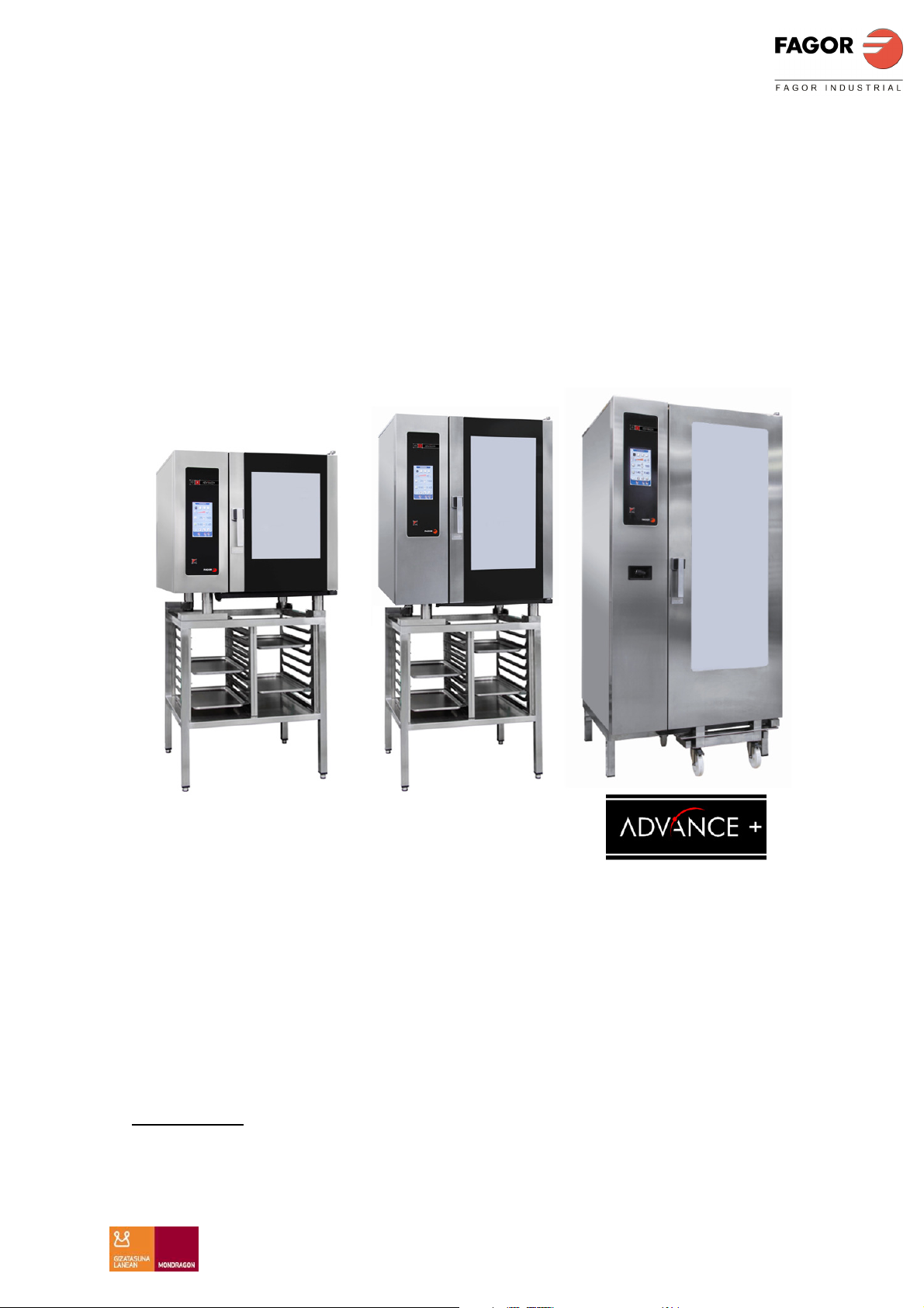
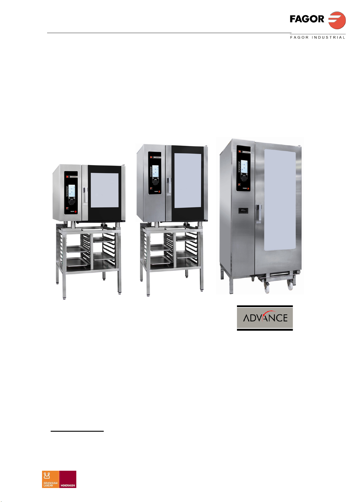
MODELOS: APE-061
APE-101
APE-201
APE-102
APE-202
1
Page 2

ESTIMADO CLIENTE
Agradecemos la confianza que ha depositado en nuestra marca al adquirir un
aparato de uso profesional. Estamos plenamente convencidos de que a medida
que pase el tiempo, quedará totalmente satisfecho de su compra.
Tómese unos minutos de su tiempo, acérquese con este manual al aparato y
“manos a la obra”: las informaciones gráficas de fácil compresión sustituyen a
las hojas llenas de texto.
No obstante, le aconsejamos estudie detenidamente este manual compilado
por los jefes de cocina de FAGOR, únicamente así podrá beneficiarse al
máximo de las múltiples posibilidades y ventajas que le brinda este aparato.
Conserve este manual cerca del aparato y en lugar siempre accesible.
Finalmente, le deseamos mucho éxito y gran satisfacción con su nuevo horno.
FAGOR INDUSTRIAL S. COOP.
B\ Santxolopetegi 22 aptdo 17
20560 Oñati (Gipuzkoa/Spain)
2
Page 3

ESPAÑOL
MANUAL DE INSTALACION ADVANCE PLUS
INDICE
INDICE ...................................................................................................................................................................... 3
INSTRUCCIÓNES GENERALES DE SEGURIDAD .......................................................................................... 4
INFORMACIÓN GENERAL ................................................................................................................................ 4
ADVERTENCIA ................................................................................................................................................... 4
INFORMACIÓN GENERAL DE USO .................................................................................................................. 4
MANUAL DE INSTALACIÓN ............................................................................................................................... 5
DISTANCIA MÍNIMA .......................................................................................................................................... 5
INSTALACIÓN MODELOS DE SOBREMESA .................................................................................................. 5
CONEXIÓN ELECTRICA .................................................................................................................................... 6
CONEXIÓN AGUA .............................................................................................................................................. 8
CONEXIÓN DE AGUAS RESIDUALES ............................................................................................................. 9
DIMENSIONES GENERALES Y ACOMETIDAS ............................................................................................ 10
INSTRUCCIONES DE DESPALETICADO ....................................................................................................... 15
3
Page 4

ESPAÑOL
MANUAL DE INSTALACION ADVANCE PLUS
INSTRUCCIÓNES GENERALES DE SEGURIDAD
INFORMACIÓN GENERAL
Durante periodos prolongados de parada del aparato se recomienda cortar la
alimentación de agua y corriente eléctrica.
ADVERTENCIA
La instalación, ajuste incorrecto, el servicio ó el mantenimiento inapropiados del
aparato así como la manipulación del mismo pueden provocar daños materiales como
lesiones. Antes de proceder a la puesta en servicio del aparato, leer detenidamente
las instrucciones de este manual.
No almacenar ni utilizar gases ó líquidos explosivos cerca del aparato, ni introducir
líquidos con contenido alcohólico dentro del aparato.
Estando el horno caliente no abrir de forma brusca la puerta (peligro de quemaduras
debido a la existencia de vahos calientes). No echar agua fría en el interior de la
cámara cuando esta se encuentra caliente.
Las reparaciones o manipulaciones realizadas por personal ajeno al SAT (servicio de
asistencia Técnico) FAGOR INDUSTRIAL o SAT autorizados conlleva una pérdida de
la garantía del horno.
Exija al instalador del horno la cumplimentación del CHECK LIST, comprobando:
• Conexión eléctrica
• Conexión Neumática
• Conexión Hidráulica
• Conexión aguas residuales
• Condiciones de instalación
• Condiciones de instalaciones
• Explicación al usuario del funcionamiento general del horno (uso y
mantenimiento)
Este aparato debe instalarse en un local suficientemente ventilado para impedir la
formación de concentraciones inadmisibles de sustancias nocivas para la salud.
INFORMACIÓN GENERAL DE USO
Antes de la primera puesta en marcha del aparato ya instalado, se recomienda limpiar
su interior con un paño impregnado de agua jabonosa y a continuación ponerlo en
marcha en vacío durante ½ hora en el modo Vapor para eliminar los olores
característicos de un aparato nuevo.
Antes de poner en marcha el aparato, compruebe que la llave del agua se encuentra
abierta.
Cuando el horno vaya a estar un largo tiempo sin ser utilizado se recomienda cerrar la
llave de paso de agua.
Abrir la puerta del horno con precaución para evitar quemarse con los vahos.
4
Page 5
ESPAÑOL
MANUAL DE INSTALACION ADVANCE PLUS
MANUAL DE INSTALACIÓN
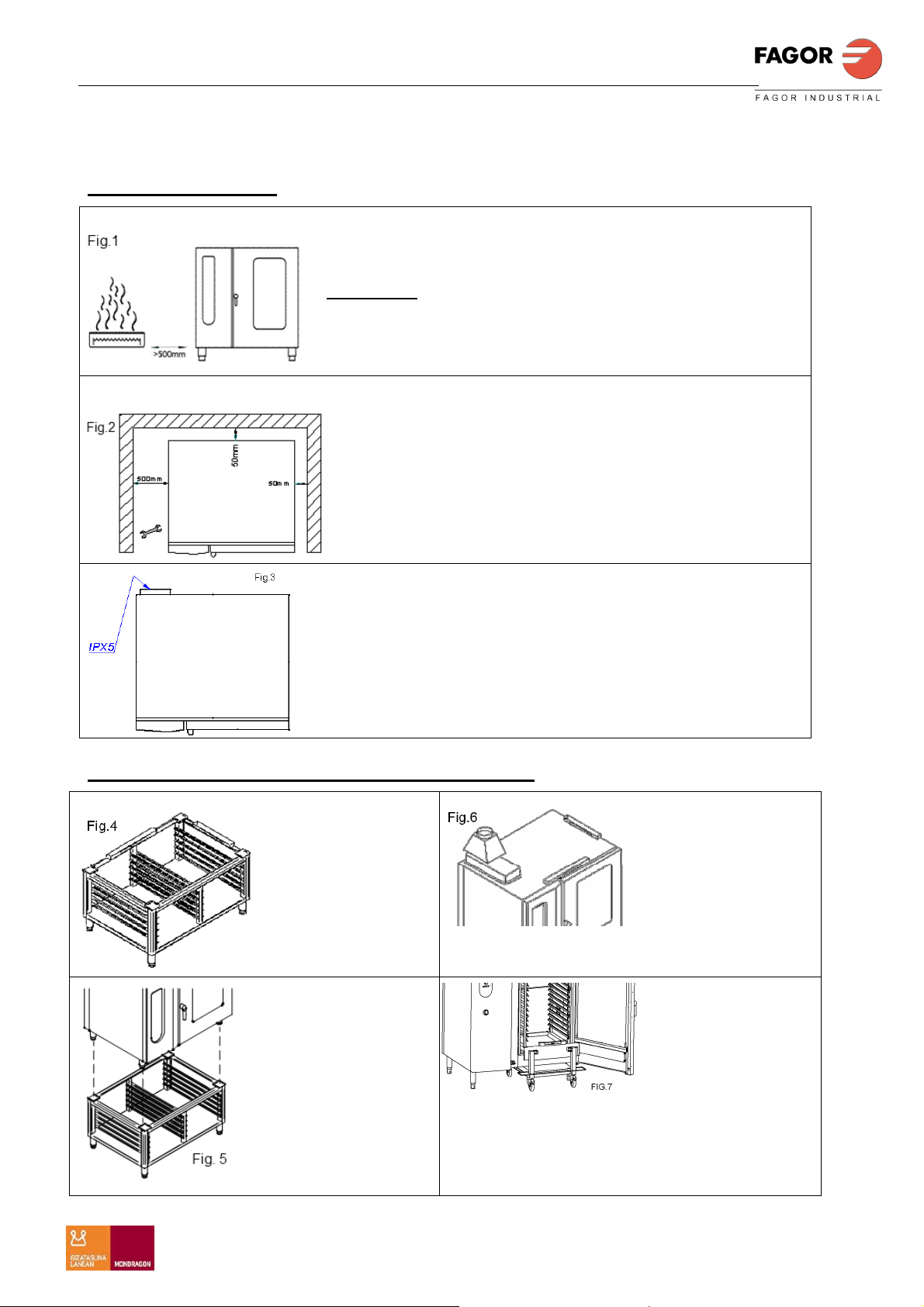
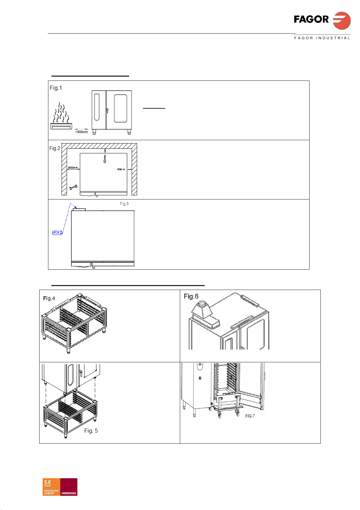
DISTANCIA MÍNIMA
Distancia mínima en el caso de fuentes de calor
por el lado izquierdo 400mm.Fig 1.
Atención: Una temperatura ambiente excesiva
por el lado izquierdo del aparato puede hacer
que la desconexión de seguridad del aparato se
active.
Aconsejamos mantener una distancia de
500mm en el lado izquierdo del aparato para
poder llevar a cabo trabajos de reparación y
mantenimiento.Fig.2.
Es obligatorio amarrar la chapa IPX5 en la parte
posterior de los hornos. Fig.3
Se aconseja asegurar la estabilidad de los
hornos
INSTALACIÓN MODELOS DE SOBREMESA
Nivelarbastidor
horizontalmente
antes de colocar el
horno sobre el
mismo. Fig.4
El aparato tiene
que estar nivelado
horizontalmente.
Fig.6
Apoyar el horno en
el bastidor haciendo
coincidir los apoyos
con las ubicaciones
que tiene el bastidor.
Fig 5
(Opcional en
modelo 202)
El carro móvil de
carga (opcional)
debe asentar en
posición horizontal en el aparato. Fig.7
5
Page 6
ESPAÑOL
MANUAL DE INSTALACION ADVANCE PLUS
CONEXIÓN ELECTRICA
La conexión eléctrica del aparato debe hacerse siempre por un TÉCNICO
AUTORIZADO.
Se deberá tener en cuenta las normas legales vigentes en cada país en materia de
conexiones a la red eléctrica.
Verificar que la tensión de la red corresponde a la que se indica en la placa de
características.
Para la conexión emplear cable manguera de polycloropreno u otro material de
similares características (Ho5RN-F).
Próximo al aparato debe instalarse un dispositivo interruptor para todas las fases, con
un mínimo de 3mm de apertura entre contactos. Este interruptor irá provisto de
fusibles.
Es obligatorio conectar a tierra el aparato, desde la regleta de conexiones del aparato
a la toma de tierra de la red eléctrica.
El fabricante no se hace responsable de posibles daños originados por el
incumplimiento de este requisito.
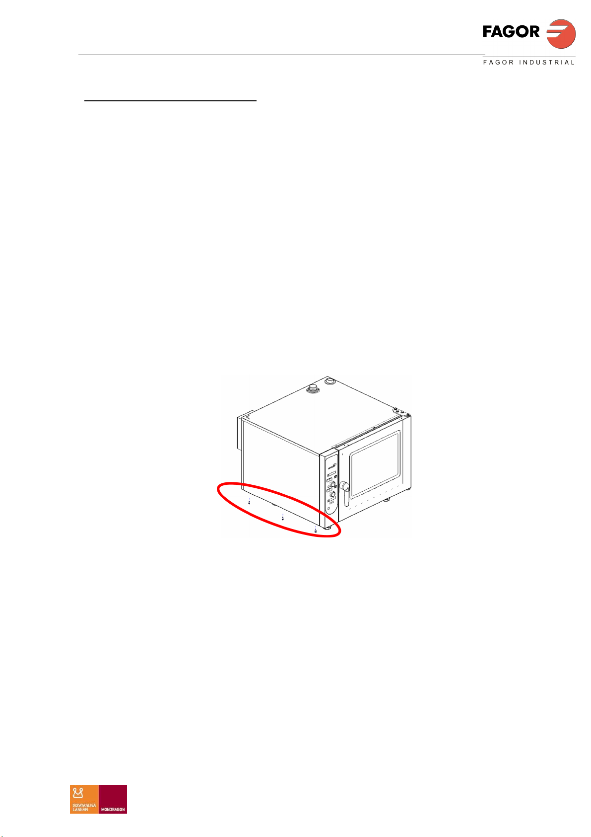
Para acceder a la regleta de conexión eléctrica del aparato soltar el panel lateral
izquierdo (Fig 8), pasar el cable manguera por el prensa estopas situado en la base
exterior y conectar según se indica en la regleta.
Fig. 8
MUY IMPORTANTE: Antes de colocar el panel lateral izquierdo fijar la manguera de
alimentación eléctrica fuertemente al prensaestopas.
Cuando se instalen varios aparatos en línea, deberán ser conectados entre sí a tierra,
por el punto destinado a tal fin, que se encuentra ubicado en la base del horno, zona
posterior.
6
Page 7
ESPAÑOL
MANUAL DE INSTALACION ADVANCE PLUS
SECCIÓN MANGUERA Y VALOR DE FUSIBLES
TENSIÓN
ALIMENTACIÓN
400V 3N
50-60Hz
230V 3N
50-60Hz
POTENCIA TOTAL KW 9,5
TENSIÓN
ALIMENTACIÓN
400V 3N
50-60Hz
230V 3N
50-60Hz
POTENCIA TOTAL KW 18,5
TENSIÓN
ALIMENTACIÓN
400V 3N
50-60Hz
230V 3N
50-60Hz
POTENCIA TOTAL KW 37
SECCIÓN
MANGUERA
3x1,5mm2 +N+T 16A 300mA
3x4mm²+N+ T 32A 300mA
SECCIÓN
MANGUERA
3x6mm2 +N+T 32A 300mA
3x10mm²+N+ T 63A 300mA
SECCIÓN
MANGUERA
3x16 mm2 +N+T 63A 300mA
3x35mm²+ T 100A 300mA
FUSIBLE
INT.
GENERAL
FUSIBLE
INT.
GENERAL
FUSIBLE
INT.
GENERAL
DISPOSITIVO
DIFERENCIAL
DISPOSITIVO
DIFERENCIAL
DISPOSITIVO
DIFERENCIAL
APE 061
APE 101
APE 201
TENSIÓN
ALIMENTACIÓN
400V 3N
50-60Hz
230V 3N
50-60Hz
POTENCIA TOTAL KW 30
TENSIÓN
ALIMENTACIÓN
400V 3N
50-60Hz
230V 3N
50-60Hz
POTENCIA TOTAL KW 61
SECCIÓN
MANGUERA
3x10mm2 +N+T 63A 300mA
3x25mm²+ T 100A 300mA
SECCIÓN
MANGUERA
3x25mm2 +N+T 125A 300mA
3x70mm²+ T 180A 300mA
FUSIBLE
INT.
GENERAL
FUSIBLE
INT.
GENERAL
DISPOSITIVO
DIFERENCIAL
DISPOSITIVO
DIFERENCIAL
APE 102
APE 202
7
Page 8
ESPAÑOL
MANUAL DE INSTALACION ADVANCE PLUS
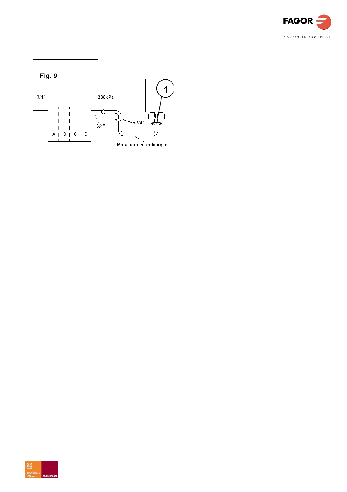
CONEXIÓN AGUA
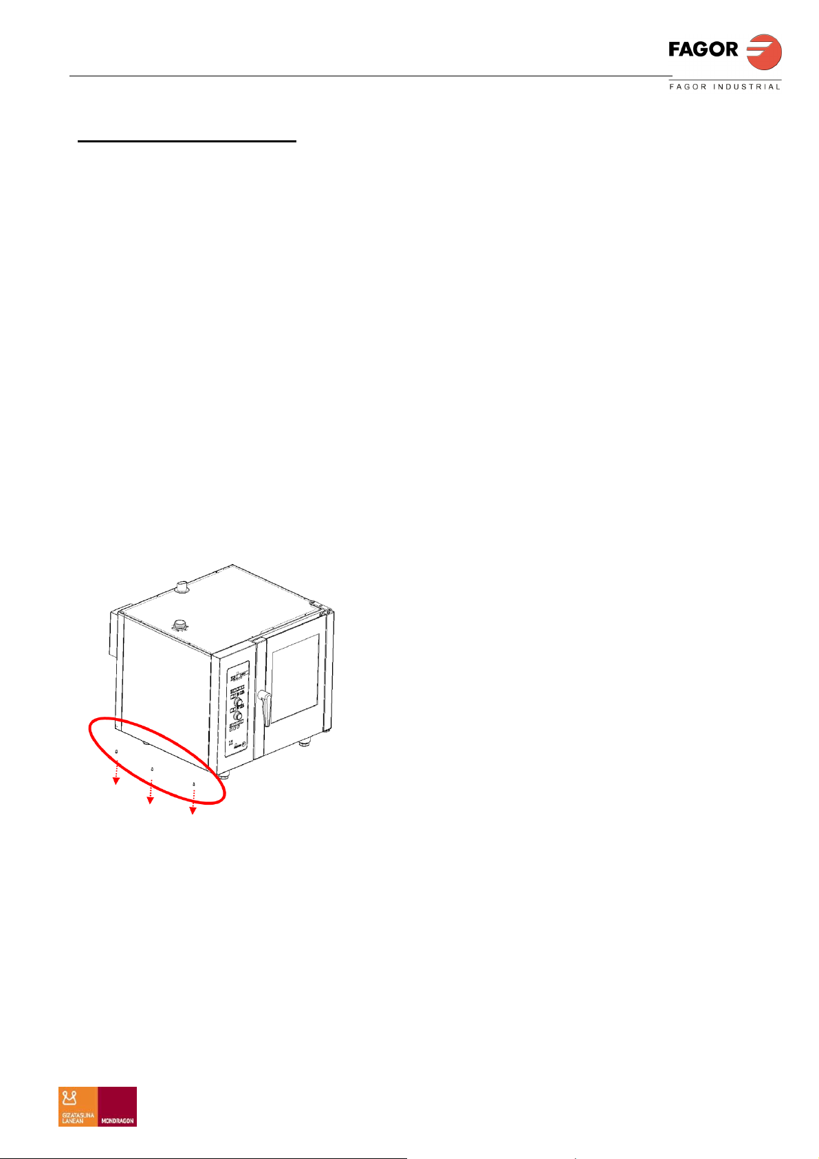
Conectar al aparato solo agua potable.
Realizar la conexión a la red de agua
por el punto 1 (Fig 9), utilizando la
manguera que se suministra.
La presión de entrada de agua debe
estar comprendida entre 200 y 400 kPa
(2-4 kg/mm2). Se aconseja 200 kPa
El agua tiene que tener las siguientes propiedades:
• PH 6.5÷7.5
• Cloruros < 150mg/litro
• Concentración de Cloro 0.2÷0.5 mg/litro
• Conductividad 400÷2000 µS
• Impurezas de agua Ø < 0.08mm
•
Dureza de agua 5-10ºF
Filtros aconsejados:
A) Filtro fino.
En caso de que el agua contenga impurezas como arena, partículas de hierro o
sustancias que floten en la misma, aconsejamos utilizar un filtro fino a la entrada.
B) Filtro de carbón activado.
En caso de que el agua contenga una concentración elevada de cloro por encima de
0,2 mg/l (ppm) (esta información puede obtenerse en la compañía de aguas) deberá
intercalarse un filtro de carbón activado.
C) Instalación de recirculación de ósmosis.
Cuando la concentración de cloruros sobrepase los 150 mg/l (ppm) (la información
puede obtenerse en la compañía de aguas), deberá preverse una instalación de
recirculación de ósmosis. En este caso tener en cuenta que el valor mínimo de
conductancia debe ser de 400µS.
D) Descalcificación del agua:
Se aconseja para el tratamiento del agua en los casos que según la experiencia del
grado de calcinación sea elevado (sin carga de cloruro). Sistemas: H+. Intercambio de
iones o Kleensteam. Desaconsejamos encarecidamente el uso de intercambiadores
de sodiones (como es habitual en los lavavajillas) a causa de los sedimentos de sodio
y del retraso de ebullición con sal común.
En la selección de sistemas de filtro (A, B, C, D) aconsejamos el fabricante: BRITA
Advertencia
Antes de la conexión fijarse en la pegatina que indica cual es la entrada de agua.
8
Page 9
ESPAÑOL
MANUAL DE INSTALACION ADVANCE PLUS
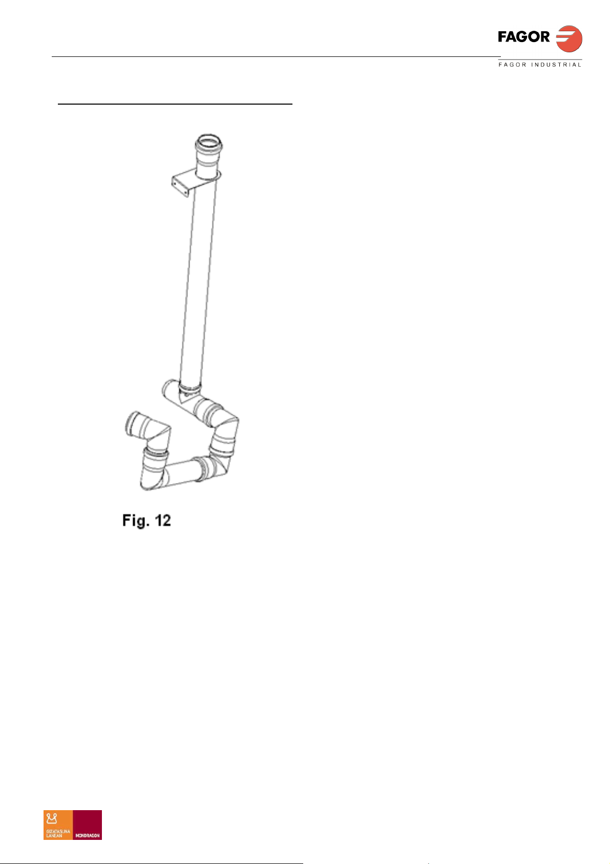
CONEXIÓN DE AGUAS RESIDUALES
Utilizar tubo resistente a la temperatura
del vapor, ningún tubo flexible.
El desagüe se puede instalar utilizando
un sifón estándar conectado a una rejilla
o tanque abierto. Para el óptimo
rendimiento del horno se recomienda
utilizar el KIT desagüe del fabricante,
referencia 19012125. Fig. 12
Observar las dimensiones adecuadas
para el desagüe:
-Volumen de bombeo del generador de
vapor en un espacio reducido de tiempo:
0,7 l/seg.
-Temperatura media del agua residual:
65ºC
9
Page 10
ESPAÑOL
MANUAL DE INSTALACION ADVANCE PLUS
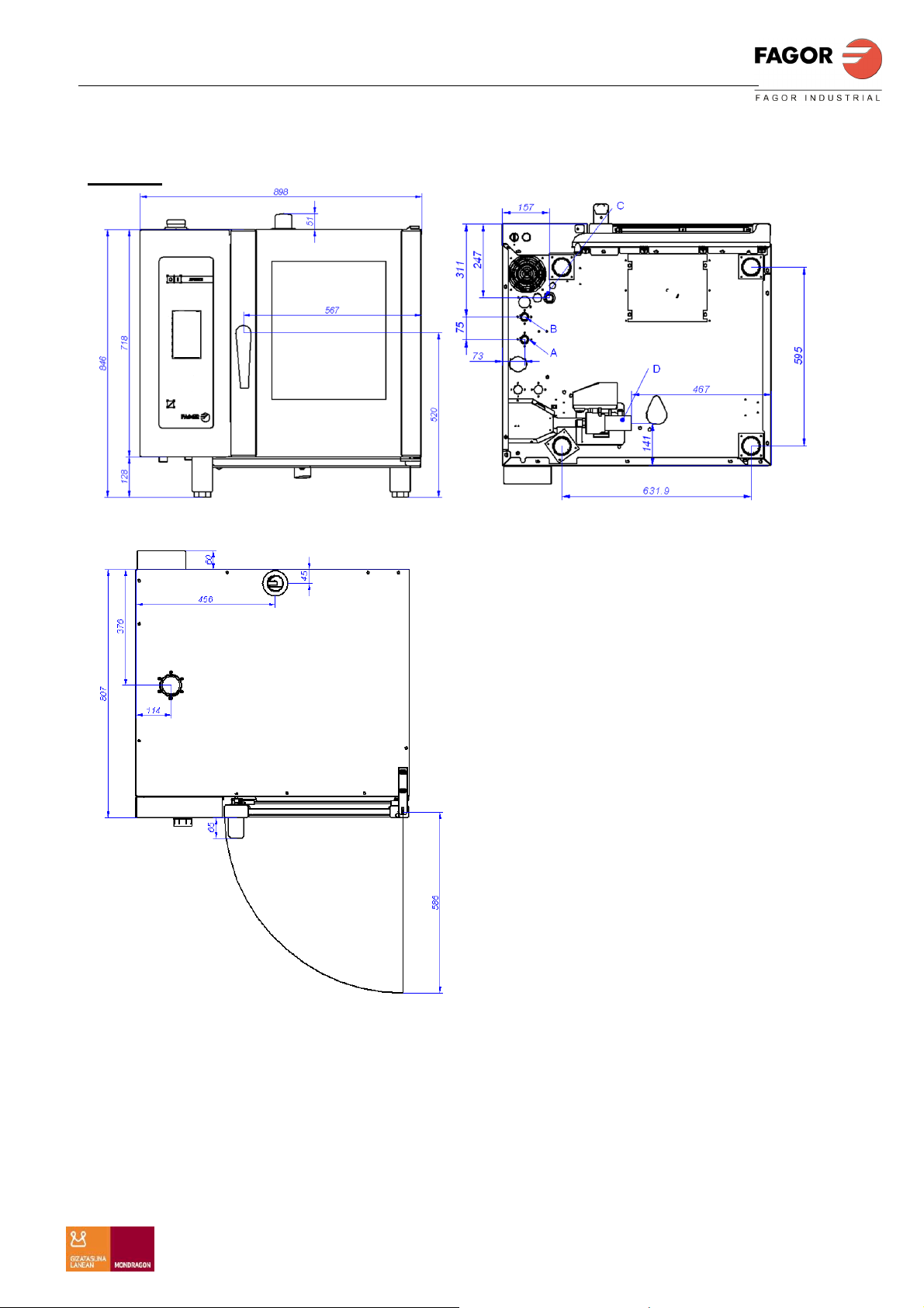
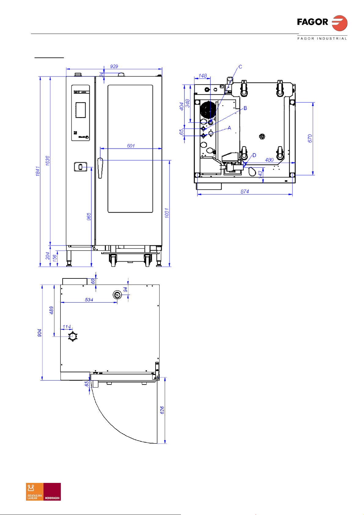
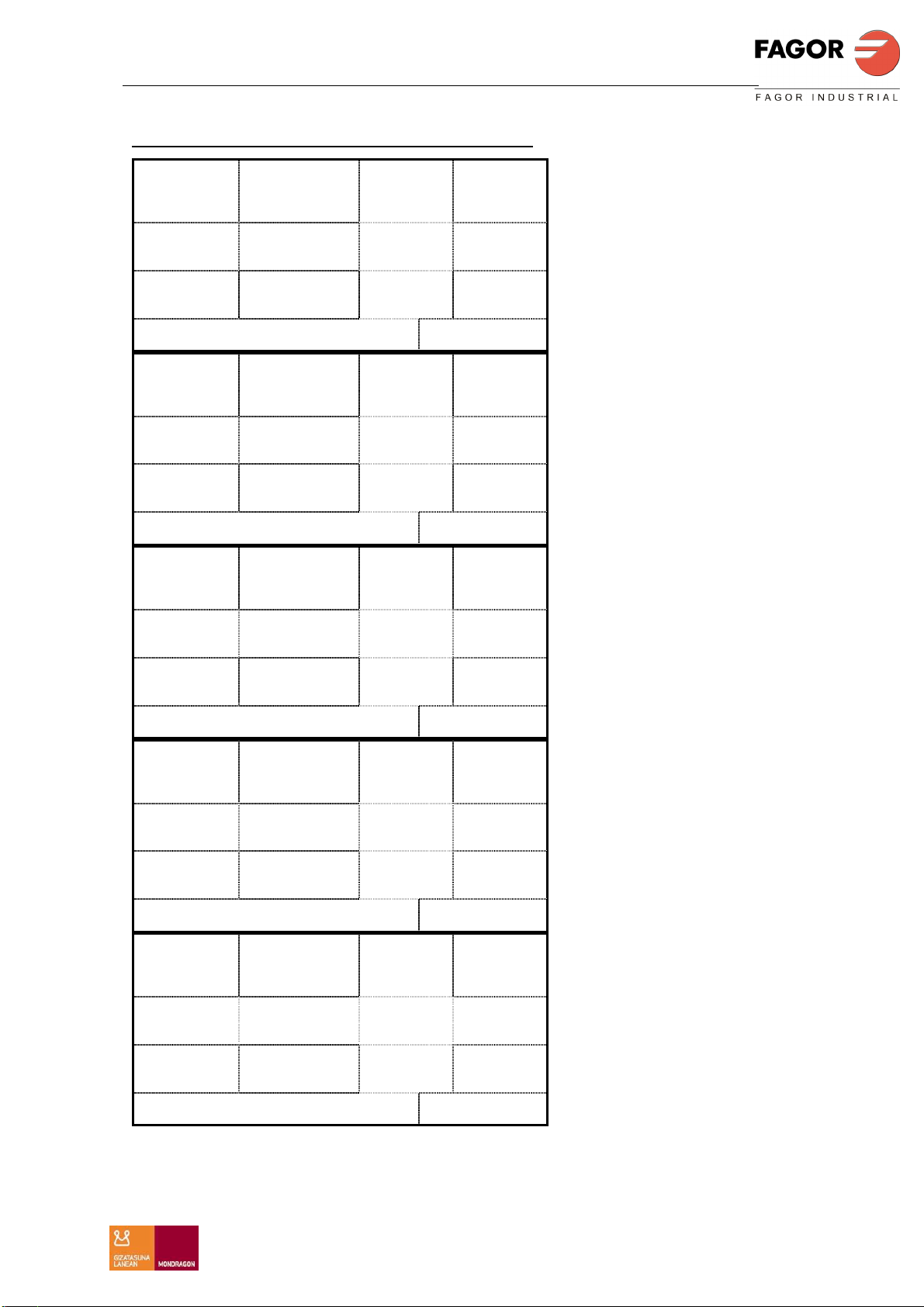
DIMENSIONES GENERALES Y ACOMETIDAS
APE 061
A: Entrada de agua blanda
B: Entrada de agua dura
C: Alimentación eléctrica
D: Desagüe
10
Page 11
ESPAÑOL
MANUAL DE INSTALACION ADVANCE PLUS
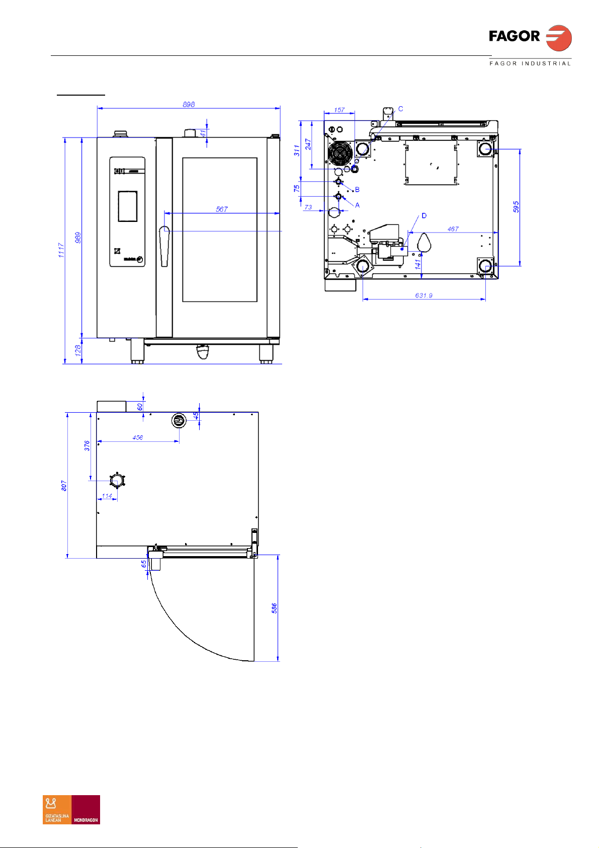
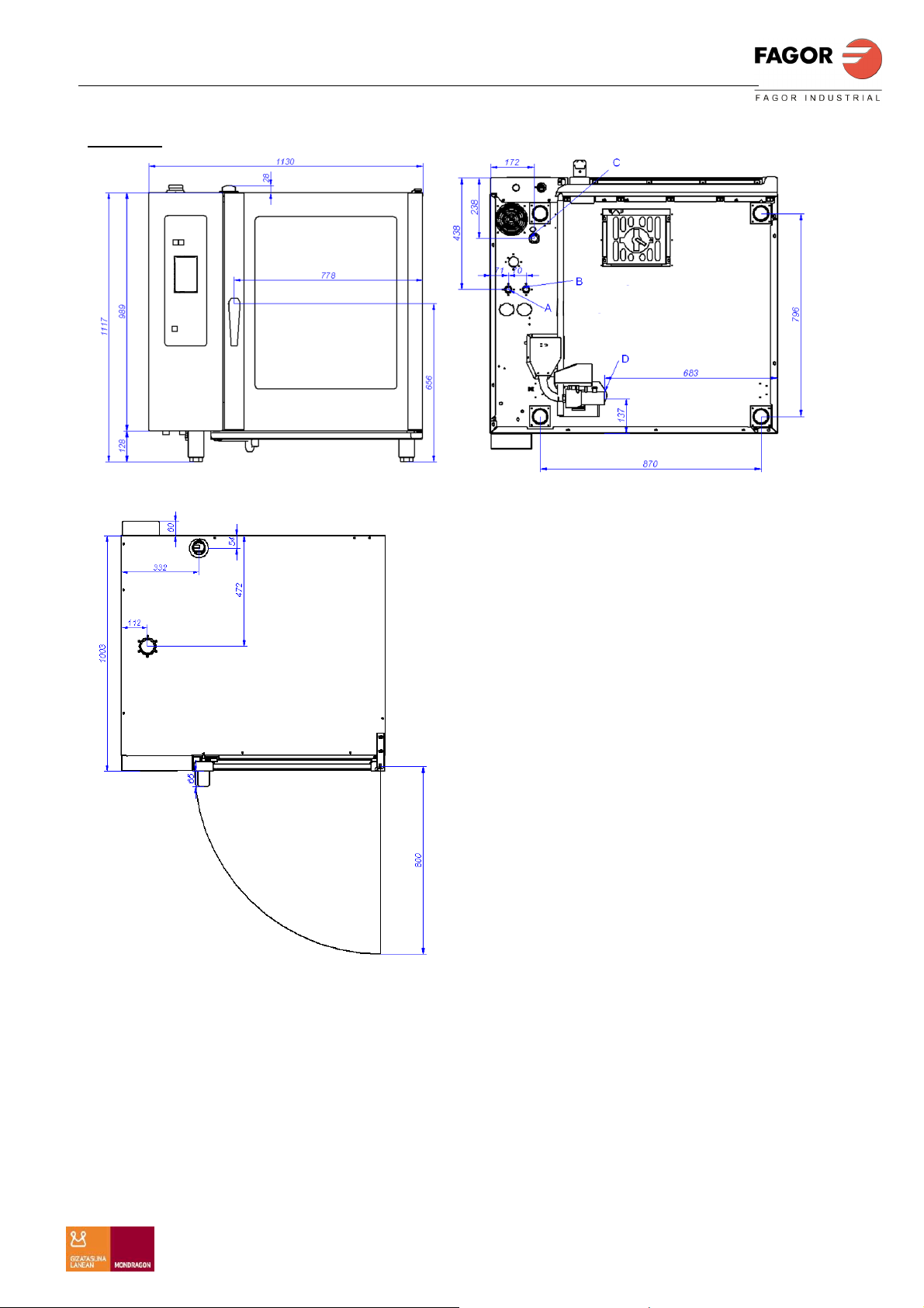
APE 101
A: Entrada de agua blanda
B: Entrada de agua dura
C: Alimentación eléctrica
D: Desagüe
11
Page 12
ESPAÑOL
MANUAL DE INSTALACION ADVANCE PLUS
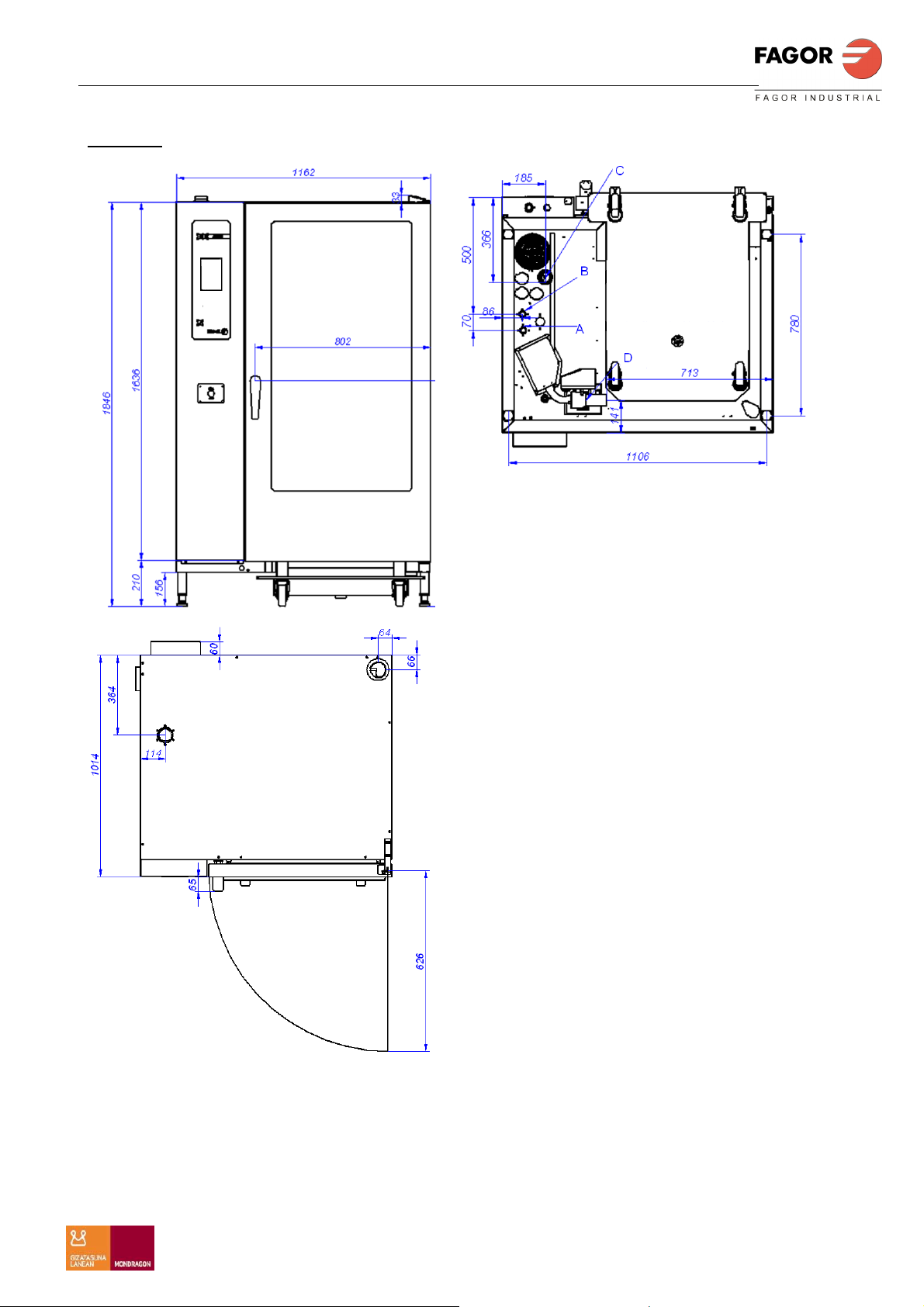
APE 201
A: Entrada de agua blanda
B: Entrada de agua dura
C: Alimentación eléctrica
D: Desagüe
12
Page 13
ESPAÑOL
MANUAL DE INSTALACION ADVANCE PLUS
APE 102
A: Entrada de agua blanda
B: Entrada de agua dura
C: Alimentación eléctrica
D: Desagüe
13
Page 14
ESPAÑOL
MANUAL DE INSTALACION ADVANCE PLUS
APE 202
A: Entrada de agua blanda
B: Entrada de agua dura
C: Alimentación eléctrica
D: Desagüe
14
Page 15
ESPAÑOL
MANUAL DE INSTALACION ADVANCE PLUS
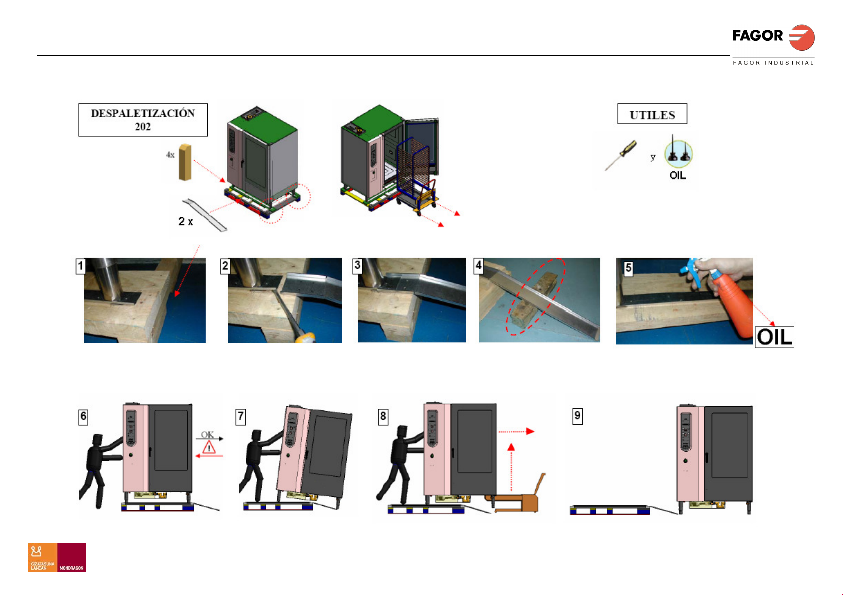
INSTRUCCIONES DE DESPALETICADO
15
Page 16
ENGLISH
INSTALLATION MANUAL ADVANCE PLUS
INSTALLATION MANUAL
12044977
16
MODELS: AE 061
AE 101
AE 201
AE 102
AE 202
Page 17

ENGLISH
INSTALLATION MANUAL ADVANCE PLUS
DEAR CUSTOMER
We would like to thank you for the confidence you have shown in our product on
purchasing a professional appliance. We are totally convinced that in time you
will be completely satisfied with your purchase.
Take a few minutes of your time and get to know the appliance with this
instructions manual and "down to work": the easy to understand graphical
information replaces pages full of writing.
Nevertheless, we recommend you thoroughly read this manual compiled by
FAGOR's kitchen supervisors, in order to benefit to the maximum from the
multiple possibilities and advantages this appliance offers you.
Keep this manual near to the appliance and at all times in an accessible place.
Lastly, we wish you success and hope that you will be fully satisfied with your
new oven.
FAGOR INDUSTRIAL S. COOP.
B\ Santxolopetegi 22 aptdo 17
20560 Oñati (Gipuzkoa/Spain)
17
Page 18

ENGLISH
INSTALLATION MANUAL ADVANCE PLUS
CONTENTS
CONTENTS ............................................................................................................................................................ 18
GENERAL SAFETY INSTRUCTIONS .............................................................................................................. 19
GENERAL INFORMATION .............................................................................................................................. 19
WARNING .......................................................................................................................................................... 19
GENERAL INFORMATION FOR USE.............................................................................................................. 19
INSTALLATION MANUAL ................................................................................................................................ 20
MINIMUM DISTANCE ...................................................................................................................................... 20
INSTALLATION OF TABLE TOP MODELS ................................................................................................... 20
ELECTRICAL CONNECTION .......................................................................................................................... 21
WATER CONNECTION .................................................................................................................................... 23
WASTE WATER CONNECTION ...................................................................................................................... 24
GENERAL MEASUREMENTS AND CONNECTIONS ................................................................................... 25
REMOVAL FROM PALLETS INSTRUCTIONS .............................................................................................. 30
18
Page 19

ENGLISH
INSTALLATION MANUAL ADVANCE PLUS
GENERAL SAFETY INSTRUCTIONS
GENERAL INFORMATION
If the appliance is not used for long periods of time, the water and electricity
supplies should be disconnected.
WARNING
The installation, incorrect adjustment, inappropriate maintenance or use of the
appliance may cause material damages and injuries. Before commissioning the
appliance, carefully read the instructions contained in this manual.
Do not store or use gases or explosive liquids near the appliance, or introduce
liquids containing alcohol inside the machine.
When the oven is hot, do not open the door suddenly (danger of burns due to
hot steam). Do not put cold water in the chamber when it is hot.
Repairs or adjustments carried out by personnel not belonging to FAGOR
INDUSTRIAL SAT (Technical Assistance Service) or an authorised SAT will
imply the cancellation of the oven warranty.
The installer of the oven must complete the CHECK LIST, after checking the
following:
• Electrical connection
• Pneumatic connection
• Hydraulic connection
• Waste water connection
• Conditions of installation
• Conditions of installations
• Explication to user of the general working of the oven (use and
maintenance)
GENERAL INFORMATION FOR USE
Before switching on the newly installed appliance for the first time, the inside
should be cleaned with a cloth soaked in soapy water. Then switch on the
empty oven in Steam mode for ½ hour to eliminate the odours associated with a
new appliance.
Before switching on the appliance, check that the mains water tap is open.
If the oven is not going to be used for a long period of time, the mains water tap
should be closed.
Open the oven door carefully to avoid burns from the steam.
The oven should always be installed below a steam extractor hood.
19
Page 20
ENGLISH
INSTALLATION MANUAL ADVANCE PLUS
INSTALLATION MANUAL
MINIMUM DISTANCE
Minimum distance from other sources of heat on the left
side 400 mm. Fig. 1
Warning: An excessive room temperature on the left-hand
side of the appliance may trigger the appliance safety
disconnection.
We recommend a distance of 500 mm on the left-hand side
of the appliance to leave room for repair and maintenance
work.
Fig. 2
In any case the unit must maintain a minimum distance of 50
mm. with respect to the walls.
The IPX5 plate must be fastened on the rear of the ovens.
Fig. 3
Check the ovens are stable
INSTALLATION OF TABLE TOP MODELS
Level the frame
horizontally before
placing the oven on the
frame.
Fig. 4
Rest the oven on the
frame and line up the
supports with the holes
on the frame.
Fig. 5
The appliance
must be
horizontally
level.
Fig. 6
(Optional in
model 202)
The mobile load
trolley (optional)
must be
horizontal on the
appliance.
20
Fig. 7
Page 21
ENGLISH
INSTALLATION MANUAL ADVANCE PLUS
ELECTRICAL CONNECTION
An AUTHORISED TECHNICIAN should always carry out the appliance’s
electrical connection.
The legal standards in force in each country on connections to the mains should
be taken into account.
Check that the mains voltage corresponds to that indicated on the nameplate.
Use polychloroprene cable sleeves or other similar materials (Ho5RN-F).
A switch device should be installed next to the appliance for all the phases, with
a gap of a minimum of 3 mm between contacts. This switch will be equipped
with fuses.
The appliance must be earthed, from the connection strip of the appliance to the
earth connection of the main power supply.
The manufacturer will not be held liable for damage originated by failure to
observe this requirement.
To access the connection strip, release the left side panel (Fig 8), pass the
cable hose through the stuffing box on the exterior base and connect as shown
on the strip.
Fig. 8
VERY IMPORTANT: Before installing the left side panel, attach the electrical
supply hose securely to the stuffing box.
When several appliances are installed in series, they should be earthed to each
other using the point assigned for this purpose, located in the fryers base, at the
back.
21
Page 22
ENGLISH
INSTALLATION MANUAL ADVANCE PLUS
HOSE CROSS SECTION AND FUSE RATINGS
SUPPLY
VOLTAGE
400 V 3N
50-60Hz
230 V 3N
50-60Hz
SUPPLY
VOLTAGE
400 V 3N
50-60Hz
230 V 3N
50-60Hz
SUPPLY
VOLTAGE
400 V 3N
50-60Hz
230 V 3N
50-60Hz
CABLE
TOTAL POWER kW
TOTAL POWER kW
TOTAL POWER kW
SECTION
3x1.5 mm2 + N+T
3x4 mm²+T
CABLE
SECTION
3x6 mm2 + N+T
3x10 mm²+T
CABLE
SECTION
3x16 mm2 +N+T
3x35 mm²+T
FUSE
RING FUSE
16 A
32 A
FUSE
RING FUSE
32 A
63 A
FUSE
RING FUSE
63 A
100 A
DIFFERENTIA
DEVICE
300 mA
300 mA
9.5
DIFFERENTIA
DEVICE
300 mA
300 mA
18.5
DIFFERENTIA
DEVICE
300 mA
300 mA
37
L
APE 061
L
APE 101
L
APE 201
SUPPLY
VOLTAGE
400 V 3N
50-60Hz
230 V 3N
50-60Hz
SUPPLY
VOLTAGE
400 V 3N
50-60Hz
230 V 3N
50-60Hz
CABLE
TOTAL POWER kW
TOTAL POWER kW
SECTION
3x10 mm2 + N+T
3x25 mm²+T
CABLE
SECTION
3x25 mm2 + N+T
3x70 mm²+T
RING FUSE
RING FUSE
FUSE
63 A
100 A
FUSE
125 A
180 A
DIFFERENTIA
L
DEVICE
300 mA
300 mA
30
DIFFERENTIA
L
DEVICE
300 mA
300 mA
61
APE 102
APE 202
22
Page 23

ENGLISH
Water inlet hose Fig 9
INSTALLATION MANUAL ADVANCE PLUS
WATER CONNECTION
3/4"
300kPa
Only connect drinking water to the appliance.
Connect the appliance to the mains water
supply at point 1 (Fig9) using the hose
supplied.
The pressure of the incoming water should
be between 200 and 400 kPa (2-4 kg/mm2).
We recommend 250 kPa.
A B C D
3/4"
R3/4"
Manguera entrada agua
The water used should have the following properties:
PH 6.5÷7.5
Chlorides < 150mg/litre
Chlorine concentration 0.2÷0.5 mg/litre
Conductivity 400÷2000 µS
Water impurities Ø < 0.08 mm
Water hardness 5-10ºF
Recommended filters:
A) Fine filter.
If the water contains impurities such as sand, iron particles or floating
substances, we recommend the use of a fine filter at the water input.
B) Activated carbon filter.
If the water has a high chlorine content over 0.2 mg/l (ppm) (this information can
be obtained from the relevant water board), an activated carbon filter should be
installed.
C) Installation of osmosis recirculation.
When the chloride concentration is above 150 mg/l (ppm) (this information can
be obtained from the relevant water board), an osmosis recirculation installation
should be mounted. In this case, please remember that the minimum
conductivity value is 400 µS/cm.
D) Water descaling:
For water with a high level of limescale (without chloride load) the water should
be treated. Systems: H+. Interchange of ions or Kleensteam. We strongly
advise against the use of sodium exchangers (normally used in dish washers)
due to the formation of sodium sediment and the delay in boiling with common
salt.
We recommend the manufacturer, Britta, for the selection of filter systems (A, B,
C, D).
Warnin
:
Before connection, look at the label that shows which is the water inlet.
23
Page 24

ENGLISH
INSTALLATION MANUAL ADVANCE PLUS
WASTE WATER CONNECTION
Use steam temperature resistant
tubing, any flexible hose.
The drain can be installed using a
U-bend. For the optimum
performance it is recommended to
use the drain KIT reference
19012125. Fig12
Observe the proper dimensions for
drainage:
-The pumping volume of the steam
generator in a small space of time:
0,7l/sec
- The average residual water
temperature :65ºC
24
Page 25

ENGLISH
INSTALLATION MANUAL ADVANCE PLUS
GENERAL MEASUREMENTS AND CONNECTIONS
APE 061
A: Check-in soft water
B: Check-in hard water
C: Power
D: Drain
25
Page 26

ENGLISH
INSTALLATION MANUAL ADVANCE PLUS
APE 101
A: Check-in soft water
B: Check-in hard water
C: Power
D: Drain
26
Page 27

ENGLISH
INSTALLATION MANUAL ADVANCE PLUS
APE 201
A: Check-in soft water
B: Check-in hard water
C: Power
D: Drain
27
Page 28

ENGLISH
INSTALLATION MANUAL ADVANCE PLUS
APE 102
A: Check-in soft water
B: Check-in hard water
C: Power
D: Drain
28
Page 29

ENGLISH
INSTALLATION MANUAL ADVANCE PLUS
APE 202
A: Check-in soft water
B: Check-in hard water
C: Power
D: Drain
29
Page 30

ENGLISH
INSTALLATION MANUAL ADVANCE PLUS
REMOVAL FROM PALLETS INSTRUCTIONS
30
Page 31

DEUTSCH
INSTALLATIONS HANDBUCH ADVANCE PLUS
INSTALLATIONSHANDBUCH
12044977
31
MODELLE: APE 061
APE 101
APE 201
APE 102
APE 202
Page 32

DEUTSCH
INSTALLATIONS HANDBUCH ADVANCE PLUS
SEHR GEEHRTER KUNDE,
wir danken Ihnen für das Vertrauen, das Sie uns mit dem Kauf eines für den
professionellen Gebrauch bestimmten Gerätes unserer Marke bewiesen haben.
Wir sind fest davon überzeugt, dass Sie auch nach langer Zeit noch
vollkommen zufrieden mit Ihrem Kauf sein werden.
Nehmen Sie sich einige Minuten Zeit, begeben Sie sich mit diesem Handbuch
zum Gerät und „Hand ans Werk“: die leicht verständlichen Bildinformationen
ersetzen die bisher verwendeten Volltextseiten.
Allerdings raten wir Ihnen dazu, das vorliegende, von den FAGOR-Küchenchefs
verfasste Handbuch gründlich durchzulesen, da Sie nur so in den Genuß der
vielfältigen Möglichkeiten und Vorteile dieses Gerätes kommen können.
Bewahren Sie dieses Handbuch stets in Gerätenähe und an einem gut
zugänglichen Ort auf.
Abschließend wünschen wir Ihnen viel Erfolg und Freude mit Ihrem neuen
Gerät.
FAGOR INDUSTRIAL S. COOP.
B\ Santxolopetegi, 22 Aptdo. 17
20560 Oñati (Gipuzkoa/Spain)
32
Page 33

DEUTSCH
INSTALLATIONS HANDBUCH ADVANCE PLUS
INHALTSVERZEICHNIS
INHALTSVERZEICHNIS .................................................................................................................................... 33
ALLGEMEINE SICHERHEITSANWEISUNGEN ............................................................................................ 34
ALLGEMEINE INFORMATIONEN .................................................................................................................. 34
HINWEIS ............................................................................................................................................................ 34
ALLGEMEINE INFORMATIONEN .................................................................................................................. 34
INSTALLATIONSHANDBUCH .......................................................................................................................... 35
MINDESTABSTAND ......................................................................................................................................... 35
INSTALLATION DER TISCHGERÄTE ........................................................................................................... 35
ELEKTRISCHER ANSCHLUSS ........................................................................................................................ 36
WASSERANSCHLUSS ...................................................................................................................................... 38
ABWASSERANSCHLUSS ................................................................................................................................ 39
ALLGEMEINE ABMESSUNGEN UND ZULEITUNGEN ............................................................................... 40
PALETTE ANWEISUNGEN ZUM ENTFERNEN ............................................................................................ 45
33
Page 34

DEUTSCH
INSTALLATIONS HANDBUCH ADVANCE PLUS
ALLGEMEINE SICHERHEITSANWEISUNGEN
ALLGEMEINE INFORMATIONEN
Bei längerer Inaktivität des Gerätes wird werkseitig dazu geraten, die Wasser- und
Stromversorgung zu unterbrechen.
HINWEIS
Die unsachgemäße Installation, Einstellung, Bedienung oder Wartung bzw.
Handhabung des Gerätes kann sowohl Sach- als auch Personenschäden verursachen.
Die im vorliegenden Handbuch enthaltenen Anweisungen vor der Inbetriebnahme des
Gerätes gründlich durchlesen.
In Gerätenähe dürfen keine explosiven Flüssigkeiten oder Gase gelagert werden.
Weiterhin dürfen keine alkoholhaltigen Flüssigkeiten in das Gerät gefüllt werden.
Ruckartiges Öffnen der Gerätetür bei heißem Gerät unbedingt vermeiden
(Verbrennungsgefahr aufgrund des heißen Dampfes). Kein Kaltwasser in das heiße
Geräteinnere einfüllen.
Die Durchführung von Reparaturen oder Eingriffen durch externes Personal, das nicht
zum Kundendienst (SAT) von FAGOR INDUSTRIAL gehört oder ausdrücklich hierzu
autorisiert ist, führt zum sofortigen Erlöschen der Garantie des Gerätes.
Der Installateur des Gerätes muss die CHECK LIST gewissenhaft abarbeiten und
ausfüllen. In diesem Sinne sind folgende Überprüfungen vorzunehmen:
• Elektrischer Anschluss
• Pneumatischer Anschluss
• Hydraulischer Anschluss
• Abwasseranschluss
• Installationsbedingungen
• Installationsbedingungen
• Gründliche Erklärung der allgemeinen Funktionsweise des Gerätes (Gebrauch
und Wartung)
Dieses Gerät muss an einem ausreichend belüfteten um die Bildung von
unannehmbaren Konzentrationen gesundheitsschädlicher Stoffe zu verhindern
installiert werden.
ALLGEMEINE INFORMATIONEN
Vor der ersten Inbetriebnahme des bereits installierten Gerätes wird werkseitig
empfohlen, das Geräteinnere mit einem in Seifenwasser getränkten Lappen zu
reinigen. Anschließend sollte das Gerät eine halbe Stunde lang im Leerlauf betrieben
werden, um den für Neugeräte typischen Geruch zu beseitigen.
Vor der Inbetriebnahme des Gerätes muß geprüft werden, ob sich der Wasserhahn in
der Offenstellung befindet.
Soll das Gerät für einen längeren Zeitraum außer Betrieb genommen werden, so wird
werkseitig empfohlen, den Wasserhahn zu schließen.
Öffnen Sie die Tür vorsichtig, um nicht von Dampf verbrüht.
Die Gerätetür vorsichtig öffnen, um Verbrennungen durch den austretenden Dampf zu
vermeiden.
Das Gerät muß in jedem Fall unter einer Abzugshaube aufgestellt werden.
34
Page 35

DEUTSCH
INSTALLATIONS HANDBUCH ADVANCE PLUS
INSTALLATIONSHANDBUCH
MINDESTABSTAND
Mindestabstand von Wärmequellen an der linken
Seite 500mm. Fig. 1
Achtung: Eine zu hohe Umgebungstemperatur an
der linken Gerätseite kann zum Auslösen der
Sicherheitsabschaltung des Gerätes führen
Zur Durchführung der Reparatur- und
Wartungsarbeiten wird werkseitig zu einem
Abstand von 500 mm an der linken Geräteseite
geraten.
Fig. 2
Das Blech IPX5 muß ordnungsgemäß im hinteren
Bereich des Gerätes befestigt werden.
Fig. 3
Die ordnungsgemäße Standfestigkeit des
Gerätes muß überprüft werden.
INSTALLATION DER TISCHGERÄTE
Den Ständer vor
dem Aufsetzen
des Gerätes
waagerecht
ausnivellieren.
Fig. 4
Das Gerät auf
den Ständer
aufsetzen, wobei
die
Halteelemente
des Gerätes mit
denen des
Ständers
übereinstimmen
müssen.Fig. 5
Fig 7
Das Gerät muß
waagerecht
ausnivelliert sein.
Fig 6
(Option für das
Modell 202)
Der Fahrwagen
(Option) muß
waagerecht in das
Gerät eingeführt
werden.
35
Page 36

DEUTSCH
INSTALLATIONS HANDBUCH ADVANCE PLUS
ELEKTRISCHER ANSCHLUSS
Der elektrische Anschluß des Gerätes muß von einem AUTORISIERTEN
FACHTECHNIKER vorgenommen werden.
Die am Aufstellungsort des jeweiligen Landes gültigen Normen in Verbindung
mit dem Anschluß an die Spannungsversorgung müssen beachtet werden.
Die Netzspannung muß mit der auf dem Typenschild angegebenen Spannung
übereinstimmen.
Stromkabel sollten flexible Leitungen mit ölbeständigem ausgedehnt werden,
und sollte nicht leichter als gewöhnliche Kabelmantel normalen Polychloropren
oder gleichwertigem synthetischen Elastomer (H05RN-F).
In Gerätenähe ist eine Unterbrechungsvorrichtung für alle Phasen mit einer
Mindestöffnung von 3 mm zwischen den Kontakten vorzusehen. Dieser
Schalter ist mit Sicherungen zu versehen.
Das Gerät muß vorschriftsmäßig über die Anschlußleiste des Gerätes und den
entsprechenden Erdungsanschluß der Spannungsversorgung geerdet werden.
Der Hersteller lehnt jede Verantwortung für mögliche Schäden ab, die auf die
Nichteinhaltung dieser Anforderung zurückzuführen sind.
Für den Zugang zur Anschlußleiste des Gerätes muß das linke seitliche Panel
abgenommen werden (Fig8). Den Kabelschlauch durch die an der Außenplatte
befindlichen Stopfbuchse hindurchführen und den Anschluß wie dargestellt
vornehmen.
Abb. 1
SEHR WICHTIG: Vor dem Anbringen des linken seitlichen Panels muß die
Zuleitung ordnungsgemäß an der Stopfbuchse befestigt werden.
Werden mehrere Geräte hintereinander angeschlossen, so müssen sie
untereinander an der hierfür jeweils vorgesehenen Stelle an den
Erdungsanschluß angeschlossen werden, der sich im hinteren Bereich der
Grundplatte des Gerätes befindet.
36
Page 37

DEUTSCH
INSTALLATIONS HANDBUCH ADVANCE PLUS
SCHLAUCHQUERSCHNITT UND SICHERUNGEN
VERSORGUNGS-
SPANNUNG
400V 3N
50-60 Hz
230 V 3N
50-60 Hz
GESAMTANSCHLUSSWERT KW 9,5
VERSORGUNGS-
SPANNUNG
400V 3N
50-60 Hz
230 V 3N
50-60 Hz
GESAMTANSCHLUSSWERT KW 18,5
VERSORGUNGS-
SPANNUNG
400V 3N
50-60 Hz
230 V 3N
50-60 Hz
GESAMTANSCHLUSSWERT KW 37
QUERSCHNITT
SCHLAUCH
3 x 1,5 mm2 + N+T 16A 300 mA
3x4 mm² + T 32A 300 mA
QUERSCHNITT
SCHLAUCH
3 x 6 mm2 + N+T 32A 300 mA
3 x 10 mm²+ T 63A 300 mA
QUERSCHNITT
SCHLAUCH
3x16 mm2 + N + T 63A 300 mA
3 x 35 mm² + T 100A 300 mA
SICHERUNG
HAUPT-
SCHALTER
SICHERUNG
HAUPT-
SCHALTER
SICHERUNG
HAUPT-
SCHALTER
DIFFERENTIAL-
VORRICHTUNG
DIFFERENTIAL-
VORRICHTUNG
DIFFERENTIAL-
VORRICHTUNG
APE 061
APE 101
APE 201
VERSORGUNGS-
SPANNUNG
400V 3N
50-60 Hz
230 V 3N
50-60 Hz
GESAMTANSCHLUSSWERT KW 30
VERSORGUNGS-
SPANNUNG
400V 3N
50-60 Hz
230 V 3N
50-60 Hz
GESAMTANSCHLUSSWERT KW 61
QUERSCHNITT
SCHLAUCH
3 x 10 mm2 + N+T 63A 300 mA
3 x 25 mm² + T 100A 300 mA
QUERSCHNITT
SCHLAUCH
3 x 25 mm2 + N+T 125A 300 mA
3 x 70 mm² + T 180A 300 mA
SICHERUNG
HAUPT-
SCHALTER
SICHERUNG
HAUPT-
SCHALTER
DIFFERENTIAL-
VORRICHTUNG
DIFFERENTIAL-
VORRICHTUNG
APE 102
APE 202
37
Page 38

DEUTSCH
INSTALLATIONS HANDBUCH ADVANCE PLUS
WASSERANSCHLUSS
Das Gerät darf nur an Trinkwasser
angeschlossen werden.
Den Anschluss an die Wasserversorgung
3/4"
A B C D
Das Wasser muss folgende Eigenschaften aufweisen:
300kPa
am Punkt 1 (Abb: 9) und unter
Zuhilfenahme des mitgelieferten Schlauchs
vornehmen.
3/4"
R3/4"
Der Druck am Wassereinlass muss
zwischen 200 und 400 kPa betragen (2-4
Manguera entrada agua
Wassereinlaßschlauch Abb 9
pH-Wert 6.5÷7,5
Chloride < 150 mg/Liter
Chlorkonzentration 0,2÷0,5 mg/Liter
Leitfähigkeit 400÷2000 µS
Fremdkörper im Wasser Ø < 0,08 mm
Wasserhärte 5-10 ºF
kg/mm2). Werkseitig wird ein Wert von 250
kPa empfohlen.
Werkseitig empfohlene Filter:
A) Feinfilter.
Sollte das Wasser Unreinheiten wie Sand, Eisenteilchen oder Schwebstoffe enthalten,
so wird werkseitig die Verwendung eines Filters direkt am Einlass empfohlen.
B) Aktivkohlefilter.
Sollte das Wasser eine hohe Chlorkonzentration (Cl2) von mehr als 0,2 mg/l (ppm)
aufweisen (entsprechende Informationen sind beim zuständigen Wasserwerk
erhältlich), so muss ein Aktivkohlefilter zwischengeschaltet werden.
C) Installation eines Umkehrosmosekreislaufs.
Sollte die Chloridkonzentration mehr als 150 mg/l (ppm) betragen (entsprechende
Informationen sind beim zuständigen Wasserwerk erhältlich), so muss ein
Umkehrosmosekreislauf zwischengeschaltet werden. In diesem Fall ist zu
berücksichtigen, dass der Mindestwert für die Leitfähigkeit 400 µS betragen muss.
D) Wasserentkalkung:
Sollte der Kalkgehalt (ohne Chloridbelastung) entsprechend hoch sein, wird eine
spezielle Behandlung des Wassers empfohlen. Systeme: H+. Ionenaustausch oder
Kleensteam. Von der Verwendung von Natriumionentauschern (wie es bei
Geschirrspülern der Fall ist) wird aufgrund der Natriumablagerungen und der
Verzögerung des Siedepunktes bei Kochsalz ausdrücklich abgeraten.
In Bezug auf die Auswahl von Filtersystemen (A, B, C, D) werden werkseitig folgende
Hersteller empfohlen: BRITA
Hinweis
Bevor der Anschluss des Gerätes vorgenommen wird, muss auf dem Aufkleber
nachgesehen werden, wo sich der Wassereinlass befindet.
38
Page 39

DEUTSCH
INSTALLATIONS HANDBUCH ADVANCE PLUS
ABWASSERANSCHLUSS
Verwenden Dampftemperatur
widerstehend Rohre, kein biegsam
Röhre.
Der Ablauf kann, mit einem
standard Siphon angeschlossen
zu einem Gitter oder offenen Tank
installiert werden. Für eine
optimale Leistung des Ofens wird
empfohlen den Abfluss KIT von
der Herstellers, Referenz
19012125 zu verwenden.Bild 12
Beachten Sie die richtigen
Abmessungen für den Abfluss ;
-Pumpvolumen des
Dampferzeugers in einer kurzen
Zeit:0,7 l / sec.
-Durchschnittliche restliche
Wassertemperatur : 65 ° C
39
Page 40

DEUTSCH
INSTALLATIONS HANDBUCH ADVANCE PLUS
ALLGEMEINE ABMESSUNGEN UND ZULEITUNGEN
AC 061
A: Check-in weichem Wasser
B: Check-in hartem Wasser
C: Power
D: Ablassen
40
Page 41

DEUTSCH
INSTALLATIONS HANDBUCH ADVANCE PLUS
APE 101
A: Check-in weichem Wasser
B: Check-in hartem Wasser
C: Power
D: Ablassen
41
Page 42

DEUTSCH
INSTALLATIONS HANDBUCH ADVANCE PLUS
APE 201
A: Check-in weichem Wasser
B: Check-in hartem Wasser
C: Power
D: Ablassen
42
Page 43

DEUTSCH
INSTALLATIONS HANDBUCH ADVANCE PLUS
APE 102
A: Check-in weichem Wasser
B: Check-in hartem Wasser
C: Power
D: Ablassen
43
Page 44

DEUTSCH
INSTALLATIONS HANDBUCH ADVANCE PLUS
APE 202
A: Check-in weichem Wasser
B: Check-in hartem Wasser
C: Power
D: Ablassen
44
Page 45

DEUTSCH
INSTALLATIONS HANDBUCH ADVANCE PLUS
PALETTE ANWEISUNGEN ZUM ENTFERNEN
45
Page 46

FRANÇAIS
MANUEL D’INSTALLATION ADVANCE PLUS
MANUEL D'INSTALLATION
12044977
46
MODÈLES : AE 061
AE 101
AE 201
AE 102
AE 202
Page 47

FRANÇAIS
MANUEL D’INSTALLATION ADVANCE PLUS
CHER CLIENT
Nous vous remercions de la confiance dont vous faites preuve envers notre
marque en achetant un appareil à usage professionnel. Nous sommes tout à
fait convaincus qu'au fil du temps, vous serez pleinement satisfait de votre
achat.
Prenez quelques minutes, approchez-vous de l'appareil muni de ce manuel et
« au travail ! » : Les pages remplies de texte sont remplacées par des
informations graphiques faciles à comprendre.
Nous vous conseillons cependant d’étudier attentivement ce manuel rédigé par
les chefs cuisiniers de FAGOR. Car ce n'est qu'à ce prix qu'il vous sera possible
de tirer le meilleur parti des multiples possibilités et avantages que vous offre
cet appareil.
Conservez ce manuel à proximité de l'appareil et toujours à portée de main.
Pour finir, nous vous souhaitons beaucoup de succès et une grande satisfaction
avec votre nouveau four.
FAGOR INDUSTRIAL S. COOP.
B\ Santxolopetegi, 22 Aptdo. 17
20560 Oñati (Gipuzkoa/Spain)
47
Page 48

FRANÇAIS
MANUEL D’INSTALLATION ADVANCE PLUS
TABLE DES MATIÈRES
TABLE DES MATIÈRES ..................................................................................................................................... 48
INSTRUCTIONS GÉNÉRALES DE SÉCURITÉ .............................................................................................. 49
INFORMATIONS GÉNÉRALES ....................................................................................................................... 49
AVERTISSEMENT ............................................................................................................................................ 49
INFORMATIONS GÉNÉRALES......................................................................................................................... 49
MANUEL D'INSTALLATION ............................................................................................................................. 50
DISTANCE MINIMALE .................................................................................................................................... 50
INSTALLATION MODÈLES DE TABLE ......................................................................................................... 50
CONNEXION ÉLECTRIQUE ............................................................................................................................ 51
RACCORDEMENT EAU ................................................................................................................................... 53
RACCORDEMENT DES EAUX USÉES ........................................................................................................... 54
DIMENSIONS GÉNÉRALES ET BRANCHEMENTS ..................................................................................... 55
LES INSTRUCTIONS DE DEMONTAGE DE PALETTES ............................................................................. 60
48
Page 49

FRANÇAIS
MANUEL D’INSTALLATION ADVANCE PLUS
INSTRUCTIONS GÉNÉRALES DE SÉCURITÉ
INFORMATIONS GÉNÉRALES
Il est recommandé de couper l'alimentation en eau et en électricité lors d'arrêts
prolongés de l'appareil.
AVERTISSEMENT
Une mauvaise installation, un mauvais réglage, un service ou un entretien
inadéquats, de même que la manipulation de l'appareil peuvent entraîner des
dommages matériels ainsi que des lésions. Veuillez lire attentivement les
instructions de ce manuel avant d'effectuer la mise en service de l'appareil.
Défense de stocker ou d'utiliser des gaz ou des liquides explosifs à proximité
de l'appareil. Ne pas introduire de liquides à base d'alcool dans l'appareil.
Ne pas ouvrir brusquement la porte si le four est chaud (risque de brûlures dû
à la présence de buées chaudes). Ne pas verser de l'eau froide à l'intérieur de
la chambre lorsque celle-ci est encore chaude.
Les réparations ou manipulations effectuées par un personnel autre que le SAT
(service d'assistance technique) de FAGOR INDUSTRIAL ou un SAT autorisé
entraîne la perte de garantie du four.
Exiger que l’installateur du four respecte la CHECK LIST, en vérifiant :
• Le raccordement électrique
• Le raccordement pneumatique
• Le raccordement hydraulique
• Le raccordement des eaux usées
• Les conditions d’installation
• Les conditions des installations
• L’explication à l’utilisateur du fonctionnement général du four (utilisation
et entretien)
Cet appareil doit être installé dans un local suffisamment ventilé pour éviter la
formation de concentrations inadmissibles de substances nocives pour la santé.
INFORMATIONS GÉNÉRALES
Avant la première mise en service de l'appareil préalablement installé, il est
recommandé de nettoyer l'intérieur à l'aide d'un chiffon imprégné d'eau
savonneuse, puis de le mettre en service à vide pendant ½ heure en mode
vapeur afin d'éliminer les odeurs propres aux appareils neufs.
Avant de mettre l'appareil en route, vérifiez que le robinet d'eau est ouvert.
Si le four reste longtemps inutilisé, il est recommandé de fermer le robinet
d'arrivée d'eau.
Ouvrez la porte du four avec précaution afin de ne pas vous brûler avec la
buée.
49
Page 50

FRANÇAIS
MANUEL D’INSTALLATION ADVANCE PLUS
MANUEL D'INSTALLATION
DISTANCE MINIMALE
Distance minimum dans le cas de sources de
chaleur sur la gauche 500 mm. Fig1
Attention : Une température ambiante excessive
sur le côté gauche de l'appareil peut provoquer
l'activation de la déconnexion de sécurité de
l'appareil.
Nous vous conseillons de conserver une distance
de 500 mm à gauche de l'appareil afin de pouvoir
effectuer les travaux de réparation et d'entretien.
Fig2
En tout cas, l'unité doit maintenir une distance
minimale de 50 mm. par rapport aux parois.
Il est obligatoire d'attacher la plaque IPX5 à la
partie arrière des fours. Fig3
Il est conseillé d'assurer la stabilité des fours
INSTALLATION MODÈLES DE TABLE
Niveler le bâti
horizontalement
avant d'y placer le
four.
Fig.4
Poser le four sur le
bâti en faisant
coïncider les
appuis avec les
emplacements
dont le bâti est
muni.
Fig. 5
dans l'appareil. Fig. 7
L'appareil doit
être nivelé
horizontaleme
nt.
Fig. 6
(En option pour le
modèle 202)
Le chariot mobile
de chargement
(en option) doit se
placer
horizontalement
50
Page 51

FRANÇAIS
MANUEL D’INSTALLATION ADVANCE PLUS
CONNEXION ÉLECTRIQUE
Le raccordement électrique de l'appareil doit toujours être effectué par un
TECHNICIEN AGRÉÉ.
Il faudra tenir compte des normes légales en vigueur dans chaque pays en
matière de raccordements au réseau électrique.
Vérifiez que la tension du réseau correspond à celle qui est indiquée sur la
plaque signalétique.
Les câbles d'alimentation doivent être souples avec couvercle résistant à l'huile,
et ne devrait pas être plus légers que polychloroprène gaine du câble ordinaire
ordinaire ou élastomère synthétique équivalent (H05RN-F).
Il est indispensable d'installer un dispositif interrupteur, pour toutes les phases,
de 3 mm d'ouverture entre contacts près de l'appareil. Cet interrupteur doit être
muni de fusibles.
Il est obligatoire de raccorder l'appareil à la terre, depuis la réglette de
raccordements de l'appareil à la prise de terre du réseau électrique.
Le fabricant décline toute responsabilité en ce qui concerne les éventuels
dommages provoqués par le non respect de cette prescription.
Pour accéder à la réglette de raccordement électrique de l'appareil, enlevez le
panneau latéral de gauche (fig8), faites passer le câble sous gaine par le
presse-étoupes situé à la base extérieure puis procédez au raccordement
comme indiqué sur la réglette.
Fig. 8
TRÈS IMPORTANT : Avant de replacer le panneau latéral de gauche, fixez le
câble d'alimentation électrique fermement sur le presse-étoupe.
Si plusieurs appareils sont installés en ligne, ils doivent être raccordés entre
eux à la terre, par le point prévu à cet effet qui se trouve situé dans le socle de
la friteuse, à l'arrière.
51
Page 52

FRANÇAIS
MANUEL D’INSTALLATION ADVANCE PLUS
SECTION CÂBLE ET VALEUR DES FUSIBLES
TENSION
ALIMENTATION
400 V 3 N
50-60 Hz
230 V 3 N
50-60 Hz
PUISSANCE TOTALE KW 9,3
TENSION
ALIMENTATION
400 V 3 N
50-60 Hz
230 V 3 N
50-60 Hz
PUISSANCE TOTALE KW 18,3
TENSION
ALIMENTATION
400 V 3 N
50-60 Hz
230 V 3 N
50-60 Hz
PUISSANCE TOTALE KW 37,2
SECTION
CÂBLE
3x1,5 mm2 +N+T 16 A 300 mA
3x4 mm²+T 32 A 300 mA
SECTION
CÂBLE
3x6 mm2 +N+T 32 A 300 mA
3x10 mm²+T 63 A 300 mA
SECTION
CÂBLE
3x16 mm2 +N+T 63 A 300 mA
3x35 mm²+T 100 A 300 mA
FUSIBLE
INT.
GÉNÉRAL
FUSIBLE
INT.
GÉNÉRAL
FUSIBLE
INT.
GÉNÉRAL
DISPOSITIF
DIFFÉRENTIEL
DISPOSITIF
DIFFÉRENTIEL
DISPOSITIF
DIFFÉRENTIEL
APE 061
APE 101
APE 201
TENSION
ALIMENTATION
400 V 3 N
50-60 Hz
230 V 3 N
50-60 Hz
PUISSANCE TOTALE KW 31,5
TENSION
ALIMENTATION
400 V 3 N
50-60 Hz
230 V 3 N
50-60 Hz
PUISSANCE TOTALE KW 62,4
SECTION
CÂBLE
3x10 mm2 +N+T 63 A 300 mA
3x25 mm²+T 100 A 300 mA
SECTION
CÂBLE
3x25 mm2 +N+T 125 A 300 mA
3x70 mm²+T 180 A 300 mA
FUSIBLE
INT.
GÉNÉRAL
FUSIBLE
INT.
GÉNÉRAL
DISPOSITIF
DIFFÉRENTIEL
DISPOSITIF
DIFFÉRENTIEL
APE 102
APE 202
52
Page 53

FRANÇAIS
Câble
d'arrivée de l'eau
Fig 9
MANUEL D’INSTALLATION ADVANCE PLUS
RACCORDEMENT EAU
Raccorder uniquement de l'eau potable à
l'appareil.
3/4"
300kPa
Effectuer le raccordement au réseau d'eau
par le point 1 (fig9), en utilisant le câble
fourni.
3/4"
A B C D
L'eau doit posséder les propriétés suivantes :
PH 6,5÷7,5
Chlorures < 150 mg/litre
Concentration de Chlore 0,2÷0,5 mg/litre
Conductivité 400÷2 000 µS
Impureté de l'eau Ø < 0,08 mm
Dureté de l'eau 5- 10 ºf
Filtres conseillés :
A) Filtre fin.
Si l'eau contient des impuretés telles que du sable, des particules de fer ou des
substances flottant sur celle-ci, nous vous conseillons d'utiliser un filtre fin à l'arrivée.
R3/4"
Manguera entrada agua
La pression d'arrivée de l'eau doit se trouver
entre 200 et 400 kPa (2-4 kg/mm2). Une
pression de 250 kPa est conseillée.
B) Filtre à charbon actif.
Si l'eau contient une grande concentration de chlore supérieure à 0,2 mg/l (ppm) (cette
information peut être obtenue auprès de la compagnie des eaux), il est nécessaire
d'intercaler un filtre à charbon actif.
C) Installation de recirculation d'osmose.
Lorsque la concentration de chlorures est supérieure à 150 mg/l (ppm) (cette
information peut être obtenue auprès de la compagnie des eaux), il faut prévoir une
installation de recyclage d'osmose. Dans ce cas-là, tenez compte du fait que la valeur
minimum de conductance doit être de 400 µS.
D) Adoucissement de l'eau :
Le traitement de l'eau est conseillé dans les cas où le degré de calcination est élevé
(sans charge de chlorure). Systèmes : H+. Échange d’ions ou Kleensteam. Nous vous
déconseillons fortement d'utiliser des échangeurs de sodium (comme c'est le cas
habituellement pour les lave-vaisselle) à cause des sédiments de sodium et du retard
de l'ébullition avec du sel courant.
En ce qui concerne le choix des systèmes de filtre (A, B, C, D) nous vous conseillons
le fabricant suivant : BRITA
Avertissement
Tenir compte de l'autocollant indiquant l'arrivée d'eau avant d'effectuer le
raccordement.
53
Page 54

FRANÇAIS
MANUEL D’INSTALLATION ADVANCE PLUS
RACCORDEMENT DES EAUX USÉES
Le tuyau des eaux usées doit être
résistent à la vapeur et rigide.
La vidange ne doit jamais se
raccorder directement au réseau
des eaux usées sans une sortie
atmosphérique. Pour le bon
fonctionnement du four il est
recommandé le « kit » de
drainage, réf. 19012125 (voir fig.
12)
Prévoir pour les dimensions du
tuyau :
-Débit de vidange du générateur
de vapeur : 0,7 l/sec
-Température moyenne de l’eau
de vidange : 65º C
54
Page 55

FRANÇAIS
MANUEL D’INSTALLATION ADVANCE PLUS
DIMENSIONS GÉNÉRALES ET BRANCHEMENTS
APE 061
A: Check-in de l'eau douce
B: Check-in de l'eau dure
C: Puissance
D: Égoutter
55
Page 56

FRANÇAIS
MANUEL D’INSTALLATION ADVANCE PLUS
APE 101
A: Check-in de l'eau douce
B: Check-in de l'eau dure
C: Puissance
D: Égoutter
56
Page 57

FRANÇAIS
MANUEL D’INSTALLATION ADVANCE PLUS
APE 201
A: Check-in de l'eau douce
B: Check-in de l'eau dure
C: Puissance
D: Égoutter
57
Page 58

FRANÇAIS
MANUEL D’INSTALLATION ADVANCE PLUS
APE 102
A: Check-in de l'eau douce
B: Check-in de l'eau dure
C: Puissance
D: Égoutter
58
Page 59

FRANÇAIS
MANUEL D’INSTALLATION ADVANCE PLUS
APE 202
A: Check-in de l'eau douce
B: Check-in de l'eau dure
C: Puissance
D: Égoutter
59
Page 60

FRANÇAIS
MANUEL D’INSTALLATION ADVANCE PLUS
LES INSTRUCTIONS DE DEMONTAGE DE PALETTES
60
Page 61

ITALIANO
MANUALE DI INSTALLAZIONE ADVANCE PLUS
MANUALE DI INSTALLAZIONE
12044977
61
MODELLI: APE 061
APE 101
APE 201
APE 102
APE 202
Page 62

ITALIANO
MANUALE DI INSTALLAZIONE ADVANCE PLUS
GENTILE CLIENTE
La ringraziamo per la fiducia mostrata nei confronti della nostra marca per
acquistare un apparecchio di uso professionale. Siamo fermamente convinti
che, con il trascorrere del tempo, sarà completamente soddisfatto del Suo
acquisto.
La preghiamo di prendersi qualche minuto e, con il presente manuale, si avvici
all’apparecchio e “Buon lavoro!”: le informazioni grafiche facilmente
comprensibili sostituiscono i fogli pieni di testo.
Ciò nonostante, La consigliamo di studiare attentamente il presente manuale
redatto dai responsabili di cucina della FAGOR, per ottenere i massimi vantaggi
dalle molteplici possibilità che offre l’apparecchio.
ConserVi questo manuale vicino all’apparecchio e in un luogo sempre
accessibile.
Infine, Le auguriamo un enorme successo e grandi soddisfazioni con il Suo
nuovo forno.
FAGOR INDUSTRIAL S. COOP.
B\ Santxolopetegi, 22 Aptdo. 17
20560 Oñati (Gipuzkoa/Spain)
62
Page 63

ITALIANO
MANUALE DI INSTALLAZIONE ADVANCE PLUS
INDICE
INDICE ................................................................................................................................................................... 63
ISTRUZIONI GENERALI DI SICUREZZA ...................................................................................................... 64
INFORMAZIONE GENERALE ......................................................................................................................... 64
AVVERTENZA .................................................................................................................................................. 64
INFORMAZIONI GENERALI D’USO ............................................................................................................... 64
MANUALE PER L’INSTALLAZIONE .............................................................................................................. 65
DISTANZA MINIMA ......................................................................................................................................... 65
INSTALLAZIONE DEI MODELLI DA TAVOLO ............................................................................................ 65
CONNESSIONE ELETTRICA ........................................................................................................................... 66
CONNESSIONE IDRICA ................................................................................................................................... 68
CONNESSIONE ALLE ACQUE RESIDUALI .................................................................................................. 69
DIMENSIONI GENERALI E CONNESSIONI .................................................................................................. 70
ISTRUZIONI DI RIMOZIONE DI IL PALLET .............................................................................................. 75
63
Page 64

ITALIANO
MANUALE DI INSTALLAZIONE ADVANCE PLUS
ISTRUZIONI GENERALI DI SICUREZZA
INFORMAZIONE GENERALE
Se l’apparecchio non è usato per lunghi periodi, si raccomanda di interrompere
l'alimentazione idrica ed elettrica.
AVVERTENZA
L’installazione, la regolazione incorretta, il servizio o la manutenzione
inappropriata dell’apparecchio così come la sua manipolazione potrebbero
provocare dei danni materiali quali eventuali lesioni. Prima di procedere
all’avvio dell'apparecchio, leggere attentamente le istruzioni di questo manuale.
Non immagazzinare e non usare dei gas o dei liquidi esplosivi vicino
all’apparecchio, oppure inserire dei liquidi contenenti alcool all'interno
dell’apparecchio.
Mentre il forno è ancora caldo non aprire bruscamente lo sportello (pericolo di
ustioni a causa dell’esistenza di fumi caldi). Non versare dell’acqua fredda,
all’interno della camera, quando è ancora calda.
Le riparazioni o manipolazioni effettuate da personale estraneo al SAT (Servizio
di Assistenza Tecnica) della FAGOR INDUSTRIAL o dei SAT autorizzati può
causare la perdita della garanzia del forno.
Esiga all’installatore del formo di compilare la CHECK LIST, verificando:
• Connessione elettrica
• Connessione Pneumatica
• Connessione Idraulica
• Allacciamento delle acque residuali
• Condizioni dell’installazione
• Condizioni delle installazioni
• Spiegazione all’utente del funzionamento generale del forno (uso e
manutenzione)
Questo apparecchio deve essere installato in un ambiente sufficientemente
ventilato per evitare la formazione di concentrazioni inaccettabili di sostanze
nocive per la salute
INFORMAZIONI GENERALI D’USO
Prima di avviare per la prima volta l’apparecchio già installato, si raccomanda di
pulire l’interno con un panno bagnato con acqua saponata e poi avviarlo vuoto
per ½ ora sul modo Vapore per eliminare gli odori tipici di un apparecchio
nuovo.
Prima di avviare l’apparecchio, verificare se il rubinetto dell’acqua è aperto.
Nel caso in cui il forno non è usato per un lungo periodo, si raccomanda di
chiudere il rubinetto di intercettazione dell’acqua.
Aprire lo sportello del forno con precauzione per evitare di bruciarsi con il
vapore.
Il forno deve essere posizionato sempre sotto un estrattore di fumi.
64
Page 65

ITALIANO
MANUALE DI INSTALLAZIONE ADVANCE PLUS
MANUALE PER L’INSTALLAZIONE
DISTANZA MINIMA
Distanza minima nel caso di fonti di calore sul lato
sinistro 500 mm. fig.1
Attenzione: Una temperatura ambientale
eccessiva sul lato sinistro dell’apparecchio può
causare l’attivazione del dispositivo di
scollegamento di sicurezza dell’apparecchio
Consigliamo di mantenere una distanza di 500 mm
sul lato sinistro dell’apparecchio per effettuare
eventuali lavori di riparazione e di manutenzione.
Fig.2
È obbligatorio montare la lamiera IPX5 sulla parte
posteriore dei forni.
Fig.3
Si consiglia di assicurare la stabilità dei forni
INSTALLAZIONE DEI MODELLI DA TAVOLO
Livellare il
telaio
rizzontalmente
prima di
montavi il forno
sopra.Fig.4
Appoggiare il
forno sul telaio
facendo
coincidere i
supporti con i
punti di
posizionamento
del telaio. Fig.5
posizione orizzontale. Fig.7.
L’apparecchio
deve essere
livellato
orizzontalmente.
Fig.6
(Opzionale nel
modello 202)
La slitta mobile di
carico (opzionale)
deve appoggiare
nell’apparecchio in
65
Page 66

ITALIANO
MANUALE DI INSTALLAZIONE ADVANCE PLUS
CONNESSIONE ELETTRICA
La connessione elettrica dell’apparecchio deve essere realizzata sempre da un
TECNICO AUTORIZZATO.
È importante considerare le disposizioni legali vigenti in ogni paese in materia di
connessioni alla rete elettrica.
Verificare che la tensione della rete corrisponde a quella indicata sulla targhetta
delle caratteristiche.
I cavi di alimentazione devono essere flessibili con cavi resistenti all'olio cover,
e non deve essere più leggero di policloroprene ordinaria guaina del cavo
ordinario o elastomero sintetico equivalente (H05RN-F).
Vicino all'apparecchio bisogna installare un dispositivo di interruzione di tutte le
fasi, con un minimo di 3 mm di apertura fra i contatti. Quest’interruttore sarà
dotato di fusibili.
È obbligatorio collegare l'apparecchio a terra, dal blocco di connessione
dell'apparecchio alla messa a terra della rete elettrica.
Il fabbricante non si rende responsabile di eventuali danni provocati
dall’inadempimento di questo requisito.
Per accedere al blocco di connessione elettrico dell’apparecchio smontare il
pannello laterale sinistro (Fig 8) far passare il cavo flessibile per il premitreccia
situato sulla base esterna e collegarlo al blocco così come indicato.
Fig. 2
MOLTO IMPORTANTE: Prima di montare il pannello laterale sinistro fissare
bene il tubo di alimentazione elettrico al premitreccia.
Se si devono installare diversi apparecchi alla linea, dovranno essere collegati
fra loro con una messa a terra, nel punto destinato a tale uso, che si trova
ubicato sulla base del forno, nella zona posteriore.
66
Page 67

ITALIANO
MANUALE DI INSTALLAZIONE ADVANCE PLUS
SEZIONE TUBO E VALORE DEI FUSIBILI
TENSIONE
ALIMENTAZIOI
NE
400V 3N
50-60Hz
230V 3N
50-60Hz
POTENZA TOTALE KW 9,3
TENSIONE
ALIMENTAZION
E
400V 3N
50-60Hz
230V 3N
50-60Hz
POTENZA TOTALE KW 18,3
TENSIONE
ALIMENTAZION
E
400V 3N
50-60Hz
230V 3N
50-60Hz
POTENZA TOTALE KW 37,2
SEZIONE
TUBO
3x1,5mm2 +N+T 16A 300mA
3x4mm²+N 32A 300mA
SEZIOONE
TUBO
3x6mm2 +N+T 32A 300mA
3x10mm²+N 63A 300mA
SEZIONE
TUBO
3x16 mm2 +N+T 63A 300mA
3x35mm²+N+T 100A 300mA
FUSIBILE
INT.
GENERALE
FUSIBILE
INT.
GENERALE
FUSIBILE
INT.
GENERALE
DISPOSITIVO
DIFFERENZIALE
DISPOSITIVO
DIFFERENZIALE
DISPOSITIVO
DIFFERENZIALE
APE 061
APE 101
APE 201
TENSIONE
ALIMENTAZION
E
400V 3N
50-60Hz
230V 3N
50-60Hz
POTENZA TOTALE KW 31,5
TENSIONE
ALIMENTAZION
E
400V 3N
50-60Hz
230V 3N
50-60Hz
POTENZA TOTALE KW 62,4
SEZIONE
TUBO
3x10mm2 +N+T 63A 300mA
3x25mm²+T 100A 300mA
SEZIONE
TUBO
3x25mm2 +N+T 125A 300mA
3x70mm²+T 180A 300mA
FUSIBILE
INT.
GENERALE
FUSIBILE
INT.
GENERALE
DISPOSITIVO
DIFFERENZIALE
DISPOSITIVO
DIFFERENZIALE
APE 102
APE 202
67
Page 68

ITALIANO
MANUALE DI INSTALLAZIONE ADVANCE PLUS
CONNESSIONE IDRICA
Collegare l’apparecchio solo all’acqua
potabile.
3/4"
300kPa
Effettuare la connessione alla rete
idrica dal punto 1 (Fig 9), usando il tubo
fornito.
3/4"
A B C D
R3/4"
Manguera entrada agua
La pressione di entrata dell’acqua deve
essere compresa tra 200 e 400 kPa (24 kg/mm2). Si consiglia 250 kPa.
L’acqua avrà le seguenti proprietà:
PH 6.5÷7.5
Cloruri < 150mg/litro
Concentrazione di Cloro 0.2÷0.5 mg/litro
Conducibilità 400÷2000 µS
Impurità dell’acqua Ø < 0.08mm
Durezza dell’acqua 5-10ºF
Filtri consigliati:
A) Filtro fine.
Nel caso in cui l’acqua contiene delle impurità come l'arena, le particelle di ferro
o delle sostanze galleggianti, si consiglia di usare un filtro fine sull'ingresso.
B) Filtro a carbone attivato.
Nel caso in cui l’acqua contiene un'elevata concentrazione di cloro superiore a
0,2 mg/l (ppm) (quest'informazione può essere ottenuta dalla compagnia
dell'acqua) dovrà essere intercalata con un filtro a carbone attivato.
C) Impianto per il ricircolo delle osmosi.
Quando la concentrazione di cloruri supera i 150 mg/l (ppm) (l’informazione può
essere ottenuta dalla compagnia dell’acqua), si dovrà prevedere un impianto
per il ricircolo delle osmosi. In questo caso bisogna considerare che il valore
minimo di conduttanza dovrà essere di 400µS.
D) Decalcificazione dell’acqua:
È consigliato per il trattamento dell’acqua nei casi in cui è noto un elevato grado
di calcinazione (senza carico di cloruro). Sistemi: H+. Scambio di ioni o
Kleensteam. Sconsigliamo vivamente l’uso di scambiatori di sodioni (come
succede di solito nelle lavastoviglie) a causa dei sedimenti di sodio e del ritardo
di ebollizione con sale comune.
Nella selezione dei sistemi del filtro (A, B, C, D) consigliamo il fabbricante:
BRITA
Avvertenza
Prima della connessione controllare l’autoadesivo che indica
l’ingresso dell’acqua.
68
Page 69

ITALIANO
MANUALE DI INSTALLAZIONE ADVANCE PLUS
CONNESSIONE ALLE ACQUE RESIDUALI
Utilizzare resistente temperatura del
vapore del tubo, nessun tubo
flessible.
Lo scarico può essere installato
utilizzando un sifone standard
collegato a una rete aperta.
Per ottenere prestazioni ottimali si
consiglia di utilizzare il kit scarioco
advance del porduttore ,referenza
19012125. Figura 12
Rispettare le dimensioni corrette per
il drenaggio:
-Volume di pompaggio del
generatore di vapore in un piccolo
spazio di tempo: 0,7 l / sec.
-Temperatura media residua: 65 ° C
69
Page 70

ITALIANO
MANUALE DI INSTALLAZIONE ADVANCE PLUS
Dimensioni generali e connessioni
APE 061
A: Check-in acqua dolce
B: Check-in acqua dura
C: Potenza
D: Scarico
70
Page 71

Page 72

ERROR: stackunderflow
OFFENDING COMMAND: ~
STACK:
 Loading...