

Page 1
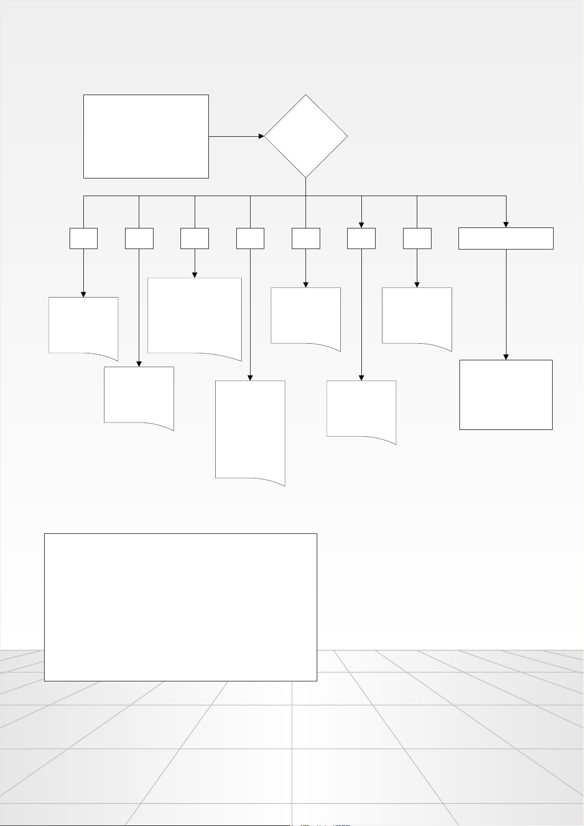
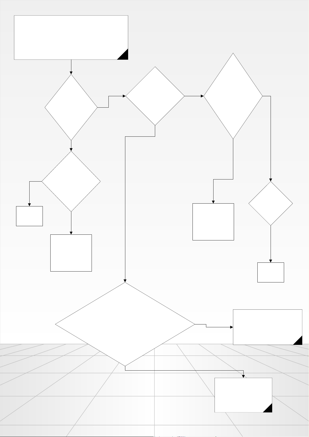
Jump Failure Finding Flow-charts
Check the failure code (Can be
observed at the beginning of
“functional test mode” or “failure
code observing mode”)
100 101110010 001 None111011
Heater always on
NTC short circuit
or open circuit
problem. Follow
“no heating” flow-
chart
Heater open
circuit problem.
Follow “no
heating” flow-chart
problem. Start draining
program. If heating is
observed, change the
electronic card group
Valve triac short
circuit problem.
After checking
wiring(is there a
problem in cable
orders), change
the electronic card
if the valve always
on failure is
actually seen.
Go to the
algorithm
related with the
error code
Pump open circuit
or pump short-
circuit problem.
See no-draining
flow-chart
Water level sensor
Motor triac short-
circuit failure. See
spinning at a
washing step flow-
chart
problem. See no
water filling flow-
chart
Go to the flow-chart
which defines the
problem you observe.
FAILURE CODE OBSERVING MODE
Press the first auxiliary function button from the left for 6 seconds. “Run/
Pause/Cancel” led will start blinking and the program followers will start
blinking as an error code for 3 seconds if any failure routine has run.
After 3 seconds, the machine will return to the selection mode.
After entering the failure code observing mode, pressing and holding “Run/
Pause/Cancel” button for a short time will erase the error code from the
memory. After you complete your inspection, if you are not sure that you
have solved the problem and if you are going to change the electronic card
group, do not erase the error code. For else cases, you may erase the error
Entrance:
Deletion of the error code:
code.
Rev.02 _ 060604 1
Page 2
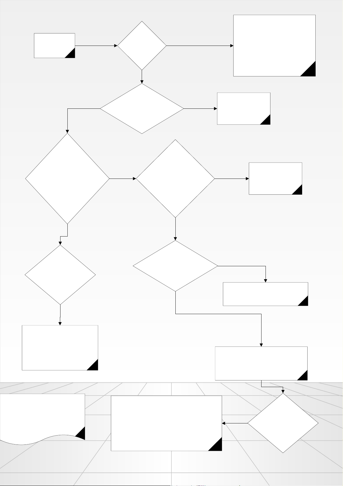
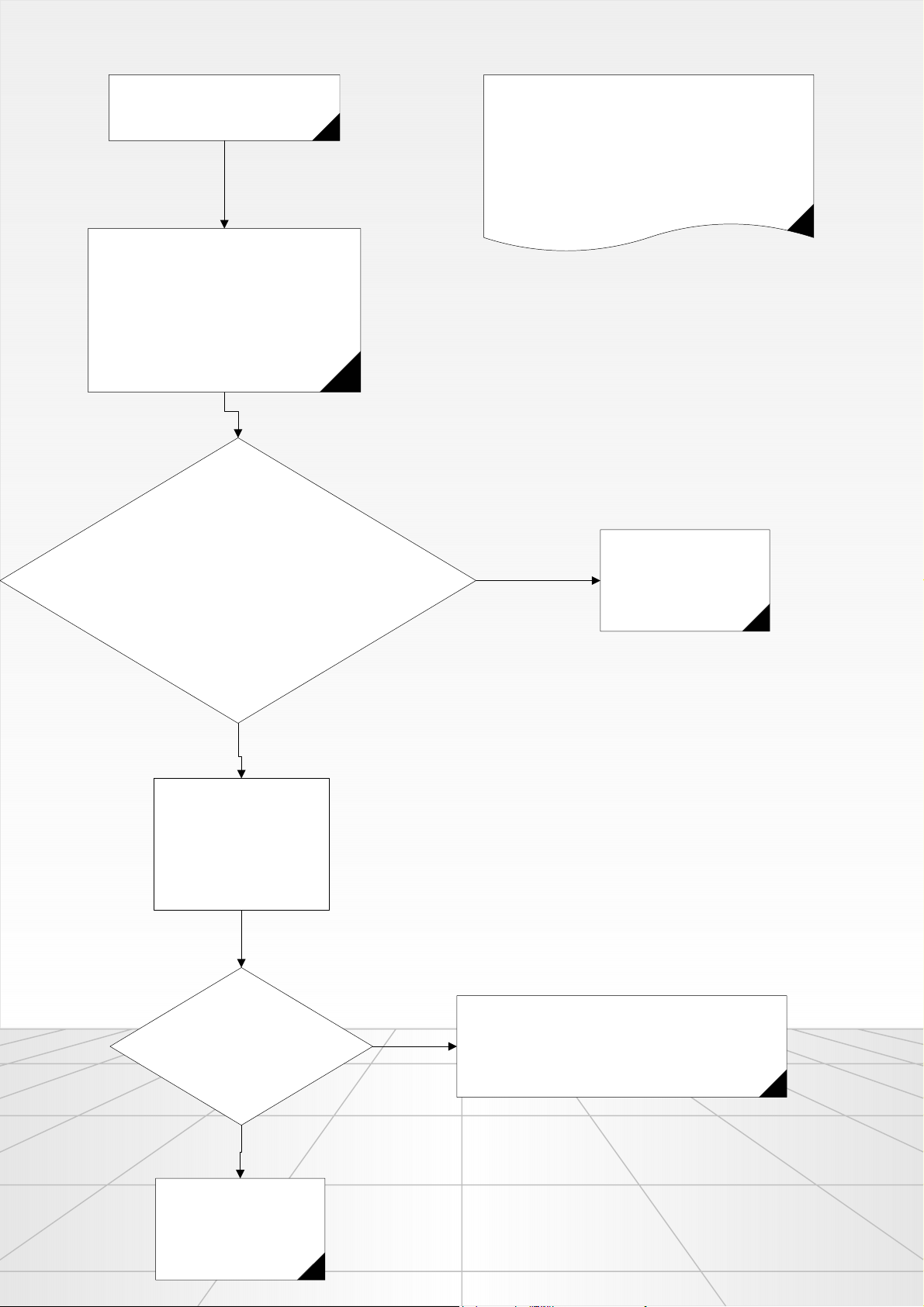
Jump Failure Finding Flow-charts
WM does not work
No
Is “Start/Pause/Cancel” led
illuminating after “Start/Pause/
Cancel” button is pressed.
Is “Ready”
(“door” led in
some models)
blinking
No
Is the door locked?
(If the door is locked, “Ready”
led {“door” led in some models}
No
must be off)
Can you sense the “tact”
feeling of the tact switch
while you press “Start/
Pause/Cancel” button?
Yes
Yes
Check if the program selector is in a
position between two programs. If the
blinking of Ready continues even if
you have seen that the selector is not
in between any adjacent positions,
change the control card group.
See “no water filling”
flow-chart
No
Check if the card is
assembled correctly to
front panel or not.
Yes
Measure the voltage
between the pins 1 and 3 of
door-lock. Is it 230 V AC?
Yes
Change the door-lock
Yes
Measure the voltage between the
pins 1 and 2 of the filter (brown
and blue cables). Is it 230 V AC?
Yes
No
Check the power cord and fuses.
Change the power cord if you see a
problem there.
Check the cable connections of the On/Off.
If there is no problem at the wiring, change
the On/Off switch.
Important Note:
WM does not work failure means, none
of the functions of the machines can be
done. In this condition, WM will not take
any water, will not do any washing,
draining or spinning.
If “Ready” led (“Door” Led in some models) is not
active, door is not locked and 230 V AC is measured
between L and N terminals of the On/Off switch;
change the electronic card group.
Yes
Do you still observe the
problem?
Rev.02 _ 060604 2
Page 3
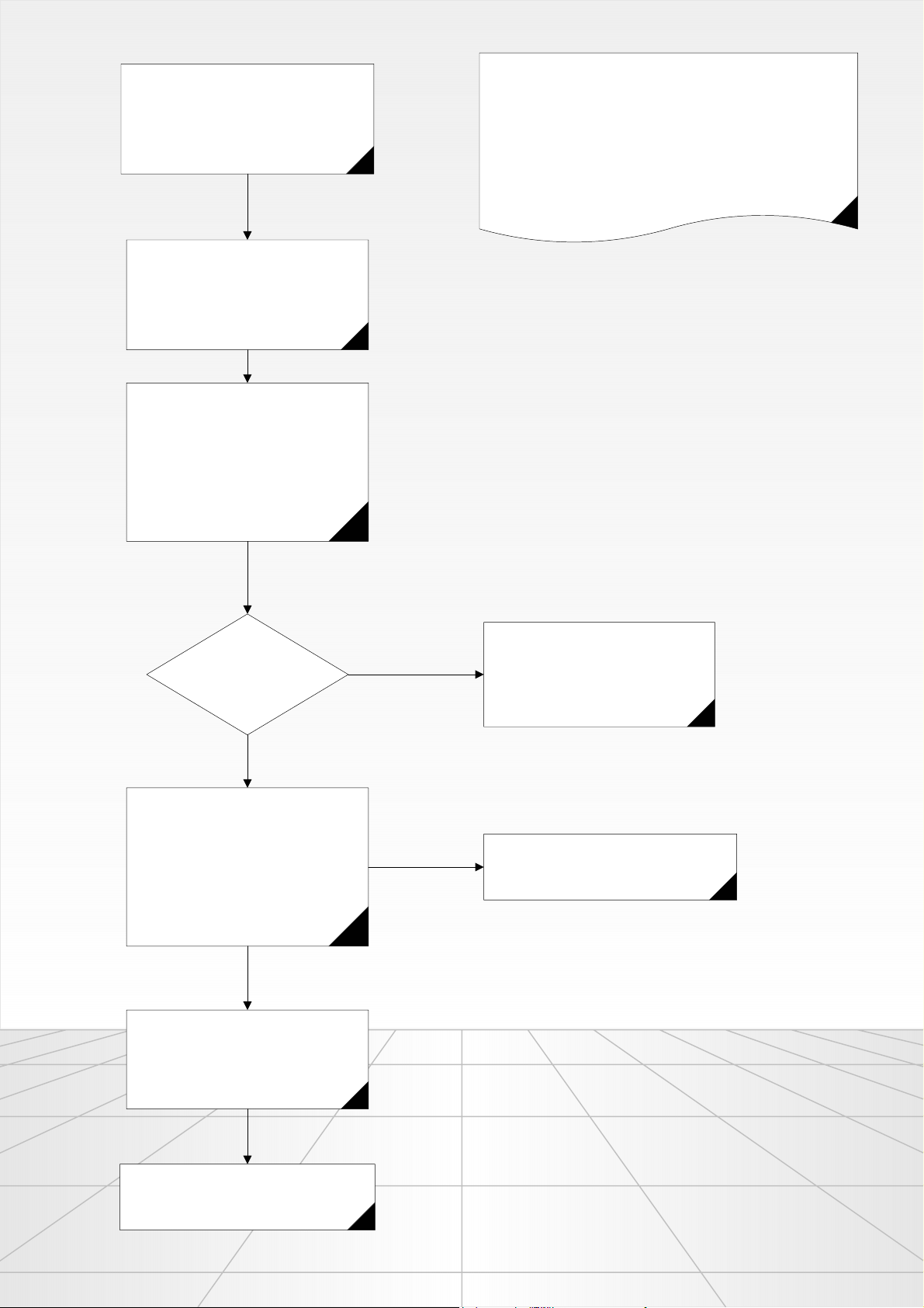
WM does not work.
(There is water filling)
Jump Failure Finding Flow-charts
REMARK
Right after the machine finishes water filling step, if the motor does
non start working or if any motion data is not sensed (Tacho
failures) the electronic card makes 8 take-off trials, waits 120 sec.
between each take-off trial, and if the failure is still detected, the
motor is stopped, and draining starts. Right after draining, the
machine turns to the selection mode.
Make sure the machine completes water
filling step.
Disconnect the J5 and J6 motor
connectors from the main board and
measure the resistance values of motor
windings. Measured vaues must be as
given below:
STATOR IN - COMMUN = 0,5 - 1,5 Ohms
STATOR MP - COMMUN = 0,5 - 1 Ohm
ROTOR1 - ROTOR2 = 0,5 - 1 Ohm
TACHO = 50 - 60 Ohms
Are motor windings OK?
No
First check the motor wiring connections
between the motor and the electronic
card. If there is no problem at the wiring,
change the motor.
Yes
Connect a voltmeter (AC) to J6 (Tacho)
connector on electronic card and rotate
the drum manually. When the drum is
rotating, a voltage value related to the
rotation speed must be seen on the
voltmeter and this walue must be 0V(AC)
when the drum is stopped.
Yes
Make sure that the J5 and J6 connectors
are connected properly to the mainboard.
The terminals of the connector may be
coming out of the plastic body. If there if a
problem at the connector or teminals, try
fixing it.
If the failure still exists, change the electronic
card group.
No
If there is a problem at motor tacho
magnets, change the tacho.
Rev.02 _ 060604 3
Page 4
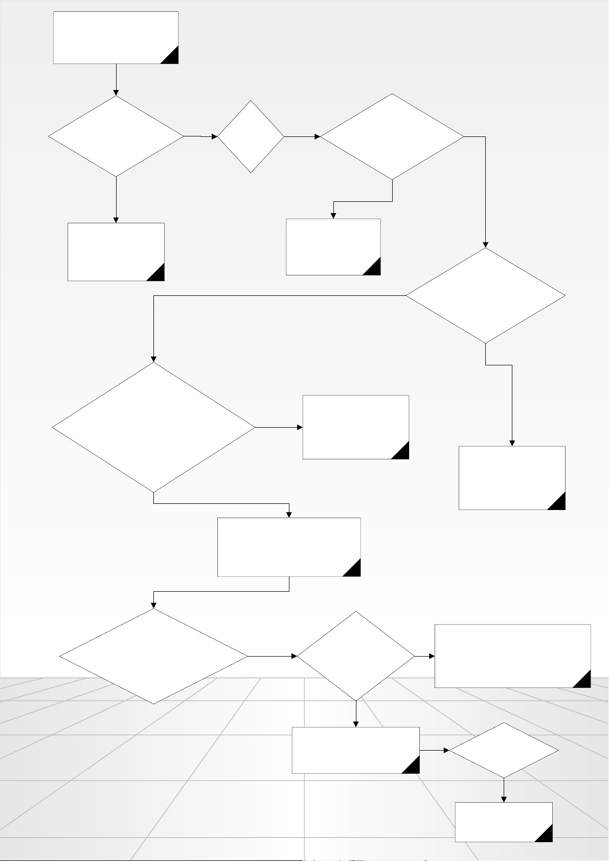
No water filling
Jump Failure Finding Flow-charts
Yes Yes
Is the door locked?
No
See WM does not work
flow-chart
Can you measure 230 V AC between the
terminals of the relevant valve?
Also check the voltage values on J3 and J4
connectors, too.
EVCOLD2 - NEUTRAL=230V (PW)
EVCOLD1 - NEUTRAL =230V (MW)
Is washing
led blinking?
Yes
Open the taps and try
again.
No
Yes
Change the valve
Check if the water taps are
open or not. If they are closed,
open them. Are the taps open?
No
Check the valve filter. Filter may be
congested. Are the filters
congested?
Yes
Check the connections between water
level sensor and the electronic card. Are
the connections OK?
No
Check the wiring between the control
card and the valves.
Yes
Can you measure 5 V
(DC) between the water
level sensors terminals 1
and 2?
Change the water level sensor.
Yes
Change the filter and try
The terminals of the connector on the
No
water level sensor or the electronic card
may not be connecting properly to their
pairs on the wiring. Check the
connections of each pair.
Is the problem solved?
again.
No
Change the electronic
card group.
Rev.02 _ 060604 4
Page 5
Water filling from wrong compartment.
No
Is the failure; water
filling from softener
compartment,
when this is not
expected?
Jump Failure Finding Flow-charts
Is the failure; filling is
done from other
compartment, when it
is expected to be
done from softener
compartment?
Yes
Is there a problem at
J4.2 EVCOLD1-
prewash
and J4.3-EVCOLD2
mainwash
connections? (230 V
AC must be
measured from both
valves terminals.)
230 V AC is
not seen at
least at one
of the pre-
wash and
main wash
terminals.
Yes
Change the
electronic
card
Yes
Measure the voltages
on prewash and
mainwash valves.
Can you measure
230 V AC on both
valve terminals?
No
Change the valve. If
the problem still
exists, chance the
detergent dispenser
assembly.
No, the failure is
not related with
the softener
compartment.
No Problem about
measuring 230 V
(AC) at both valves.
(prewash and
mainwash)
Change the valve. If
the problem still
exists, chance the
detergent dispenser
assembly.
Is there a
problem at
wiring?
No
Change the
electronic
card group
J4.3 EVCOLD2–Prewash valve
Are
J4.2 EVCOLD1–Mainwash valve
J4.1 EVHOT–Hotwater valve
connections made properly?
Yes
No
Check and correct the connections
and test again by starting a washing
program.
Change the control card
Rev.02 _ 060604 5
Page 6
Jump Failure Finding Flow-charts
No heating, heater does not initiate.
Check the NTC connections and wiring. Make
sure the connectors are plugged well.
Also make sure that the water level sensor’s
hose is not punctured or congested.
Remark:
In cases of NTC open / short circuit or heater open circuit,
washing machine performs cold washing without activating
the heater.
Measure the NTC resistance from J2 connector’s NTC-5V terminals. Is
this resistance approximately 4700 Ohms at 25ºC temperature? (The
measurement must be a value different than Open or Short circuit)
NOTE: Before doing the measurement, make sure that the scale
setting of your ohmmeter is set correct.
Yes
Make sure that the heater
wiring and connections are
proper and the connectors
are plugged well. Continue
following the flow-chart if the
problem still exists.
No
Measure the NTC after
seperating it from wiring; If
you measure the NTC as
open or short circuit, change
it.
Unplug one of the heaters connectors
and measure the heater resistance. Is
it about 20-30 Ohms?
Yes
Change the electronic card.
No
Change the heater
Rev.02 _ 060604 6
Page 7
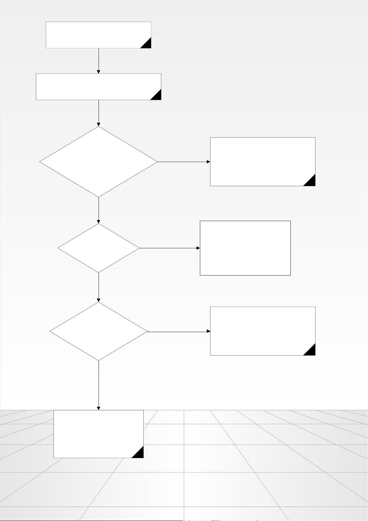
Jump Failure Finding Flow-charts
No Draining
Select Pump program and start the program.
Is the pump active? (can be understanded
by touching the filter cover)
No
Yes
Is the machine filling water?
No
Can you measure 230 V AC voltage
between pump teminals?
Also check J3 connector
PUMP-NEUTRAL voltage. Is it
230V AC ?
Yes
Yes
* Check and Clean the pump filter
* Drain hose level should be between 0,5
and 1 meter from the floor
* Check the drain hose , it ishould not be
banded or broken
If the water temperature in the tub is
higher than 50C, the machine makes
water filling to decrease this
temperature. If the “no draining”
problem still exists after water filling,
check the NTC resistance value.
Pump motor windings are open circuit, change
the pump.
No
Check the wiring and connections
between the electronic card and wires.
Fix if you see any disconnections. If
you don’t see any problem at the wiring
and the connections, change the
electronic card group.
Rev.02 _ 060604 7
Page 8

Jump Failure Finding Flow-charts
WM is spinning at a washing
step.
If the motor triac is short-circuit, motor
will make 2 take-off trials at spinning
step; and pauses 40 sec between these
trials. After these 2 trials the water in the
tub will be discharged by draining.
Un plug the J6 connector and
measure the tacho resistance.
Is it open circuit?
No
Check the wiring and
connections between the
electronic card and J6
connector. Keep following the
flow-chart if the problem still
exists.
Connect a voltmeter (AC) to J6 (Tacho)
connector on electronic card and rotate
the drum manually. When the drum is
rotating, a voltage value related to the
rotation speed must be seen on the
voltmeter and this walue must be 0V(AC)
when the drum is stopped.
Yes
Change the motor. (In tacho open
circuit condition; WM makes 8 trials
and pauses 120 seconds between
each trial. The machine returns to the
selection mode if the tacho resistance
is not normal after these trials.
Are your measurements as
expected above?
No
Change the motor
Yes
Change the electronic card.
Rev.02 _ 060604 8
Page 9

Jump Failure Finding Flow-charts
Program follower LED blinking
Is “Ready” Led
blinking?
No
Yes
Check if the program selector is in a
position between two programs. If the
blinking of Ready continues even if
you have seen that the selector is not
in between any adjacent positions,
change the control card group.
Is “Washing” Led blinking?
Yes
See no water filling flow-chart
Rev.02 _ 060604 9
Page 10

Jump Failure Finding Flow-charts
THE ERROR CODES WHICH CAN BE OBSERVED AT FUNCTIONAL TEST AND FAILURE
H1 : NTC OPEN OR SHORT CIRCUIT ( 100 )
H2 : HEATER OPEN CIRCUIT ( 010 )
H3 : HEATER ALWAYS ON ( 110 )
H4 : VALVE TRIAC SHORT CIRCUIT ( 001 )
H5 : PUMP OPEN OR SHORT CIRCUIT ( 101 )
H6 : MOTOR TRIAC SHORT CIRCUIT ( 011 )
H7 : WATER LEVEL SENSOR FAILURE ( 111 )
CODE OBSERVING MODES
PS : THE ERROR CODES GIVEN ABOVE DOES NOT ALWAYS MEAN REASON FOR THE
FAILURE IS THE DEFINED COMPONENT
ALWAYS CHECK THE CONNECTORS AND WIRING FIRST TO SEE IF THE CAUSE OF
THE FAILURE IS A DISCONNECTION OR SOMETHING SIMILAR.
FAILURE CODE OBSERVING MODE
Press the first auxiliary function button from the left for 6 seconds. “Run/
Pause/Cancel” led will start blinking and the program followers will start
blinking as an error code for 3 seconds if any failure routine has run.
After 3 seconds, the machine will return to the selection mode.
After entering the failure code observing mode, pressing and holding “Run/
Pause/Cancel” button for a short time will erase the error code from the
memory. After you complete your inspection, if you are not sure that you
have solved the problem and if you are going to change the electronic card
group, do not erase the error code. For else cases, you may erase the error
Entrance:
Deletion of the error code:
code.
Rev.02 _ 060604 10
Page 11

Jump Failure Finding Flow-charts
JUMP Functional Test Program
Entrance to the test mode:
1. Turn off the machine from On/Off Button
2. Turn on the W/M from the main switch, while pressing “start/pause/cancel” button. Start icon will start to blink within 3
seconds. At the moment, you can see the code of failure in follower LEDs
3. After seeing the failure, erase the failure by pressing start/pause/cancel button 3 seconds without losing any time
4. After erasing the failure code, you will be in functional test mode. Each push to the start / pause / cancel button will
represent one function.
Functional Test Sequence:
1. All LEDs on the board will start to blink after the door is locked.
2.For the softwares before 32A, 3-6-9 time delay leds will be on in different combinations , related to the spin
potantiometer position.( For max spin 3-9 leds will be on , for no spin no led will be on)
For 32A and following softwares , 1 and 2 auxilary function leds will be on in 4 different combinations, related to the
spin potantiometer position.
3. Take in water from pre-wash compartment
4. Take in water from main wash compartment
5. Take in water from softener compartment (Both PW and MW valves are active)
6. Take in water from main wash compartment if the W/M has a hot valve option (If not this step will be skipped)
7. The heater will be ON. If the water level inside the tub is not enough for the heater to switch on then all valves will be
turn on to fill the level.
8. Clockwise motor rotation with 52 rpm
9. Counterclockwise motor rotation with 52 rpm
10. Draining and after draining is finished spinning up to maximum speed.
11. Turn on all the valves to fill a certain level in a short time for water leakage test on the production line.
12. End
13. You can get off the test mode by turning the WM off.
Rev.02 _ 060604 11
Page 12

COMPONENTS
Mechanical Parts (Dynamic System):
The tub is made of special plastic material that has high strength, is able to decrease
noise level and no corrosion problem. The tub cover is also made of plastic used in
YOÇ and is attached to the tub with special fixing clamps. Truva tub is made of 2
tubs connected each other by PT screw. The main motor is attached to the tub with
two rubber grommets and a bolt in YOÇ series. On the other hand, motors are
connected by 4 arms Positioned behind the tub, on the right, left and top, are
transport security bolt connection slots. There are also two concrete counterbalance
weights one on top of, and one underneath the tub. The tub group is hooked onto the
cabinet at each side by two springs. There are two horizontal shock absorbers at the
bottom, the functions of the springs and the shock absorbers is to dampen the
vibrations caused by tub movement and to reduce motion and noise. The drum is
made of stainless steel.
Shock Absorber System:
Tub group is hooked onto the cabinet at each side by two springs. Furthermore, it is
fixed to the cabinet by two shock absorbers. Springs and shock absorbers defeat
high noise level and the movement of the machine transmitting vibration to the
cabinet. Shock absorbers are connected to chassis and tub with plastic pins instead
of nuts.
Electronic Control and Display Card:
Wash programs, wash and spin motor profiles, protection algorithms and
components (motor, heater, pump, valves, door lock, NTC, pressure sensor, rotary
switch, spin/temperature potentiometer) are controlled by double-phase design
control and display card produced by INVENSYS.
There are connection terminals of smps, motor and other component control circuitstriacs and relays- on the front face of the card. On the other face there are, microchip,
auxillary function and time delay button and led, as well as program follower.
Wash operation is started due to the signals from the auxillary function, time delay,
assembly rotary switch, spin /temperature potentiometer.
Auxillary function, spin/temperature and time delay options can be selected from
electronic card.
Door lock:
A PTC door-lock is used. When the door is closed, the PTC disk is heated up and
locks the door. After the program is terminated, the PTC is cooled down and after
max. 120 seconds the door is unlocked. Thus the door is prevented from opening
during operation. If there is a fault with the door lock, then washing machine will not
operate.
Page 13

Nominal Voltage: 250V 50-60Hz
Current: 10-50mA
PTC Resistance: Min.>=50Ohm
Lock time: <=8sn
Unlock time: 35…70sn
Main motor:
The main motor is a universal series motor. It is controlled by a card. The motor spin
is adjusted as the triggering angle is altered by the triac on the electronic card
module depending on the tachometer. Universal motor is composed of stator and
rotor. Stator and rotor are in series connection by collector and brush. Cycle of the
motor is controlled by electronic card. Motor triac on card adjusts the motor/drum
cycle by changing the triac alert angle according to signals from taco. There is a fuse
that prevents extreme heating of bandage on motor.
Nominal Voltage: 220-240V 50-60Hz
Current: 6A max (wash)/ 3A(spin)
Start Power: 300/450W
Start current: 5…8A(wash)/10A max (spin)
Taco generator technical data:
Number of Double Pole: 8
Taco Voltage at 300rpm: >0,9V
Taco Voltage at 1650rpm: <45V
Heater:
A 1900-watt heater is used. There are two thermofuses on the heater. If the heater
runs without enough water, one of the thermofuse goes off, and thus this heater
cannot be used again. The heater is energized only when there is enough water
inside the washing machine. When the desired temperature is reached, electronic
control card reads the resistance of NTC and if the prescribed resistance (and hence
temperature) is reached, the heater is switched off. In order to prevent the heater
operating without water, “heater safety level” is introduced to microchip. Heater is out
of operation when water level is under the heater level.
Nominal Voltage: 230V 50-60Hz
Nominal Power:1900W (±%5)
Valves:
There are double water inlet valves at single water inlet models and double and
additional single valves at hot water inlet models. Valves are operated by triac.
Nominal Voltage 220-240V 50-60Hz
Nominal Power 5-8W
Coil Resistance 3400-4500 Ohm
Flow Rate 10lt/min
Page 14

Drain Pump:
It is a synchronize motor that has single phased, double pole and magnetic rotor.
Triac runs during drain step. Impedance is protected against the rotor blockage and
continuous operation.
Nominal Voltage 220-240V 50Hz
Resistance 145 Ohm
Current <02A
Flow Rate >14lt/min
Starting Performance <=4sn(160V)
NTC:
As the temperature of the surrounding of NTC increases, its resistance decreases. At
fixed temperature, NTC will always have a specified resistance within the tolerances.
With the aid of this principle it becomes possible to have an operation without using a
mechanical thermo-stop. The heater operates until the desired temperature is
reached. In this way, the selected program completes properly each time in
accordance with the program set and auxiliary functions selection and is nor
influenced by water temperature etc. Thus a considerable time can be saved at low
temperature washes.
No mechanical thermostat or timer is used on these washing machines and the
heater is completely driven by the relay.
Pressure Sensor:
An analog pressure sensor (5V) that gives frequency output is used. At each water
level, the pressure sensor gives a specified frequency output within the tolerances.
With this property of the pressure sensor, it is possible to check and control the water
lever precisely. It is driven by micro.
DISASSEMBLY
1- Top plate:
- Remove two screws that attach the top lid to the body.
- Top plate is pulled back and then upwards and taken off.
2- Back cover:
- Remove five screws that attach the back cover to the body.
- The cover is laid 90º to the body and lifted up and out of its retaining slot.
3-Kickplate:
The plastic screws that attach the kick plate to the body are turned 90º
counter-clockwise and the kick plate unclipped
4-Front panel:
- Door is opened by pulling the handle towards yourself.
- The door hood clamp that fixes the door hood to the front panel is removed
by using the special pliers (shown below) or a suitable alternative.
- The door hood is released from the front panel
Page 15

- Remove two screws that attach the safety lock to the front panel.
- Kick plate is disassembled.
- Remove the screws that attach the front panel to the body.
5-) Front Door (Single Axis):
-Open the front door
-Hinge holder screws, the connection between hinge and front door, are unscrewed
and front door is separated from hinge.
-Hinge holder screws, the connection between hinge and front panel, are unscrewed
and hinge is separated from front panel.
Page 16

External Front Door:
-Screws that connect internal front door to external front door are unscrewed
-External front door is pulled from internal door.
Inner Front Door:
-Disassemble the front door group. Disassemble the subassemblies.
-Collect with the new internal door
External Front Door Glass:
- Disassemble the front door group
- Disassemble the front door
- Separate outer front door glass from the ratchets of internal door
-Assemble new glass (Be careful not to break the ratchets during assembly of the
glass)
Hook:
-Disassemble external front door
-Unscrew 2 screws that hold hook on the internal door
Door Push and Door Push Spring:
-Disassemble the external door.
-Remove the ratchets of door push
Hinge:
-Disassemble the front door.
-Unscrew the 4 screws that connect hinge to the internal door and then remove the
hinge
Page 17

-Assemble the 4 plastic hinge sleeve, taken from the old hinge, to the new hinge.
New hinge is assembly to the internal door.
-Screw the hinge holder to the hinge, screw external door to the internal door.
-Screw front door group to the front panel.
6-) Rotary Switch:
-Push the ratchets of button from the inner face panel and then remove the button.
7-) Drawer panel:
-Drawer is pulled back from the detergent box.
-The piece INDICATED by the arrow is pressed and the drawer is pulled back
-Drawer is turned upside down in order to release the drawer front cover panel
Page 18

8-) Panel
-Drawer is removed from the detergent box
-Remove the screw that attaches the panel to the panel holder
-Remove 2 screws that attach the panel to the panel holder
-Panel is released from the snaps on the panel holder
9-) Program Card:
-Remove the sockets of program control card
-Unscrew the 2 screws of on the display holder
-Separate display holder from ratchets
Page 19

-Unscrew 2 screws and remove on-off switch. Separate the on-off switch from panel
by pushing from lamp holder ratchets.
10-) Program Control Card:
-Remove the card from card holder
11-Pressure Sensor:
- Disassemble front panel
- Remove 2 screws that attach the pressure switch
Page 20

12- On-off Switch (Not Illuminated):
-Disassemble on-off switch cables
-Disassemble 2 PT screws from the switch holder
13-Interference Suppressor:
-Disassembled top plate
-Disconnect interference suppressor cables
-Remove two screws that are in the terminal box behind the body that fixes the
interference suppressor to the terminal group.
-Hold the interference suppressor with one hand and the M8 nut is unscrewed with
an appropriate spanner or socket.
14-Water Inlet Valve
-Disassemble top plate
-Disconnect single valve cables
-Release single valve hose clamp and move up the hose.
-Remove hose from the end of the valve
-Turn the valve counter-clockwise
15-Double Valve:
-Disassemble top plate
-Disconnect double valve cables
-Release single valve hose clamp
-Remove the hose
-Unscrew the 2 screws that connect valve to the cabinet
16-Door Safety lock:
-Hold the front door handle and pull the door towards yourself.
-Remove the clamp that fixes the door hood to the front panel
-Disassemble door hood from the front panel
-Remove two screws that attach the safety lock to the body
-Remove front panel
Page 21

-Disconnect cables
17-Heater:
-Disassemble front panel
-Disconnect heater cables
- Loosen heater M6 bolt and release heater through the tub cover
(When re-fitting the heater ensure element engages correctly in the heater holder clip
which is fixed to the tub)
18-Pump:
-Disassemble front panel
-Disconnect pump cables
-Release tub filter hose from the pump
-Release outlet hose
-Remove the screw that attaches the pump to the body
-Separate pump from the body
Page 22

Connection
hose
Pump cables
Drain hose
connection
Pump screws
19-Tub Gasket:
Disassembling:
-Disassemble front panel
-Grab the door hood and pull with force. The hood and the spring clamp will release
from the tub.
Assembling
-Assembly should be done on the freestanding tub cover. For that reason
disassemble the tub cover by taking out the clips one by one.
-Then find the water drainage hole on the tub gasket. It should be placed at 6 o’clock
position of the tub front cover. Begin from 6 o’clock position and remount the door
hood on the peripheral of the tub opening. Rear tongue should be placed in the tub
side and the front tongue should be placed in the front canal at the same time.
-After positioning the tub gasket, fix it with the spring clamp.
Page 23

20-Water inlet hose:
-Remove front panel
-Loosen the wire clamp on the detergent box connection and release the water inlet
hose
-Pull off the other end of the water inlet hose and release the tub cover by hand.
21- Poly-V Belt:
-Remove back cover
-Pull off Poly-V belt while turning over the pulley
22- Pulley:
-Remove back cover
-Remove poly-V belt
-Unscrew the bat connects the pulley to the drum shaft
-Pull off pulley from the drum shaft.
Page 24

23-Motor:
-Remove back cover
-Plug out motor socket
-Remove poly-V belt
-Unscrew the bolt that attach the motor to the tub (there are 4bolts, in order to
unscrew the bolts use end 40)
-Release motor from the grommet.
24-Power supply cord:
-Release terminal group cover from the snaps at both sides
-Loosen cable holder screw
-Remove power supply cord terminal from the interference suppressor
Page 25

25- Upper counterweight:
-Remove top plate
-Unscrew upper counterweight fixture screws and pull off counterweight
26-Lower Counterweight:
-Disassemble front panel
-Lower counterweight fixture screws are unscrewed and counterweight pulled off.
(Torque value during assembly of lower and upper counterweight should be
2100Ncm)
IMPORTANT:
Transportation bolts should be used in the case of laying the machine to the front
part. Whenever laying of the machine is not required, lower counterweight bolts
should not be screwed.
A 25 Torks end is required in order to separate tub connections.
27-Tub seal:
-Disassemble the front panel
-Loosen the lower counterweight to improve access to tub clips.
-Screw that connects pressure sensor pipe to the tub is unscrewed, so that
unscrewing process becomes easy.
-Remove heater
-Remove NTC
-Release tub cover clips
-Pull off tub cover and turn upside down
-Removed tub seal.
(When re-fitting, ensure that the seal and cover fit into the tub securely. Assembly of
the tub group requires 450Ncm torque with –50Ncm tolerances)
28-Drum group:
-Disassemble front panel
-Remove tub cover
-Disassemble back cover
-Disassemble pulley
-Pull off drum from the tub
Page 26

29-Shock absorber:
-Disassemble back cover
-Pull off damper pin at the tub pressing on the snaps at the sharp end
-Pull off damper pin at the body
30- Outlet hose:
-Remove front panel
-Loosen the clamp at the pump entry of the outlet hose and slid back.
-Pull off outlet hose from the pump
-Release the hose from the snaps at the back of the body
-Release hose from the front of the machine.
 Loading...