

Page 1
REFRIGERATORS AND FREEZERS
Manual for installation, use, and maintenance
Page 2

www.Fagorcommercial.com
REACH-INS OPERATIONAL SERVICE MANUAL / Rev.JUN. 2015
Contents
1 RECEIVING AND INSPECTING THE EQUIPMENT .................................................................................... 3
2 SPECIFICATIONS .................................................................................................................................... 4
3 INSTALLATION ....................................................................................................................................... 6
3.1 UN CRATING .................................................................................................................................. 6
3.2 LOCATION ...................................................................................................................................... 6
3.3 DATA PLATE ................................................................................................................................... 7
3.4 INSTALLATION OF CASTORS OR OPTIONAL LEGS .......................................................................... 7
3.5 LEVELING ....................................................................................................................................... 9
3.6 ELECTRICAL CONNECTIONS ........................................................................................................... 9
3.7 SHELVING INSTALLATION ............................................................................................................ 10
4 OPERATION ......................................................................................................................................... 10
4.1 ELECTRONIC CONTROL ................................................................................................................ 10
4.2 OTHER FUNCTIONS ..................................................................................................................... 14
5 MAINTENANCE .................................................................................................................................... 17
5.1 Stainless Steel Care and Cleaning ............................................................................................... 17
5.2 Cleaning the Condenser Coil ....................................................................................................... 17
5.3 GASKET ........................................................................................................................................ 18
5.4 DOORS/HINGES ........................................................................................................................... 18
5.5 DRAIN .......................................................................................................................................... 19
6 TROUBLE SHOOTING ........................................................................................................................... 20
7 WIRING DIAGRAMS ............................................................................................................................. 21
8 WARRANTY.......................................................................................................................................... 25
PAGE 2
Page 3

www.Fagorcommercial.com
REACH-INS OPERATIONAL SERVICE MANUAL / Rev.JUN. 2015
1 RECEIVING AND INSPECTING THE EQUIPMENT
Up on receiving your new Fagor Refrigerator, check the package and the machine for any
damages that may have occurred during transportation. Visually inspect the exterior of the
package. I f damaged, open and inspect the contents with the carrier. Any damage should be
noted and reported on the delivering carrier’s receipt.
In the event that the exterior is not damaged, yet up on opening, there is concealed damage to
the equipment notify, the carrier immediately. Notification should be made verbally as well as
in written form. Request an inspection by the shipping company of the damaged equipment.
Retain all crating material until inspection has been made. Contact the dealer through which
you purchased the unit.
Check the compressor compartment thousing and visually inspect the refrigeration package.
Be sure lines are secure and base is still intact.
A NOTE FROM OUR QUALITY CONTROL MANAGER
CONGRATULATIONS ON YOUR NEW PURCHASE. WE WOULD LIKE TO WELCOME
YOU TO THE FAGOR TEAM. THE UNIT IN FRONT OF YOU IS A GREAT PIECE OF
EQUIPMENT THAT WILL BECOME ONE OF YOUR MOST RELAIBLE TOOLS IN YOUR
DAILY OPERATIONS FOR YEARS TO COME!
PRIOR TO SHIPPING YOUR UNIT, OUR TRAINED SERVICE TECHNICIANS TESTED
YOUR UNIT FOR A PERIOD OF 12 HOURS. THIS PERFORMANCE TEST WAS
RECORDED AND A COPY OF THE RESULTS IS INCLUDED WITH THIS SERVICE
MANUAL. DURING THIS TEST, OUR HIGHLY QUALIFIED PERSONNEL INSPECTED
YOUR MACHINE FOR LEAKS, LOSE COMPONENTS,AND IMPROPER NOISE LEVELS.
WE ALSO TESTED THE COOLING PERFORMANCE IN AN EFFORT TO GIVE YOU THE
BEST AND MOST RELAIBLE UNIT POSSIBLE.
PAGE 3
Page 4
www.Fagorcommercial.com
REACH-INS OPERATIONAL SERVICE MANUAL / Rev.JUN. 2015
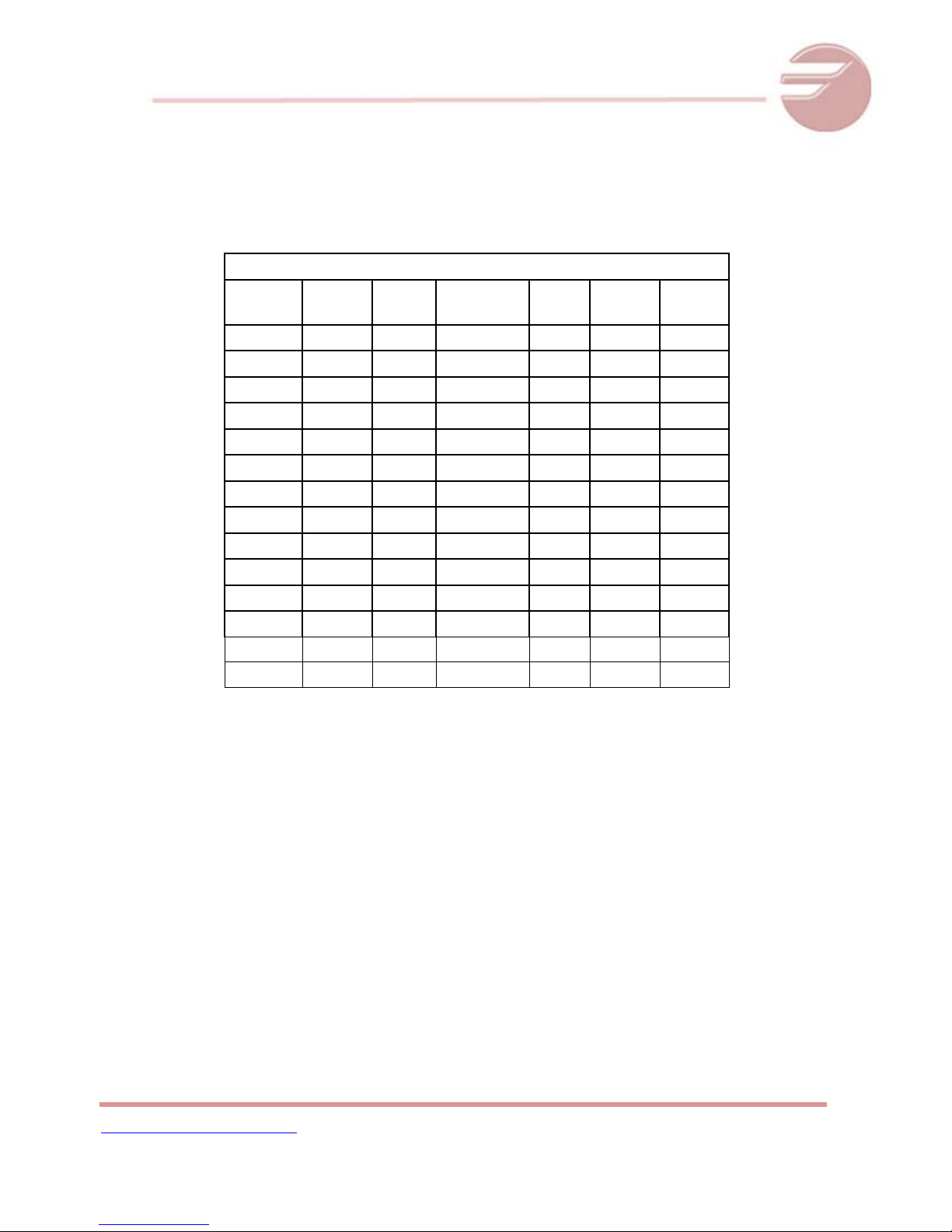
REACH IN REFRIGERATORS AND FREEZERS, GENERAL SPECS
Model
Capac.
(Cu.Ft.)
# of
Shvls
BTU'S/Hr
Charge
Onz.
Ref.
Ship
Weight
QR-1
23 3 1666
11.3
R-134a
295
QR-2
49 6 2104
13.4
R-134a
475
QF-1
23 3 2493
16.6
R-404A
295
QF-2
49 6 3644
21.5
R-404A
475
QR-1G
23 3 1666
11.3
R-134a
295
QR-2G
49 6 2104
13.4
R-134a
475
QVR-1
21 3 1666
11.3
R-134a
295
QVR-2
45 6 2104
13.4
R-134a
475
QVF-1
21 3 2493
16.6
R-404A
295
QVF-2
45 6 3644
21.5
R-404A
475
QVR-1G
21 3 1666
11.3
R-134a
295
QVR-2G
45 6 2104
13.4
R-134a
475
QVR-3
72 9 -
22.2
R-404A
-
QVF-3
72 9 -
16.6
R-404A
-
2 SPECIFICATIONS
PAGE 4
Page 5
www.Fagorcommercial.com
REACH-INS OPERATIONAL SERVICE MANUAL / Rev.JUN. 2015
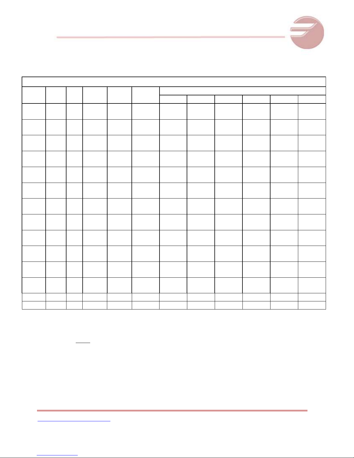
REACH IN REFRIGERATORS AND FREEZERS, ELECTRICAL SPECS
Model
Max.
Amps
HP
Voltage
NEMA
Plug
Breaker
Size*
Wire gauge recommended for 2% voltage drop in supply circuits **
40 ft ***
60 ft
80 ft
100 ft
120 ft
140 ft
QR-1
5.6
3.1
1/4
115
220
5-15P
2P+TT
15 amp
10 amp
14 AWG
14 AWG
14 AWG
14 AWG
12 AWG
14 AWG
12 AWG
14 AWG
12 AWG
14 AWG
10 AWG
12 AWG
QR-2
6.9
3.5
1/3
3/8
115
220
5-15P
2P+TT
15 amp
10 amp
14 AWG
14 AWG
12 AWG
14 AWG
12 AWG
14 AWG
10 AWG
12 AWG
10 AWG
12 AWG
10 AWG
12 AWG
QF-1
8.5
4.5
3/4
115
220
5-15P
2P+TT
15 amp
10 amp
14 AWG
14 AWG
12 AWG
14 AWG
10 AWG
12 AWG
10 AWG
12 AWG
8 AWG
12 AWG
8 AWG
12 AWG
QF-2
12.9
6.5 1
115
220
5-15P
2P+TT
20 amp
10 amp
12 AWG
14 AWG
10 AWG
12 AWG
8 AWG
12 AWG
8 AWG
12 AWG
8 AWG
12 AWG
6 AWG
12 AWG
QR-1G
6
3.4
1/4
115
220
5-15P
2P+TT
15 amp
10 amp
14 AWG
14 AWG
14 AWG
14 AWG
12 AWG
14 AWG
12 AWG
14 AWG
10 AWG
12 AWG
10 AWG
12 AWG
QR-2G
7.3
3.9
1/3
115
220
5-15P
2P+TT
15 amp
10 amp
14 AWG
14 AWG
12 AWG
14 AWG
12 AWG
14 AWG
10 AWG
12 AWG
10 AWG
12 AWG
8 AWG
12 AWG
QVR-1
5.6
3.1
1/4
115
220
5-15P
2P+TT
15 amp
10 amp
14 AWG
14 AWG
14 AWG
14 AWG
12 AWG
14 AWG
12 AWG
14 AWG
12 AWG
10 AWG
12 AWG
QVR-2
6.9
3.5
1/3
3/8
115
220
5-15P
2P+TT
15 amp
10 amp
14 AWG
14 AWG
12 AWG
14 AWG
12 AWG
14 AWG
10 AWG
12 AWG
10 AWG
12 AWG
10 AWG
12 AWG
QVF-1
8.5
4.5
3/4
115
220
5-15P
2P+TT
15 amp
10 amp
14 AWG
14 AWG
12 AWG
14 AWG
10 AWG
12 AWG
10 AWG
12 AWG
8 AWG
12 AWG
8 AWG
12 AWG
QVF-2
12.9
6.5
1
115
220
5-15P
2P+TT
20 amp
10 amp
12 AWG
14 AWG
10 AWG
12 AWG
8 AWG
12 AWG
8 AWG
12 AWG
8 AWG
12 AWG
6 AWG
12 AWG
QVR-
1G
5.9
1/4
115
5-15P
15 amp
14 AWG
14 AWG
12 AWG
12 AWG
10 AWG
10 AWG
QVR-
2G
7.3
3.9
1/3
3/8
115
220
5-15P
2P+TT
15 amp
10 amp
14 AWG
14 AWG
12 AWG
14 AWG
12 AWG
14 AWG
10 AWG
12 AWG
10 AWG
12 AWG
8 AWG
12 AWG
QVR-3
11.5
3/4
115
5-15P
15 amp
14 AWG
12 AWG
12 AWG
10 AWG
10 AWG
8 AWG
QVF-3
16.0
3/4
115
5-15P
15 amp
14 AWG
12 AWG
12 AWG
10 AWG
10 AWG
8 AWG
Note:
*Breaker sizes are recommended to protect the equipment by overload; this
breaker only must be dedicated for the equipment.
**If the equipment is installed faraway of the circuit breaker, these are the
wire gauge recommend to connect the appliance; if the distance is higher that
the chart values, please contact an electrician.
***Distance in feet from the breaker or the power supply to the appliance.
PAGE 5
Page 6

www.Fagorcommercial.com
REACH-INS OPERATIONAL SERVICE MANUAL / Rev.JUN. 2015
3 INSTALLATION
3.1 UN CRATING
Remove the outer packaging. Cut the 4 clamps that hold the refrigerator to the skid. Lift the unit off
the skid.
If machine was laid down during this operation, remember to leave the cabinet up
right for 24 hours before connecting to power source.
3.2 LOCATION
Units represented in this manual are intended for indoor use only. Be sure the location chosen has a
floor strong enough to support the total weight of the unit and its contents. For the most efficient
operation, be sure to provide at least three (3) inches between sides, back and top of the unit.
THE MACHINES NEEDS TO BE INSTALLED 2 FEET AWAY FROM ANY HEAT SOURCES.
The unit should not be installed under ambient temperatures higher than 100 °F.
If the relative humidity is higher than 60 %, the door frames may sweat water. This is not a
malfunctioning of the unit.
WARNING
The following actions will void your warranty:
-Modification of power cord.
-Connecting the unit to any extension cord.
-Neglecting to install the castors or optional legs.
Inside cabinet:
The first cleaning must happen when you unpack the unit and before it is turned ON. For this, you
have to clean the unit with warm water and mild detergent. When it is cleaned and dry, proceed to
install accessories and plug your unit into a dedicated outlet. WAIT 24 HOURS BEFORE PLACING
PRODUCT IN THE UNIT. This will guarantee that it is working properly. Consequential damages are
not covered under warranty.
PAGE 6
Page 7
www.Fagorcommercial.com
REACH-INS OPERATIONAL SERVICE MANUAL / Rev.JUN. 2015
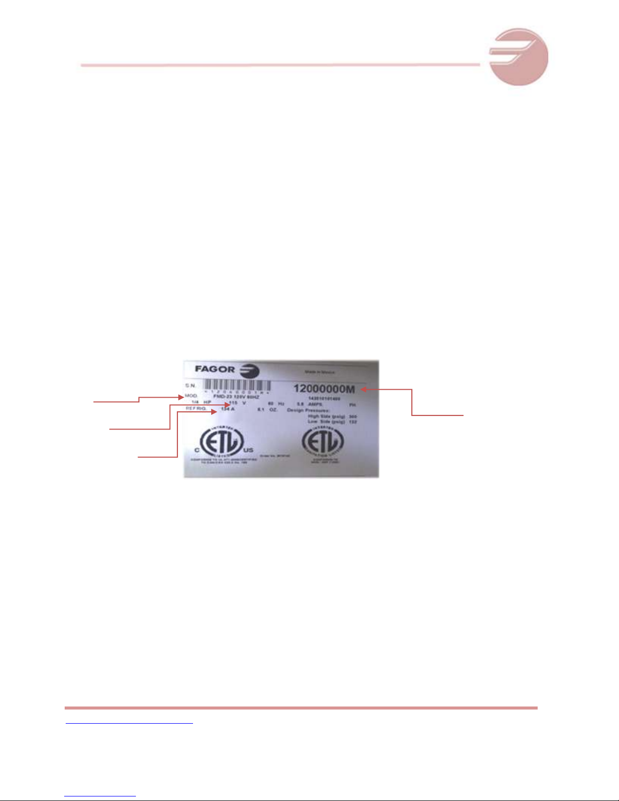
Model
Electrical
Refrigerant Type
SERIAL NUMBER FOR
THE EQUIPMENT
(8 digits and ends in
“M”)
Outside cabinet:
Be sure that the unit has access to ample air to breathe. Avoid hot corners and locations near stoves
and ovens. It is recommended the unit be installed no closer than 3” from any wall. The place where
the refrigerator is placed must be open and clean. This will reduce the amount of debris and dirt on
the condenser fan and coil.
3.3 DATA PLATE
The data plate is located inside the cabinet, near the top front, left corner. Under no circumstances
should the data plate be removed from the unit. The data plate is essential to identify the particular
features of your machine and i t is of great benefit to installers, operators, and maintenance
personnel. It is recommended that, in the event the data plate is removed, you copy down the
essential information in this manual for reference before installation. Removal of data plate will void
the warranty.
3.4 INSTALLATION OF CASTORS OR OPTIONAL LEGS
To obtain maximum strength and stability of the unit, be sure that castors are secure and unit is level.
Inside the unit you will find a Castor kit which includes: four castor wheels, leveling shims, and
assembly tool.
Installation of castors:
Cut the 4 straps that hold the refrigerator to the pallet.
PAGE 7
Page 8

www.Fagorcommercial.com
REACH-INS OPERATIONAL SERVICE MANUAL / Rev.JUN. 2015
Slide out unit until castor holes are exposed. CASTORS WITH BRAKES MUST BE INSTALLED IN THE
FRONT OF THE UNIT
Carefully, lift the unit high enough to install the casters.
Repeat the same operation to install the remaining castors.
CAUTION! NEVER LAY MACHINE ON ITS BACK! IF NEEDED, LEAVE THE CABINET UP RIGHT FOR 24
HOURS BEFORE CONNECTING TO POWER SOURCE. TO AVOID DAMAGE TO LOWER FRAME, SLOWLY
RAISE UNIT TO UP RIGHT POSITION
FAILURE TO MEET THIS REQUIREMENT CAN CAUSE COMPRESSOR FAILURE AND UNIT DAMAGE. THIS
WILL NOT BE COVERED UNDER WARRANTY!
For leveling, insert shims between the castor and the frame rail. Install the desired number of shims.
Make sure the slot of the shim is in contact with the threaded stem of the castor.FIG.2
If more than one shim is used, turn the slot of the shim approximately 90 angles. If shims are installed
in line, they may slip out.
Turn the bearing race clockwise to tighten and secure the castor. Use provided tool to secure all
castors properly.FIG.3
FIG.1 FIG.2 FIG.3
Optional legs are hand-tightened. Thread leg into cabinet bottom frame rail. The end of the leg is
adjustable for easy leveling.
Caution! To avoid damage to lower rail assembly, slowly raise unit to upright position
Caution! When lifting unit remember to leave the cabinet up right for 24 hours before plugging into
power source. Failure to meet this requirement can cause compressor failure and unit damage.
PAGE 8
Page 9

www.Fagorcommercial.com
REACH-INS OPERATIONAL SERVICE MANUAL / Rev.JUN. 2015
3.5 LEVELING
Set unit in its final location. A level cabinet looks better and will perform better. Effective condensate
removal and door operation will be effected by leveling. Machine must be leveled front to back and
side to side with a level tool. Castors k i t w i l l include shims for leveling. Insert the shim between the
castor and the frame rail. (See installation of castors). Lock front castors so cabinet does not move.
Ensure drain hose is inside drain pan.
3.6 ELECTRICAL CONNECTIONS
Refer to the amperage data in this manual, or on data plate, and your local code or the National
Electrical Code to be sure unit is connected to the proper power source. Verify correct incoming
voltage according to the Data Plate information.
Do not, under any circumstances, cut or remove the ground prong from the power cord. Fagor units
must be properly grounded.
NEVER USE AN EXTENSION CORD! Fagor will not warranty any unit that has been
connected to an extension cord.
Fagor equipment must be grounded and connected in accordance with NEC Article 422Appliances.
DANGER:
Power must be turned off and disconnected from the power source whenever performing
maintenance, repair or cleaning the condensing unit.
If machine is still running when power is off, disconnect power at the circuit breaker before
unplugging the machine.
WARNING:
Machine and compressor warranties are void if failure is due to improper electrical
PAGE 9
Page 10

www.Fagorcommercial.com
REACH-INS OPERATIONAL SERVICE MANUAL / Rev.JUN. 2015
installation.
3.7 SHELVING INSTALLATION
Hook shelf rails onto shelf pilasters
Position all shelf rails equal in distance from the floor for level shelves
Wire shelves are oriented so that cross support bars are facing down
Note: Single door Reach-in include an air flow guard on the rear of the shelves as well as a lip to
maintain an air space at the rear of the cabinet
Place shelves on shelf clips, making sure all corners are seated properly
4 OPERATION
4.1 ELECTRONIC CONTROL
After connecting your unit, turn ON rocker switch located next to the controller. The display will light
up showing the temperature inside the unit. Also, the compressor and fan icons will flash for a period
of three minutes. After this delay the unit will start cooling.
Compressor Icon
Evaporator Fan Icon
Temperature inside the cabinet
Verify you don't have any alarms on the temperature controller. If after you turn ON the equipment
the controller shows the alarm icon or an error code, call f o r technical service. They will help you fix
the problem.
Note: The controller on the equipment is programmed to display internal temperatures in Fahrenheit (°F). To change to
Celsius (°C), see point 4.2
PAGE 10
Page 11

www.Fagorcommercial.com
REACH-INS OPERATIONAL SERVICE MANUAL / Rev.JUN. 2015
PAGE 11
Page 12

www.Fagorcommercial.com
REACH-INS OPERATIONAL SERVICE MANUAL / Rev.JUN. 2015
Description of Buttons on the Controller
To increase Set Point of
Temperature
To turn t h e u n i t ON/OFF
without
unplugging the equipment (press
and hold 3 seconds)
To Change the set point
To access programming mode
To decrease Set Point of
Temperature
To set a manual defrost (press and
hold
3 seconds)
Changing the set point of the temperature on the controller
The unit comes with a factory default set point (-8°F Freezers, 32°F Refrigerators). These set
values will make the unit perform at its maximum capacity. Therefore, it is not recommended
to change the set point. If set point needs to be changed, follow the next steps.
Note:
If you change the set point of temperature, the performance of the equipment will change. Cha n ges ma d e in
th e parame t ers of t h e control ler will not be covered under warranty.
1. Push the SET button for one (1) second. You should see a flashing number. Release the
button.
PAGE 12
Page 13

www.Fagorcommercial.com
REACH-INS OPERATIONAL SERVICE MANUAL / Rev.JUN. 2015
For Refrigerators
EZY Value
Application
Temperature in °F
3
Refrigeration
Temperature in °C
4
Refrigeration
For Freezers
EZY Value
Application
Temperature in °F
1
Freezer
Temperature in °C
2
Freezer
Temperature in °F
3
Refrigeration
Temperature in °C
4
Refrigeration
2. Press the up and down arrows to increase or decrease the set temperature. Then press
the set button to save the new set point.
Note:
The maximum value you can set in the controller is: For refrigerators: 5°C (40°F)
For freezers: -16°C (2°F)
3. If you wish decrease the value of the set point for a new temperature, press the button
DOWN arrow (see the picture below). Press this button to reach the desired value.
Release the button and then press the SET button to keep, and save, the new value.
Note:
The minimum value you can set in the controller is: For refrigerators: -1°C (30°F)
For freezers: -23°C (-8°F)
Changing the reading temperature from °F to °C
To change the reading of the temperature from °F to °C or vice versa, you need access to the
programming mode in the controller. To do this, press and hold the SET button for five (5)
seconds until “PS” is shown in the display. Release the button and press the SET button one
time. Now you will see the number zero (0). With the button UP arrow, set a value of “22” and
then press the SET button. You will see the “PS” again. Use the button DOWN arrow to find
the parameter “EZY” and press the SET button one time. Using the UP or DOWN button set a
value according to the chart below.
Note:
PAGE 13
Page 14

www.Fagorcommercial.com
REACH-INS OPERATIONAL SERVICE MANUAL / Rev.JUN. 2015
Freezer equipment can be used like a refrigerator by selecting the value of the parameter “EZY” according to the
chart above. Refrigerators must never be used like a freezer.
After you chose the value for the “EZY” parameter, press and hold the SET button for 5
seconds. You will see the temperature on the display in °F or °C according to your selection.
4.2 OTHER FUNCTIONS
Manual Defrost
To select manual defrost, hold the button DOWN arrowfor5seconds. The snowflake icon will
appear on the display. When this icon is solid it indicates that the equipment is in Defrost
mode.
To exit manual defrost, hold the D O WN button arrow for 5 seconds. The snow flake icon will
turn off. Wait 2 minutes for the compressor to start.
Note:
If the equipment doesn’t reach the temperature, first verify that the defrost cycle is not ON.
The unit will go into defrost every six hours for an average of 20 minutes. The defrost cycle is time initiated and
temperature terminated.
NOTE!
Good air flow inside the cabinet is critical. Do not block air flow to the fans. Allow three inches
of space along the front, back, and sides.
CAUTION!
Do not introduce hot foods, chemical or corrosive products, drugs, or
open beverage bottles.
The unit must run for at least 24 hours before any product is placed inside. Failure to do so
may ice up the evaporator coil. Consequently, the unit will never reach the desired set point.
This failure will not be covered under warranty.
PAGE 14
Page 15

www.Fagorcommercial.com
REACH-INS OPERATIONAL SERVICE MANUAL / Rev.JUN. 2015
CAREL CONTROL (IR33+)
The operating parameters can be modified using the front keypad. Access differs depending on the type:
set point, frequently-used parameters (F) and configuration parameters (C). The type of parameter is
specified in the table of parameters. Access to the configuration parameters is protected by a password
for the configuration parameters that prevents unwanted modifications or access by unauthorised
persons. The password can be used to access and set all the control parameters.
Setting the set point
To change the set point St (default -8°C)
• Press Set for more than 1 s: the display shows Set and then the current value of St;
• press UP/DOWN until reaching the desired value;
• press Set to save the new value of St.
Setting type F parameters
Type F parameters include the set point, differential, temperature monitoring interval, interval between
defrosts, end defrost temperature, dripping time, alarm thresholds, alarm bypass times, etc. See the
parameter table.
Procedure:
1. Press Prg/Mute one or more times to return to the standard display;
2. Press Prg/Mute for more than 3 seconds (if an alarm is active, the Buzzer is muted): the
display will show the code PS (Password) and The number 0;
3. Press Set, the display shows parameter St;
4. Press UP or DOWN until reaching the desired parameter: when Scrolling, an icon is displayed
that represents the category the Parameter belongs to (see the table below and the
parameter table);
5. Press Set to display the value of the parameter;
6. Press UP/DOWN until reaching the desired value;
7. Press Set to temporarily save the new value and display the parameter Code again;
8. Repeat steps 4) to 7) to set other parameters;
9. To permanently save the new values of the parameters, press Prg/ Mute for 5 seconds. This
exits the parameter setting procedure.
PAGE 15
Page 16

www.Fagorcommercial.com
REACH-INS OPERATIONAL SERVICE MANUAL / Rev.JUN. 2015
Setting type C parameters
Type C parameters include the type F parameters plus all the other control parameters.
Procedure:
1. Press Prg/Mute one or more times to return to the standard display;
2. Press Prg/Mute for more than 3 seconds (if an alarm is active, the Buzzer is muted): the
display will show the code PS (Password) and The number 0;
3. Press UP/DOWN and enter the password: 22. Press Set, the display Shows parameter/2;
4. Press UP or DOWN until reaching the desired parameter: when Scrolling, an icon is displayed
that represents the category the Parameter belongs to (see the table below and the
parameter table);
5. Press the SET button to display the value of the parameter;
6. Press UP/DOWN until reaching the desired value;
7. Press Set to temporarily save the new value and display the parameter Code again;
8. Repeat steps 4) to 7) to set other parameters;
9. To permanently save the new values of the parameters, press Prg/Mute for 5 seconds. This
exits the parameter setting procedure.
Important:
• If the controller is powered down before pressing Prg/mute, all the changes made to the
parameters will be lost;
• In the two parameter setting procedures (F and C), the new values are only saved after having
pressed Prg/mute for 5 seconds. When setting the set point, the new value is saved after
confirming with Set.
IF YOU NEED MORE INFORMATION PLEASE CONTACT THE TECHNICAL SUPPORT
PAGE 16
Page 17

www.Fagorcommercial.com
REACH-INS OPERATIONAL SERVICE MANUAL / Rev.JUN. 2015
5 MAINTENANCE
5.1 Stainless Steel Care and Cleaning
Proper cleaning of stainless steel requires soft cloths or plastic scouring pads. Never use steel
pads, wire brushes, or scrapers!
Cleaning solutions need to be alkaline or non-chloride cleaners. Any cleaner containing
chlorides will damage the protective film of the stainless steel. Chlorides are commonly found
in hard water, salts, house hold and industrial cleaners. If a cleaner containing chloride is used,
be sure to rinse repeatedly and dry thoroughly up on completion.
Stainless steel must be cleaned every day with soap and water. Extreme stains or grease
should be cleaned with a non-abrasive cleaner and plastic scrub pad. When using a stainless
steel chemical cleaner, make sure it is recommended for commercial applications.
Never use an acid based cleaning solution! Many food products have an acidic content which
can deteriorate the stainless steel finish. Be sure to clean ALL food products from any stainless
steel surface. Failure to do so, will result in spots and rust on the surface affected.
5.2 Cleaning the Condenser Coil
DANGER: Power must be turned off and disconnected from the power source whenever
performing maintenance, repair or cleaning the condensing unit.
Disconnect machine. Remove front bottom panel and carefully slide out the condensing unit.
The condenser coil requires regular cleaning. It is recommended every 30-60 days, depending
on the accumulation of dust and grease.
If the build upon the coil consists of only light dust and debris, the condenser coil can be
cleaned with a simple brush. Heavier dust build up may require a vacuum or even compressed
air to blow though the condenser coil.
If heavy grease is present, there are de-greasing agents available for coils. The condenser coil
may require to be sprayed with de-greasing agent and then to be dried with compressed air.
Be sure all electrical and mechanical parts are dry before turning ON the power.
PAGE 17
Page 18

www.Fagorcommercial.com
REACH-INS OPERATIONAL SERVICE MANUAL / Rev.JUN. 2015
Never use high pressure water for cleaning the condenser coil. Water can damage the
electrical components located near or at the condenser coil. Do not place filter material in
front of condenser coil. This material blocks air-flow to the coil similar to having a dirty coil!
If you keep the Condenser clean, you will minimize your service expense and lower your
electrical costs. Failure to maintenance clean condenser coil can initially cause high
temperatures and excessive run times. Continuous operation with dirty or clogged condenser
coils can result in compress or failures. This will not be covered under warranty.
Neglecting the condenser coil cleaning procedures WILL VOID YOUR WARRANTY
To put back the condensing unit, slide in the unit carefully in. BE SURE THE DRAIN PIPEIS
LOCATED OVER THE DRAIN PAN. Replace front bottom panel.
5.3 GASKET
Gaskets require regular cleaning to prevent mold and mildew build up and to keep the
elasticity of the gasket. Gasket cleaning can be done with the use of warm soap and water.
Avoid the use of chemical cleaning products on gaskets as this can cause them to become
brittle and prevent proper sealing. Also, never uses hard tools or knives to scrape or clean the
gasket which could possibly tear the gasket and rip the bellows.
Gaskets can easily be replaced and do not require the use of tools or authorized service
personnel. To remove the gasket, pull the gasket towards you. To replace gasket, press the
gasket against the groove of the door the gasket will “snap” back into place.
5.4 DOORS/HINGES
During transportation the doors hinges may become loose. If the door(s) don’t look aligned,
tighten the screws that hold the hinge brackets to the frame of the unit. If the doors are loose
or sagging, this can cause the hinge to pull out of the frame which may damage the doors and
the door hinges. In some cases, this fix or adjustment may require a qualified service agent or
maintenance personnel.
PAGE 18
Page 19

www.Fagorcommercial.com
REACH-INS OPERATIONAL SERVICE MANUAL / Rev.JUN. 2015
5.5 DRAIN
Each unit comes equipped with a drain pan located outside the unit. The drain pan catches the
condensation produced inside the evaporator coil. If the drain hose become loose or
disconnected from moving or bumping the unit, you may find a puddle of water inside/outside
of the unit. Replace or fix any lose connections. IF YOU NOTICE EXCESSIVE WATER
ACCUMULATION ON THE INSIDE OF THE UNIT, be sure the drain tube is connected firmly and
not kinked or bent. It is the owner’s responsibility to maintain the drain pan leveled, and with
the drain hose inside of the pan.
Units installed in a humid environment will produce large amounts of water in
the drain pan. This is NOT a malfunction of the unit. It is the customer’s
responsibility to clear the drain pan as necessary to avoid puddles of water
underneath the unit.
Do not store open containers with liquids inside the unit. This will increase the
amount condensation inside and outside of the unit, and the evaporator coil
will freeze up.
Do not store hot products inside the unit. This will increase the amount of
condensation inside and outside of the unit, and the evaporator coil will freeze
up.
The unit must be level and on a strong surface .When moving the unit, check
the drain piping to make sure it was not disconnected or moved out of the
drain pan. This will not be covered under warranty
PAGE 19
Page 20

www.Fagorcommercial.com
REACH-INS OPERATIONAL SERVICE MANUAL / Rev.JUN. 2015
6 TROUBLE SHOOTING
Follow the next steps before requesting warranty service. Failure to do so, may
result in service charges for you and may void your warranty:
1) Refrigerator doesn’t work:
a. Check that the machine is still connected.
b. Check that the ON/OFF button is in the ON position.
2) Refrigerator doesn’t reach temperature:
a. Check that the thermostat is not in OFF position.
b. Check that the machine is not in the defrost cycle.
c. Ensure Equipment is in a ventilated place and removed minimum of
2 inches from any other appliance and away from any heat source.
d. The environment maximum temperature must be 38°C / 100°F.
e. To insure proper air flow, product must not be placed higher than
the maximum level mark located on the internal wall of the unit.
f. If FREEZER, check that the temperature is not Celsius (°C).
g. Check that the gasket is in good condition and door is sealed.
h. Check that the fan is moving. Open the door and press and hold
door switch for verification.
i. Don’t put any food inside until the unit has reached the proper temperature.
j. If FREEZER, food must be previously frozen before being placed inside the
cabinet.
k. Be sure castors or legs were installed.
l. If FREEZER, end user must defrost unit and wait if after wards unit works
3) There is water inside the refrigerator:
a. Check that the drain pan inside the cabinet is in position.
b. Check that there is not food clogging the drain line.
4) There is water under the refrigerator:
a. Check that the drain pipe is over the pan.
Warning:
To i n su r e proper operation of equipment, it is recommended that the unit is on
for 8 hours prior to the introduction of perishables.
b. Check that the cabinet is level.
PAGE 20
Page 21
www.Fagorcommercial.com
REACH-INS OPERATIONAL SERVICE MANUAL / Rev.JUN. 2015
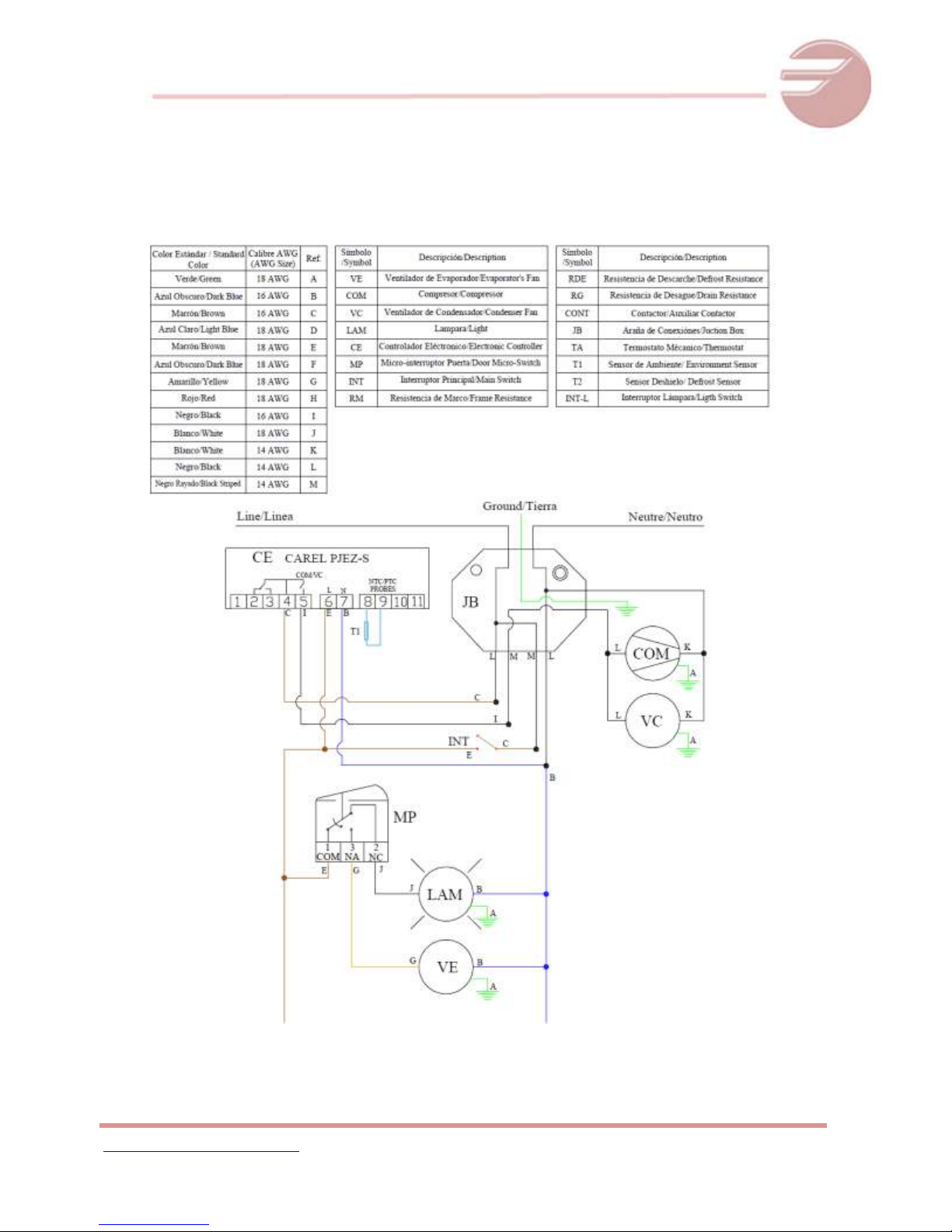
7 WIRING DIAGRAMS
QR 1 – QVR 1
PAGE 21
Page 22

www.Fagorcommercial.com
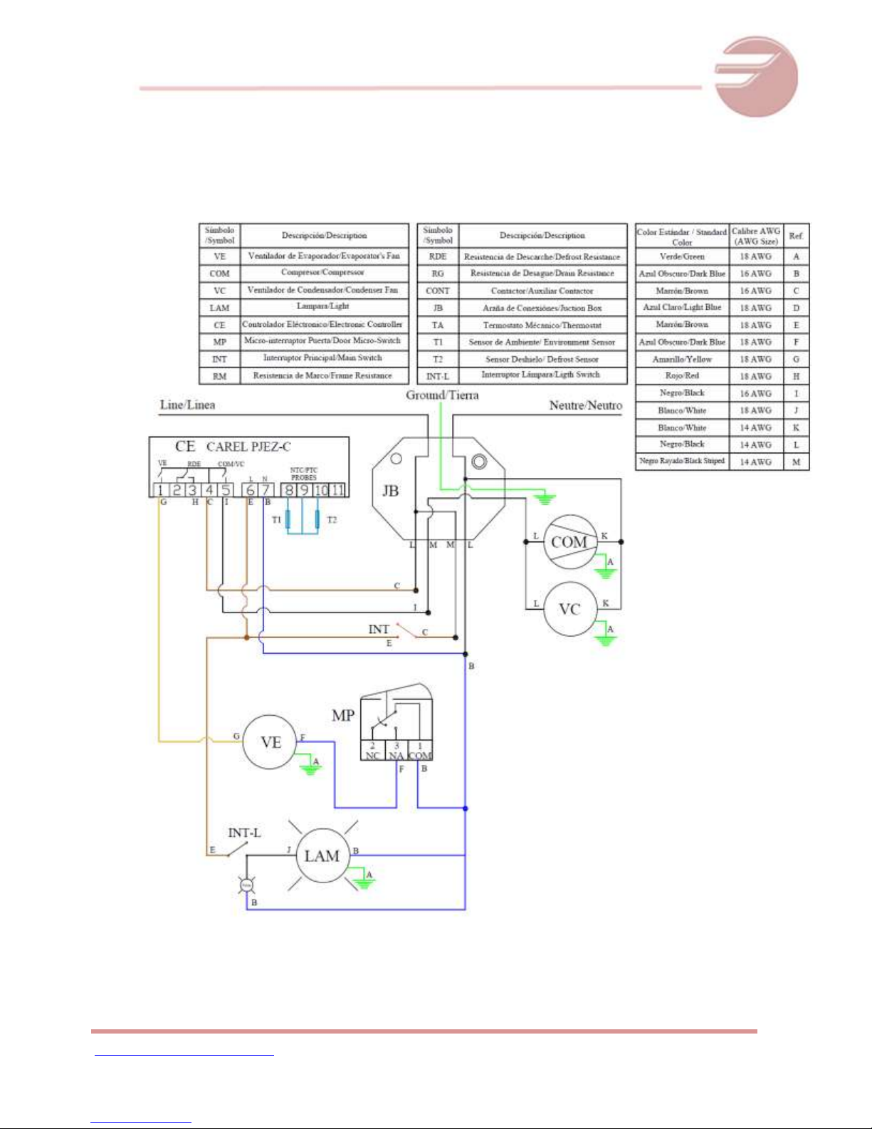
REACH-INS OPERATIONAL SERVICE MANUAL / Rev.JUN. 2015
QF1 – QVF 1
PAGE 22
Page 23

www.Fagorcommercial.com
REACH-INS OPERATIONAL SERVICE MANUAL / Rev.JUN. 2015
QR2 – QVR 2
PAGE 23
Page 24
www.Fagorcommercial.com
REACH-INS OPERATIONAL SERVICE MANUAL / Rev.JUN. 2015
QR 1G – QVR 1G
PAGE 24
Page 25

www.Fagorcommercial.com
REACH-INS OPERATIONAL SERVICE MANUAL / Rev.JUN. 2015
8 WARRANTY
AS OF APRIL 1, 2014
Three Years Parts & Labor Warranty: Fagor Commercial, Inc. (“Fagor”) Warrants to the fist-end-user
purchaser (the “User”) that the Fagor brand equipment sold hereunder, except for parts and accessories
which carry the warranty of a supplier (the “Equipment”) will be free from defects in material and factory
workmanship under normal conditions of use and maintenance and upon proper installation and start-up
in accordance with the User manual supplied with each Fagor unit. The obligation of this warranty is
covered by Fagor for a period of three (3) years from the date of installation (Warranty commencement
date), but in no event to exceed thirty-nine (39) months from the date of shipment from Fagor. Warranty is
Not Transferable.
Warranty Coverage: If there is a defect in material or factory workmanship covered by this Warranty
reported to Fagor during the period the applicable Warranty is in force and effect, Fagor will repair or
replace, at Fagor’s option, that part of the Equipment that has become defective and will cover
reasonable labor cost within the corresponding warranty period of time. Fagor shall bear all reasonable
labor costs in connection with the installation of these replacement parts, provided that, the installation is
conducted by Fagor or its authorized representative. Charges for warranty travel time round trip, total two
(2) hours or up to 100 miles total. Any charges exceeding those stated herein must have prior
authorization by Fagor. In case Fagor deems the equipment non-repairable, said equipment will be
replaced and the replacement unit(s) will carry the same warranty period from the original unit’s
installation date (original Warranty commencement date).
Additional Two Year Compressor Part Warranty: In addition to the warranty set above, Fagor warrants the
sealed compressor (part only) for an additional two (2) years based on the original installation date, but
not to exceed thirty-nine (39) months after shipment from the manufacturer. This warranty is for defects,
both in workmanship and material, under the normal and proper use and maintenance service. The two
(2) year extended warranty only applies to sealed parts of the compressor and does not apply to any
other part or component, including, but not limited to cabinet, temperature control, refrigerant, motor
starting equipment, fan assembly, or any other electrical or mechanical component.
Exclusions from and Conditions to Warranty Coverage: This Warranty does not cover parts or
accessories, which (a) carry the warranty of a supplier or (b) are abused. Application of this Warranty is
further conditioned upon the following:
Installation: The Equipment must be properly installed in accordance with Fagor’s installation
procedures and by a professional technician.
No Alteration: The Equipment must not have been modified or altered from its condition at the
date of original installation.
Use: FAGOR EQUIPMENT IS NOT DESIGNED FOR PERSONAL, FAMILY, OR HOUSEHOLD
PURPOSES, AND ITS SALE FOR SUCH PURPOSES IS NOT INTENDED. IN THE EVENT THE
EQUIPMENT IS SO USED, THIS WARRANTY SHALL BE NULL AND VOID, AND THE
EQUIPMENT IS SO USED, THIS WARRANTY SHALL BE NULL AND VOID, AND THE
EQUIPMENT SHALL BE DEEMED TO HAVE BEEN SOLD “AS IS-WHERE IS” WITHOUT ANY
WARRANTY OF ANY KIND, INCLUDING WITHOUT LIMITATION ANY WARRANTY OF TITLE,
NON-INFRINGEMENT, MERCHANT-ABILITY OR FITNESS FOR A PARTICULAR PURPOSE.
PAGE 25
Page 26

www.Fagorcommercial.com
REACH-INS OPERATIONAL SERVICE MANUAL / Rev.JUN. 2015
Proper Maintenance and Operation: The Equipment must be properly maintained and operated in
accordance with Fagor’s maintenance and operating procedures. All service, labor and parts
must be acquired from Fagor or its authorized service representative for the User’s area.
This warranty is void if failure is a direct result of handling and/or transportation, fire, water,
accident, misuse, acts of god(s), attempted repair by unauthorized persons, improper installation,
if serial number has been removed or altered, or if unit is used for purpose other than it was
originally intended.
Failure to comply with any of these conditions will void this Warranty. In addition, this Warranty does not
cover defects due to apparent abuse , misuse or accident.
Parts Warranty Coverage: Fagor warrants all new machine parts produced or authorized by Fagor to be
free from defects in material and workmanship for a period of 90 days from the Warranty Commencement
Date. If any defect in material and workmanship is found to exist within the warranty period, Fagor will
replace the defective part without charge. Defective parts become the property of Fagor.
Fagor will have no responsibility to honor claims received after the date the applicable Warranty expires.
Notwithstanding the foregoing , any claim with reference to the Equipment or any parts therefore for any
cause shall be deemed waived unless submitted by the User to Fagor within (30) days after the date the
User discovered, or should have discovered, the claim. In connection with all claims under this Warranty,
Fagor will have the right, at its own expense, to have its representatives inspect the Equipment at the
User’s premises and to request all of the User’s records pertaining to the Equipment to determine
whether a defect exists, whether the conditions set forth in this Warranty have been satisfied, and
whether or not the applicable Warranty is in effect.
THE FOREGOING WARRANTY IS IN LIEU OF AND EXCLUDES ALL OTHER WARRANTIES NOT
EXPRESSLY SET FORTH HEREIN, WHETHER EXPRESS OR IMPLIED BY OPERATION OF LAW OR
OTHERWISE, INCLUDING BUT NOT LIMITED TO ANY REPRESENTATION OF PERFORMANCE
AND ANY IMPLED WARRANTIES OF TITLE, NON-INFRINGEMENT, MERCHANTABILITY OR
FITNESS FOR A PARTICLULAR PURPOSE. NO OTHER WARRANTIES ARE AUTHORIZED ON
BEHALF OF FAGOR UNLESS SPECIFICALLY ISSUED BY FAGOR.
Fagor shall have no liability for incidental or consequential losses, damages including without limitation or
expenses, loss of sales, spoiled food, profits or goodwill, claims whether or not on account of refrigeration
failure or punitive or exemplary damages directly or indirectly arising from the sale, handling or use of the
Equipment or from any other cause relating thereto, whether arising in contract, tort, warranty, strict
liability or otherwise. Fagor’s liability hereunder in any case is expressly limited, at Fagor’s election, to
repair or replacement of Equipment or parts therefore or to the repayment of, or crediting the user with,
an amount equal to the purchase price of such goods.
PAGE 26
Page 27

www.Fagorcommercial.com
REACH-INS OPERATIONAL SERVICE MANUAL / Rev.JUN. 2015
Terms & Conditions
Prices & Specifications: Fagor reserves the right to change the prices and specifications of the equipment
and/or material without notice. Prices are FOB Fagor warehouses. All orders are subject to acceptance
by Fagor Commercial, Inc.
Terms: All orders are subject to credit approval. All Invoices not paid within the specified terms will be
subject to a 1.5% per month delinquency charge. Buyer agrees to pay all costs of collection including
such attorney’s fees as may be allowed by law.
Taxes: This price list does not include any Federal, State, City or Local taxes, which may apply and are
subject thereto.
Shipment: Requested carrier will be used upon request. Fagor has the right to ship via any responsible
carrier if requested carrier is unavailable. Shipping charges are payable by consignee and any claims
arising as such charges shall be resolved between the carrier and the consignee. Shipping dates are
approximates. Fagor is not responsible for any delays in deliveries that are beyond our control.
Damaged Merchandise: Inspect shipment for any damage, before accepting it. If damaged, open and
inspect the contents with the carrier. Any damage should be noted and reported on the delivering carrier’s
receipts. Fagor assumes nor responsibility for damages while in transit.
Concealed Damage: If there is concealed damage to the equipment, notify the carrier immediately.
Notification should be made verbally as well as in written form. Request an inspection by the shipping
company of the damaged equipment. Retain all crating material until inspection has been made.
Cancellations & Returns: Cancelled orders and returned merchandise are subject to a 25% restocking
and handling charge. Written authorization is required for a return of any equipment. All equipment
returned must be in its original factory crate; freight prepaid and must be in the same condition as
originally shipped by Fagor. Returns will only be authorized within 30 days of invoice date.
Warranty: Register your product with Fagor Commercial to validate you warranty. Service calls must be
made directly through Fagor service department. 1-(866)-463-2467 or e-mail:
us.service@onneragroup.com.
*You may register your product online at http//:www.fagorcommercial.com
PAGE 27
Page 28

www.Fagorcommercial.com
REACH-INS OPERATIONAL SERVICE MANUAL / Rev.JUN. 2015
Fagor Commercial, Inc.
13105NW 47thAve
Miami, Fl. 33054
Tel:(305) 7790170
Fax:(305)7790173 1-866-GO-FAGOR
www.fagorcommercial.com
PAGE 28
 Loading...