

Page 1
MARCH 2017
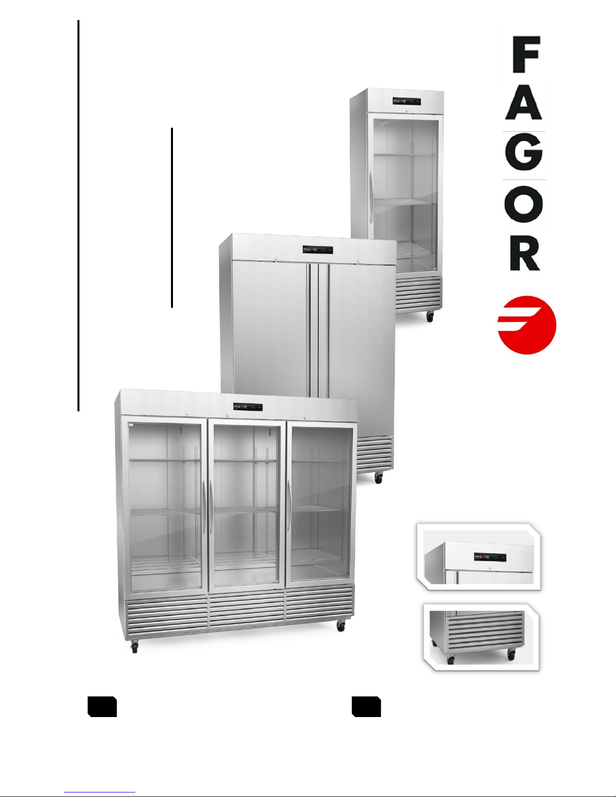
REFRIGERATORS AND FREEZERS
Manual Instructions
PREMIUM LINE “N”
Manual instructions
Installation and Operation
Manual de instrucciones
Uso y mantenimiento
ES
EN
DOCUMENT CODE: 602305M0063
Page 2

2
fagorindustrial.com
INDEX
ENGLISH
SPECIFICATION CHART ...........................................................................................................................4
MACHINE INTRODUCTION ..........................................................................................................................5
1.1 Introduction to machine & models .......................................................................................5
1.2 Important safety information ..................................................................................................5
INSTALLATION .................................................................................................................................................6
2.1 General information .....................................................................................................................6
2.2 Transport, handling, unpacking, location ......................................................................6
2.3 Intended use and restrictions ...............................................................................................7
2.4 Manufacturer’s identification label description .........................................................7
2.5 Installation and assembly ........................................................................................................8
2.6 Connections (electrical) ............................................................................................................8
OPERATION........................................................................................................................................................8
3.1 General information .....................................................................................................................8
3.2 Control panel description .......................................................................................................8
3.2.1 Electronic Control...............................................................................................................8
3.3 Machine settings and programs ............................................................................................9
MAINTENANCE .............................................................................................................................................. 10
4.1 General safety rules................................................................................................................ 10
4.2 Machine cleaning and maintenance routine ................................................................. 10
4.2.1 Cleaning the Condenser Coil ....................................................................................... 10
4.2.2 Cleaning the Gasket .......................................................................................................... 11
4.2.3 Draining the Unit ................................................................................................................ 11
4.3 Machine disposal ........................................................................................................................ 11
TROUBLESHOOTING CHART .................................................................................................................. 12
5.1 Troubleshooting chart ............................................................................................................ 12
Page 3

3
fagorindustrial.com
ESPAÑOL
INTRODUCCION ............................................................................................................................................ 13
1.1 Introducción a los equipos y modelos ........................................................................... 13
1.2 Información de seguridad ...................................................................................................... 13
INSTALACION ................................................................................................................................................ 14
2.1 Información General ................................................................................................................. 14
2.2 Transporte, manejo, desempaque y localización ...................................................... 14
2.3 Uso y restricciones ................................................................................................................... 15
2.4 Placa de identificación del Fabricante .......................................................................... 15
.......................................................................................................................................................................... 15
2.5 Instalación y Ensamble ........................................................................................................... 16
2.6 Conexiones ...................................................................................................................................... 16
OPERACION .................................................................................................................................................... 16
3.1 Información General ................................................................................................................. 16
3.2 Descripción del panel de control ..................................................................................... 16
3.2.1 Control electronico ......................................................................................................... 16
3.3 Configuraciones del Equipo ................................................................................................. 17
4.1 Reglas de seguridad general .............................................................................................. 18
4.2 Rutina de limpieza y mantenimiento del equipo ........................................................... 18
4.2.1 Limpiando el condensador ............................................................................................. 18
4.2.2 Limpieza del empaque plástico ..................................................................................... 19
4.2.3 Drenado ................................................................................................................................... 19
4.3 Disposición del equipo ............................................................................................................. 19
SOLUCIONANDO PROBLEMAS ............................................................................................................. 20
5.1 Solucionando problemas........................................................................................................ 20
ELECTRIC DIAGRAM / DIAGRAMA ELECTRICO .............................................................................. 21
ANEXOS ............................................................................................................................................................ 24
Page 4
4
fagorindustrial.com
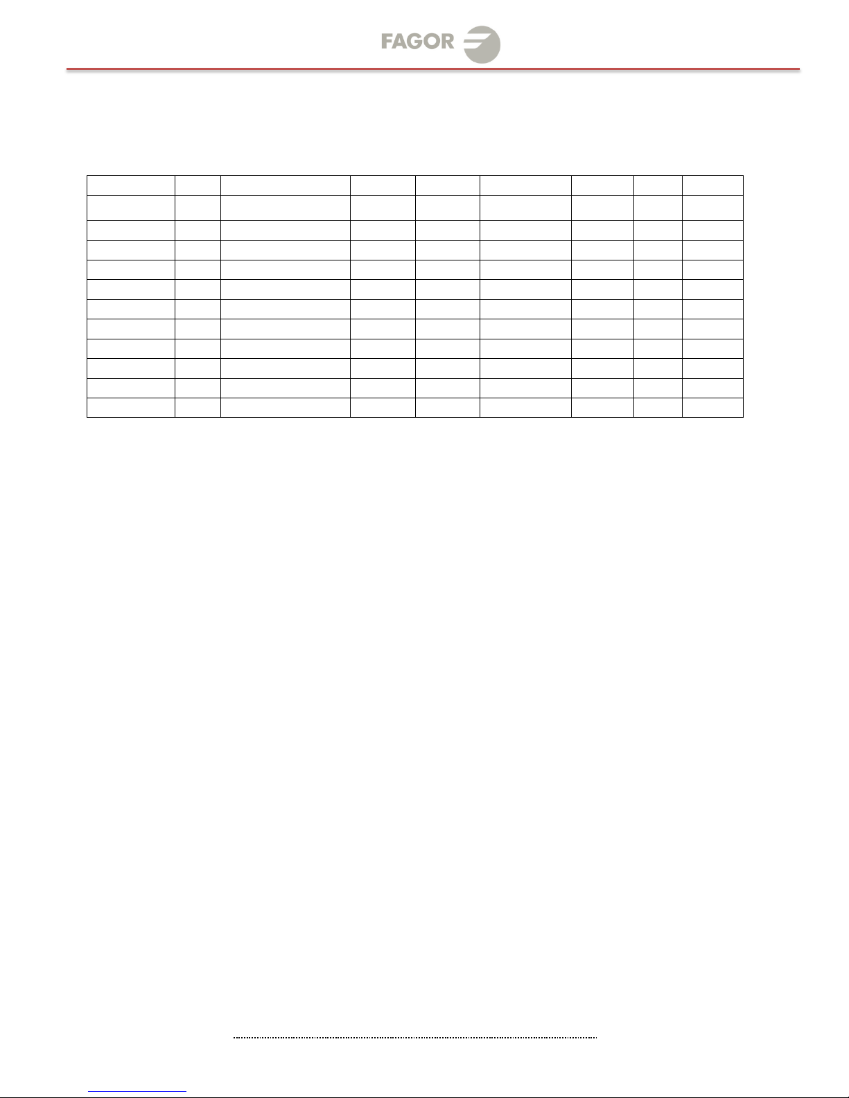
SPECIFICATION CHART
PREMIUM LINE “N”
NOTES:
__________________________________________________________________________________________
__________________________________________________________________________________________
__________________________________________________________________________________________
__________________________________________________________________________________________
__________________________________________________________________________________________
__________________________________________________________________________________________
__________________________________________________________________________________________
__________________________________________________________________________________________
_______________________________________________________________________________________
MODEL
HP
DIMENSIONS
(in) mm
VOLTAGE
(V)
AMP.
(A)
REFRIGERANT
CHARGE
TIPO
REFRIG.
BTUS/
HR
WEIGHT
(LB)
QVR-1 N
1/4
(17 x 31 x 80)
685 x 675 x 1825
115
220
5.0
3.1
11.3 Oz.
R-134a
1660
264 lb
QVR-1G N
1/3
(37 x 27 x 84)
1105 x 812 x 1981
115
220
6.6
3.5
11.3 Oz.
R-134a
2104
440 lb
QVR-2 N
1/3
(55 ¼ x 27 ¾ x 84 ½)
1371 x 812 x 1981
115
220
6.9
3.5
13.4 Oz.
R-134a
2104
476 lb
QVR-2G N
1/3
(17 x 31 x 80)
685 x 675 x 1825
115
220
5.2
3.9
13.4 Oz.
R-134a
1660
264 lb
QVR-3 N
1/2
(27 x 31 x 80)
685 x 812 x 1981
115
220
5.8
3.9
22.2 Oz
R-134a
1666
280lb
QVR-3G N
1/2
(37 x 27 x 84)
1105 x 812 x 1981
115
220
7.2
3.9
22.2 Oz
R-134a
2104
440 lb
QVF-1 N
3/4
(55 ¼ x 27 ¾ x 84 ½)
1371 x 812 x 1981
115
220
9.8
4.5
16.6 Oz.
R-134a
2104
476 lb
QVF-1G N
3/4
(17 x 31 x 80)
685 x 675 x 1825
115
220
9.8
4.5
16.6 Oz.
R-404A
2493
280 lb
QVF-2 N
3/4
(27 x 31 x 80)
685 x 812 x 1981
115
220
11.5
6.5
21.5 Oz.
R-404A
2493
280 lb
QVF-2G N
3/4
(55 ¼ x 27 ¾ x 84 ½)
1371 x 812 x 1981
115
220
11.5
6.5
21.5 Oz.
R-404A
3644
456 lb
QVF-3 N
1
(72 x 27 ¾ x84 ½ )
2060 x 812 x 1981
115
220
16.0
9.5
33.2 Oz.
R-404A
*
*
Page 5
5
fagorindustrial.com
MACHINE INTRODUCTION
1.1 Introduction to machine & models
FAGOR Reach Ins feature dual and triple paneL glass door, contributing to
energy efficiency and savings.
Standard digital control displays precise temperature for customer convenience
while
LED lights showcase the best out of your products.…
Details make this line unique .
New enhanced digital controller and display.
Digital controller refrigerators to keep food quality for longer period of
time.
Door alarm and user friendly controls to adapt to different enviroments.
Factory balanced refrigeration system, environmentally friendly R-134a /
R-404A.
• Stainless steel coved corner floor to meet NSF requirements.
• 4” castors and door locks standard.
• Recessed door handles.
1.2 Important safety information
DANGER: Power must be turned off and disconnected from the power
source whenever performing maintenance, repair or cleaning the
condensing unit.
If machine still running when power is off, disconnect power at the
circuit breaker before unplugging the machine.
WARNING: Machine and compressor warranties are void if failure is
due to improper electrical installation.
Do not introduce hot foods, chemical or corrosive products, drugs,
or open beverage bottles.
Notes
____________________________________________________________________________________________
____________________________________________________________________________________________
____________________________________________________________________________________________
____________________________________________________________________________________________
____________________________________________________________________________________________
____________________________________________________________________________________________
____________________________________________________________________________________________
____________________________________________________________________________________________
Page 6
6
fagorindustrial.com
INSTALLATION
2.1 General information
2.2 Transport, handling, unpacking, location.
2.3 Intended use and restrictions.
2.4 Manufacturer’s identification label description.
2.5 Installation and assembly.
2.6 Connections (electric, gas, water)
2.1 General information
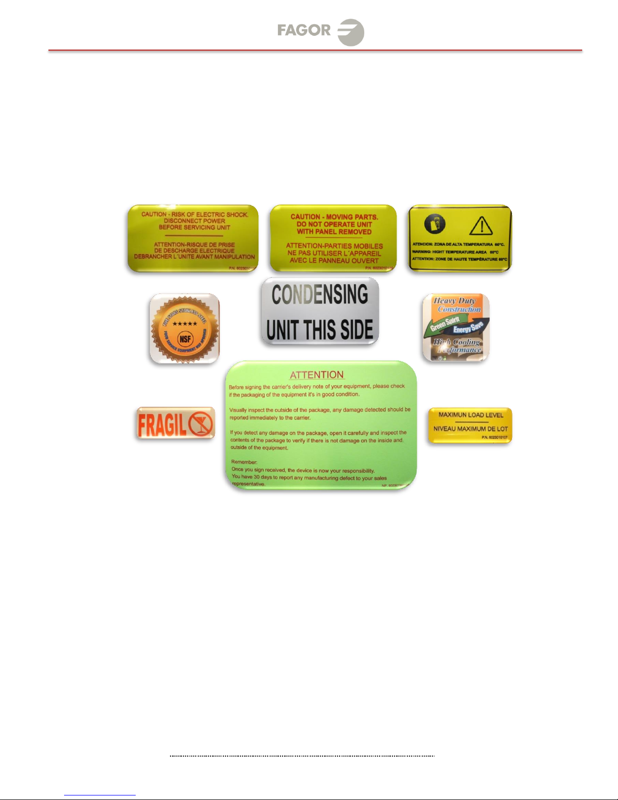
You can find in you equipment the following symbols, or stickers to identify some
type of warnings or useful information about your equipment.
2.2 Transport, handling, unpacking, location
Upon receiving your new FAGOR REACH IN, check the package and the machine for
any damages that may have occurred during transportation. Visually inspect the
exterior of the package, if damaged, open and inspect the contents with the
carrier. Any damage should be noted and reported on the delivering carrier’s
receipt.
In the event that the exterior is not damaged, yet upon opening, there is concealed
damage to the equipment notify the carrier immediately. Notification should be
made verbally as well as in written form. Request an inspection by the shipping
company of the damaged equipment.
Retain all crating material until inspection has been made. Contact the dealer
through which you purchased the unit.
Check the compressor compartment housing and visually inspect the refrigeration
package.
Be sure lines are secure and base is still intact.
Page 7

7
fagorindustrial.com
2.3 Intended use and restrictions
FAGOR equipment is not designed for personal, family, or household purposes,
and its sale for such purposes is not intended. In the event the equipment is so
used, this warranty shall be null and void, and the equipment is so used, this
warranty shall be null and void, and the equipment shall be deemed to have been
sold “as is-where is” without any warranty of any kind, including without limitation
any warranty of title, non-infringement, merchant-ability or fitness for a
particular purpose.
The equipments are conforms to UL and NSF- 7 standards.
If you want know more about other restrictions about your equipment see the
warranty that is located in the final part of your manual.
2.4 Manufacturer’s identification label description
The data plate is located inside the cabinet, near the top front, left corner.
Under no circumstances should the data plate be removed from the unit. The data
plate is essential to identify the particular features of your machine and it is of
great benefit to installers, operators, and maintenance personnel. It is
recommended that, in the event the data plate is removed, you copy down the
essential information in this manual for reference before installation. Removal of
data plate will void the warranty.
Model
Refrigerant
Type
Electricals
Serial Number
(8 digits and ends in “M”)
Code
Serial Number
Page 8
8
fagorindustrial.com
2.5 Installation and assembly
Units represented in this manual are intended for indoor use only. Be sure the
location chosen has a floor strong enough to support the total weight of the
unit and contents. For the most efficient operation, be sure to provide good air
circulation inside and outside of the unit.
INSIDE CABINET
The first cleaning must be made when you unpack the unit and before switching it
on. Clean it with water and a mild detergent. When it is clean and dry, insert the
accessories in the appropriate places, for the best use of the user.
OUTSIDE CABINET
Be sure the unit has good air circulation around it. Avoid hot corners and
locations near stoves and ovens. It is recommended the unit be installed no
closer than 2” from any wall. The place where the refrigerator is placed must be
open and clean, avoiding that de fan of the condensing unit absorbs materials
which are deposited then into the condenser blades and coil, which can produce
failures.
The unit should not be installed under ambient temperatures higher than 100 °F.
If the relative humidity is higher than 60 %, the door frames may sweat water. This
is not a malfunctioning of the unit.
2.6 Connections (electrical)
Refer to the amperage data in this manual or on data plate and your local code
or the National Electrical Code to be sure unit is connected to the proper power
source. Verify correct incoming voltage according to the Data Plate information.
The data plate in located inside the unit, near the top front left corner. Under
any circumstances should the data plate be removed from the unit.
The data plate is essential to identify the particular features of your unit and is
of great benefit to installers, operators and maintenance personnel. It is
recommended that, in the event the data plate is removed, you copy down the
essential information in this manual for reference before installation.
A protected circuit of the correct voltage and amperage must be run for
connection of the supply cord. Unit must be grounded and connected in
accordance with NEC Article 422 Appliances.
OPERATION
3.1 General information.
3.2 Control panel description.
3.3 Machine settings and programs.
3.1 General information
Good air flow inside the cabinet is critical. Do not block air flow to the fans.
Allow three inches of space along the front, back, and sides.
3.2 Control panel description
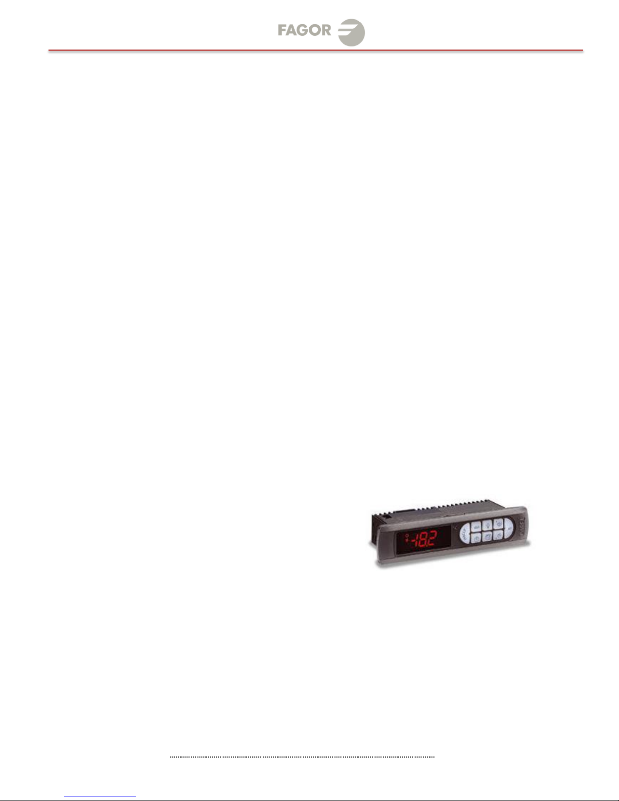
3.2.1 Electronic Control
After connecting your unit, turn ON rocker switch located next to the
controller. The display will light up showing the temperature inside the
unit. Also, the compressor and fan icons will flash for a period of three
minutes. After this delay the unit will start cooling.
Verify you don't have any alarms on the temperature controller. If after
you turn ON the equipment the controller shows the alarm icon or an error
code, call for technical service. They will help you fix the problem.
Page 9

9
fagorindustrial.com
3.3 Machine settings and programs
Changing the Set Point of the temperature on the controller
The unit comes with a factory default set point ( 32°F Refrigerators). These set
values will make the unit perform at its maximum capacity. Therefore, it is not
recommended to change the set point. If set point needs to be changed, follow the
next steps.
1. Push the SET button for one second. You should see a flashing number.
Release the button.
2. Press the up and down arrows to increase or decrease the set
temperature. Then press the set button to save the new set point.
Note:
The maximum value you can set in the controller is: For refrigerators: 5°C
(40°F)
3. If you wish decrease the value of the set point for a new temperature,
press the button DOWN arrow (see the picture below). Press this button
to reach the desired value. Release the button and then press the SET
button to keep, and save, the new value.
Note:
The minimum value you can set in the controller is: For refrigerators: -1°C
(30°F)
Manual Defrost
To select manual defrost, hold the button DOWN arrow for 5 seconds. The snow
flake icon will appear on the display. When this icon is solid it indicates that the
equipment is in Defrost mode.
To exit manual defrost, hold the DOWN button arrow for 5 seconds. The snow
flake icon will turn off. Wait 2 minutes for the compressor to start
FIGURE 1
ALARM MENU
ON/OFF
ENERGETIC SAFETY MODE
To increase Set Point of Temperature
/Continues cycle
To Change the set point
To access programming mode
To decrease Set Point of Temperature To set a manual defrost
Page 10

10
fagorindustrial.com
MAINTENANCE
4.1 General safety rules.
4.2 Machine cleaning and maintenance routine.
4.3 Machine disposal.
4.1 General safety rules
Neglecting the condenser coil cleaning procedures WILL VOID YOUR WARRANTY
associated with the compressor or cost to replace the compressor!
Proper cleaning of stainless steel requires soft cloths or plastic souring pads.
Never use steel pads, wire brushes or scrapers!
4.2 Machine cleaning and maintenance routine
Cleaning solutions need to be alkaline or non-chloride cleaners. Any cleaner
containing chlorides will damage the protective film of the stainless steel.
Chlorides are also commonly found in hard water, salts, and household and
industrial cleaners. If cleaner containing chlorides are used be sure to rinse
repeatedly and dry thoroughly upon completion.
Routine cleaning of stainless steel can be done with soap and water. Extreme
stains or grease should be cleaned with a non-abrasive cleaner and plastic scrub
pad. There are also stainless steel cleaners available which can restore and
preserve the finish of the steels protective layer.
Never use and acid based cleaning solution! Many food products have an acidic
content which can deteriorate the finish. Be sure to clean the ALL food products
from any stainless steel surface. Common items include peppers, tomatoes and
other vegetables.
4.2.1 Cleaning the Condenser Coil
Disconnect machine. Remove front bottom panel and carefully slide out the
condensing unit.
The condenser coil requires regular cleaning; recommended every 30-60
days, depending of the accumulation of dust and grease. If the buildup on
the coil consists of only light dust and debris the condenser coil can be
cleaned with a simple brush. Heavier dust build up may require a vacuum or
even compressed air to blow though the condenser coil. If heavy grease is
present there are de-greasing agents available for refrigeration use and
specifically for the condenser coils. The condenser coil may require a
spray with the de-greasing agent and then blown through with compressed
air.
Be sure all electrical and mechanical parts are dry before turning on the
power.
Never use a high pressure water wash for this cleaning procedure as water
can damage the electrical components located near or at the condenser
coil. Do not place filter material in front of condenser coil. This material
blocks air-flow to the coil similar to having a dirty coil!
If you keep the Condenser clean you will minimize your service expense and
lower your electrical costs. Failure to maintain a clean condenser coil can
initially cause high temperatures and excessive run times. Continuous
operation with dirty or clogged condenser coils can result in compressor
failures.
To put back the condensing unit in its place, slide in the unit carefully. BE
SURE DRAIN PIPE IS LOCATED OVER THE PAN. Replace front bottom panel
Page 11

11
fagorindustrial.com
4.2.2 Cleaning the Gasket
Gaskets require regular cleaning to prevent mold and mildew build up and
also to keep the elasticity of the gasket. Gasket cleaning can be done with
the use of warm soapy water. Avoid full strength cleaning products on
gaskets as this can cause them to become brittle and prevent proper seals.
Also, never use sharp tools or knives to scrape or clean the gasket which
could possibly tear the gasket and rip the bellows.
Gaskets can easily be replaced and do not require the use of tools or
authorized service persons.
The gaskets can be pulled out of the grove in the door and new gaskets can
be “pressed” back into place.
4.2.3 Draining the Unit
Each unit has a drain located inside the unit which removes the
condensation from the evaporator coil and evaporates it at an external
condensate evaporator pan. Each drain can become loose or disconnected
from moving or bumping the drain.
IF YOU NOTICE EXCESSIVE WATER ACCUMULATION ON THE INSIDE OF THE
UNIT be sure the drain tube is connected from the evaporator housing to
the condensate evaporator drain pan.
IF WATER IS COLLECTED UNDERNEATH THE UNIT you may want to check the
condensate evaporator drain tube to be sure it is still located inside the
drain pan. The leveling of the unit is important as the units are designed to
drain properly when on a level surface, if your floor is not level this can
also cause drain problems. Be sure all drain lines are free of
obstructions; typically food product is found blocking drain lines causing
water to back up and overflow the drain pans.
4.3 Machine disposal
The product’s life-cycle is around 7 to 10 year from the First use an instalation
date.
FAGOR equipment is manufactured without dangerous or toxic materials. Some
parts of the equipments are biodegradable.
The disposing after the product’s life-cycle shall be determined according to the
rules and laws established in the city or State of residence.
REMEMBER TO TAKE CARE OF THE ENVIRONMENT.
Page 12

12
fagorindustrial.com
TROUBLESHOOTING CHART
5.1 Troubleshooting guide chart
5.1 Troubleshooting chart
Follow the next steps before requesting warranty service. Failure to do
so, may result in service charges for you and may void your warranty:
1)
Refrigerator doesn’t work:
a. Check that the machine is still connected.
b. Check that the ON/OFF button is in the ON position.
2)
Refrigerator doesn’t reach temperature :
a. Verify unit is not on saving mode
b. Check that the thermostat or controller is not in OFF position.
c. Check that the machine is not in the defrost cycle.
d. Ensure Equipment is in a ventilated place and removed
minimum of 2 inches from any other appliance and away
from any heat source.
e. The environment maximum temperature must be 38 °C/ 100°F.
f. To insure proper air flow, product must not be placed
higher than the maximum level mark located on the internal
wall of the unit.
g. If FREEZER, check that the temperature is not Celsius.
h. Check that the gasket is in good condition and door is sealed.
i. Check that the fan is moving. Open the door and press and
hold doors witch for verification.
j. Don’t put any food inside until the unit has reached the proper
temperature.
k. If FREEZER, food must be previously frozen before being placed
inside the cabinet.
l. Be sure castors or legs were installed.
3)
There is water inside the refrigerator:
a. Check that the drain pan inside the cabinet is in position.
b. Check that there is not food clogging the drain line.
4)
There is water under the refrigerator:
a. Check that the drain pipe is over the pan.
b. Check that the cabinet is level.
Warning: To i n s u r e proper operation of equipment, it is recommended
that the unit is on for 24 hours prior to the introduction of
perishables.
Page 13

13
fagorindustrial.com
INTRODUCCION
1.1 Introducción a los equipos y modelos
Los armarios FAGOR cuentan con puerta de vidrio de panel doble y triple,
contribuyendo al ahorro y eficiencia energética.
Estándar de control digital muestra la temperatura precisa para
comodidad del cliente mientras
Luces LED exhibir lo mejor de sus productos...
Los detalles hacen que esta línea única.
• Nuevo mejorada pantalla y controlador digital.
• Refrigeradores controlador digital para mantener la calidad de
los alimentos durante largo periodo de tiempo.
• Puerta alarma y usuario amigables controles para adaptarse a
diversos ambientes.
• Fábrica había equilibrado sistema de refrigeración ecológico R134A.
• Acero inoxidable coved piso esquina para cumplir los
requerimientos de NSF.
• 4 "ruedas y cerraduras de puerta estándar.
Manijas de puerta empotrado.
1.2 Información de seguridad
El equipo debe ser apagado y desconectado de la fuente de
alimentación cuando realizar el mantenimiento, reparación o limpieza
de la unidad condensadora.
Si la máquina sigue funcionando cuando está apagado, desconecte la
alimentación principal antes de desenchufar la máquina.
La garantía de la maquina y el compresor se anulan debido a la
instalación eléctrica inadecuada.
No introdusca alimentos calientes, productos quimios o corrosivos,
drogas o botellas destapadas
Notes
____________________________________________________________________________________________
____________________________________________________________________________________________
____________________________________________________________________________________________
____________________________________________________________________________________________
____________________________________________________________________________________________
____________________________________________________________________________________________
____________________________________________________________________________________________
____________________________________________________________________________________________
ESPAÑOL
Page 14

14
fagorindustrial.com
INSTALACION
2.1 Información General
2.2 Transporte, manejo, desempaque y localización
2.3 Uso y restricciones
2.4 Placa de identificación del Fabricante
2.5 Instalación y ensamble
2.6 Conexiones (eléctricas, agua, gas)
2.1 Información General
En el equipo usted ecnontrara los siguientes simbolos y/o pegatinas que le
ayudaran a identificar peligros y/o informacion util relacionada con su equipo.
2.2 Transporte, manejo, desempaque y localización
Al momento de recibir su equipo FAGOR, verifique el empaque en búsqueda de
daños que pudieran haber ocurrido durante el transporte del mismo. Inspeccione
de manera visual el exterior del empaque, si el mismo se encuentra dañado, abra e
inspeccione, delante de la empresa transportadora, todo el equipo. Cualquier
daño debe ser anotado y reportado en el recibo de entrega de la empresa
transportadora.
IMPORTANTE: Una vez que se haya retirado todo el material del empaque, revise
por la parte posterior del equipo el compartimiento del compresor. Inspeccione
visualmente el sistema de refrigeración y asegúrese que las tuberías no estén
dobladas y que no presenten alguna fisura, asegúrese que la base esté intacta.
Si al momento de abrir el empaque existe un daño oculto en el equipo, notifíquelo
de inmediato a la empresa transportadora mediante un llamado telefónico así
como también de manera escrita. Solicite una inspección por parte de la compañía
transportadora si el equipo está dañado. Conserve todo el material de embalaje
hasta que se haya realizado la inspección, contacte al proveedor con el que
adquirió su equipo FAGOR.
Page 15

15
fagorindustrial.com
2.3 Uso y restricciones
EL equipo FAGOR no está diseñado para fines personales, familiares o del hogar,
y su venta para esos fines no está prevista. En el caso de que el equipo se utiliza
con tal fin, esta garantía será nula de pleno derecho, y el equipo se considerará
que se han vendido "como es, donde es" sin garantía de ningún tipo, incluyendo, sin
limitación, cualquier garantía de título, no infracción, los comerciantes la
capacidad o aptitud para un propósito en particular.
Los equipos cumplen con los estándares de las normas UL y NSF-7
Si usted quiere saber más acerca de otras restricciones relacionadas con el
equipo ver la garantía que se encuentra localizada al final del manual.
2.4 Placa de identificación del Fabricante
La placa de datos se encuentra dentro del gabinete, cerca de la parte superior
delantera, a la izquierda. Bajo ninguna circunstancia debe quitar la placa de
datos de la unidad. La placa de datos es esencial para identificar las
características particulares de su máquina y es de gran beneficio para los
instaladores, operadores y personal de mantenimiento. Se recomienda que, en
caso de que se retira la placa de datos, copie la información esencial en este
manual para referencia antes de la instalación.
Remoción de la placa de datos anulará la garantía.
Modelo
Tipo
Refrigerante
Especificaciones
eléctricas
Numero de Serie
(8 dígitos con terminación
en “M”)
Código
Numero de Serie
Page 16

16
fagorindustrial.com
2.5 Instalación y Ensamble
Las unidades presentadas en este manual están diseñadas para uso interior
solamente. Asegúrese de que la ubicación elegida tiene un piso lo suficientemente
fuerte para soportar el peso total de la unidad y contenidos. Para la operación
más eficiente, asegúrese de proveer buena circulación de aire dentro y fuera de la
unidad.
DENTRO DEL GABINETE
La primera limpieza debe hacerse cuando Desempaque el aparato y antes de
encenderlo. Limpie con agua y un detergente suave. Cuando esté limpio y seco,
inserte los accesorios en los lugares apropiados, para el mejor aprovechamiento
del usuario.
FUERA DEL GABINETE
Asegúrese que la unidad tenga buena circulación de aire alrededor de él. Evite
rincones calientes y lugares cerca de estufas y hornos. Se recomienda instalar la
unidad a no menos de 2 " de cualquier pared. El lugar donde se coloca el
refrigerador debe estar ventilado y limpio, evitando que el ventilador de la
unidad condensadora absorba materiales que luego se depositan en las láminas
del condensador y bobina, que puede producir fallas.
La unidad no debe ser instalada bajo temperaturas ambientales superiores a 100 °
F.Si la humedad relativa es superior al 60%, los marcos de las puertas pueden
sudar agua. Esto no es un mal funcionamiento de la unidad.
2.6 Conexiones
Tome en cuenta los datos sobre el amperaje y voltaje que aparecen en la placa
matricula del equipo. Es indispensable que la instalación eléctrica del usuario
cumpla con los requerimientos y normatividades eléctricas nacionales y locales
correspondientes al lugar donde se instalara el aparato.
El equipo debe ser instalado en un circuito protegido por sobrecargas y/o cortos
circuitos así como por variaciones de voltaje.
IMPORTANTE: El contacto o enchufe debe tener conductor de tierra física
obligatoriamente.
OPERACION
3.1 Información General
3.2 Descripción del panel de control.
3.3 Configuraciones del Equipo.
3.1 Información General
La buena circulación de aire dentro del gabinete es crítico. No obstruya el
flujo de aire de los ventiladores. Coloque el equipo a no menos de 3
pulgadas de espacio a lo largo del frente, parte posterior y los lados
como separacion para una ventilacion adecuada.
3.2 Descripción del panel de control
3.2.1 Control electronico
Después de conectar su unidad, active el interruptor situado en el
controlador. La pantalla se encenderá mostrando la temperatura dentro
de la unidad. Además, los iconos del compresor y del ventilador
destellarán durante un período de tres minutos. Después de este retraso,
la unidad comenzará de enfriamiento.
Verificar que no tienes ninguna alarma en el regulador de temperatura. Si
después de encienda el equipo el controlador muestra el icono de alarma o
un código de error, solicite servicio técnico. Te ayudarán a solucionar el
problema.
Page 17

17
fagorindustrial.com
3.3 Configuraciones del Equipo
Cambiando el Set Point (ajuste de temperatura)
El controlador tiene un SET POINT de temperatura programado de fábrica
para garantizar el correcto funcionamiento del equipo. Si usted lo desea,
puede cambiar el SET POINT de temperatura. Para ello, siga los pasos:
1. Pulse el botón de SET durante 2 segundos. Usted verá un número
parpadeando, suelte el botón, el número parpadeando es el valor del
SET POINT de temperatura.
2. Si deseas aumentar el valor del SET POINT para una nueva temperatura,
presione el botón de flecha hacia arriba. Pulse este botón para
alcanzar el valor deseado, suelte el botón y luego presione el botón de
SET para guardar el nuevo valor.
Nota:
El valor maximo que el control puede mostrar es en refrigeradores: 5°C
(40°F)
3. Si desea disminuir el valor del SET POINT para una nueva temperatura,
presione el botón de flecha hacia abajo. Pulse este botón para alcanzar
el valor deseado, suelte el botón y luego presione el botón de SET para
guardar el nuevo valor.
Nota:
El valor minimo que el control puede mostrar es en refrigeradores: 1°C (30°F)
Deshielo Manual
Para selecionar el deshielo manual, mantener precionado el boton de flecha
hacia abajo abajo por 5 segundos. El icono del deshielo parpadeara y se
mostrara en la pantalla. Cuando el icono deje de parpadear el equipo estara en
modo de deshielo.
FIGURA 1
Menú alarmas
Encendido/Apagado
Modo Ahorro energía
Incrementa el Set Point de la Temperatura
Ciclo Continuo
Cambiar el set point
Acceder al modo de
configuración
Decrementar el Set Point de la Temperatura
Page 18

18
fagorindustrial.com
Para salir del modo deshielo mantener presionado por 5 segundos el boton de
la flecha hacia abajo.el icono de dehsielo se apagara. Esperar 2 minutos para que
el compresor comience a funcionar.
MANTENIMIENTO
4.1 Reglas de seguridad general.
4.2 Rutina de limpieza y mantenimiento del equipo
4.3 Disposición del equipo
4.1 Reglas de seguridad general
Cualquier negligencia con los procedimientos de limpieza del compresor puede
anular la garantía y generar un costo del remplazo del compresor.
Para la limpieza del acero inoxidable use paños suaves o esponjas. Nunca usar
esponjas metalicas, cepillos de alambre o algun tipo de lija.
4.2 Rutina de limpieza y mantenimiento del equipo
La limpieza debe ser a base de limpiadores alcalinos o libres de cloro. Cualquier
limpiador que contiene cloruros dañará la película protectora del acero
inoxidable. Cloruros son también comúnmente encontrados en agua dura, sales y
productos de limpieza domésticos e industriales. Si se utilizan limpiador que
contienen cloruros asegúrese de enjuagar varias veces la superficie y seque bien
al finalizar. La limpieza de rutina del acero inoxidable puede hacerse con agua y
jabón. Las manchas de extremo o grasa deben limpiarse con un paño no abrasivo
exfoliante limpiador. También hay limpiadores de acero inoxidable disponibles que
se pueden restaurar y conservar el acabado de la capa protectora de los aceros.
Nunca use una solución de limpieza a base de ácido. Muchos productos
alimenticios tienen un contenido ácido que puede deteriorar el acabado. Asegúrese
de limpiar los todos los productos alimenticios de cualquier superficie de acero
inoxidable.
4.2.1 Limpiando el condensador
Desconecte la máquina. Quite el panel delantero inferior y cuidadosamente
Deslice hacia afuera la unidad condensadora.
La bobina del condensador requiere una limpieza regular; recomendado
cada 30 a 60 días, dependiendo de la acumulación de polvo y grasa. Si la
acumulación en la bobina consta de sólo luz el polvo y suciedad del
serpentín del condensador puede limpiarse con un cepillo simple. Mayor
acumulación de polvo puede requerir un vacío o incluso aire comprimido
para soplar aunque el serpentín del condensador. Si hay grasa pesada hay
agentes desengrasante disponible para el uso de refrigeración y
específicamente para los serpentines del condensador. La bobina del
condensador puede requerir un spray con el agente desengrasante y luego
soplado a través con aire comprimido.
Asegúrese de que todas las partes mecánicas y eléctricas estén secas antes
de conectar la alimentación.
Nunca usar agua de alta presión para este procedimiento de limpieza, puede
dañar los componentes eléctricos se encuentran cerca o en el serpentín
del condensador. No coloque el material del filtro delante de la bobina
del condensador. Este material bloquea el flujo de aire a la bobina similar
a tener una bobina sucia!
Si mantienes el condensador limpio va a reducir al mínimo sus gastos de
servicio y reducir sus costos de electricidad. No mantener un serpentín del
condensador limpio inicialmente puede causar altas temperaturas y
excesivos ciclos de operación. Operación continua con serpentines del
condensador sucio u obstruido puede ocasionar fallas del compresor.
Para devolver la unidad condensadora en su lugar, deslice la unidad con
cuidado. ASEGÚRESE DE QUE EL TUBO DE DESAGÜE ESTÁ SITUADO SOBRE
LA BANDEJA.
Page 19

19
fagorindustrial.com
4.2.2 Limpieza del empaque plástico
El empaque requiere una limpieza regular para evitar la acumulación de
moho arriba y también para mantener la elasticidad del mismo. La limpieza
puede realizarse con el uso de agua caliente y jabón. Evitar productos de
limpieza ya que esto puede causar que se tornen quebradizos y evitar el
sellado adecuado. Además, nunca utilice herramientas o cuchillos para
raspar o limpiar el empaque, posiblemente podrían romper el empaque y
rasgar el fuelle.
Los empaques pueden ser reemplazados fácilmente y no requieren el uso de
herramientas o personas autorizadas de servicio.
4.2.3 Drenado
Cada unidad tiene un drenado ubicado dentro de la unidad que elimina la
condensación de la bobina del evaporador y lo evapora en un exterior
condensado del evaporador. Cada drenaje puede ser removido o
desconectado.
Si percibe excesiva acumulación de agua en el interior de la unidad
asegúrese de que está conectado el tubo de desagüe del evaporador a la
bandeja de drenaje de condensado del evaporador.
La nivelación de la unidad es importante, ya que las unidades están
diseñadas para drenar adecuadamente cuando sobre una superficie
nivelada, si el piso no está nivelado esto también puede causar problemas
de drenaje. Asegúrese de que todas las líneas de desagüe estén libres de
obstrucciones.
4.3 Disposición del equipo
El ciclo de vida promedio de los productos FAGOR es de 7 a 10 años apartir de
la fecha de uso e intalacion primera.
Los equipos FAGOR son fabricados sin materiales toxicos o peligorosos. Algunas
partes son biodegradables.
La disposicion final del equipo despues del termino del ciclo de vida sera definido
por el cliente de acuedo a las reglas, y leyes establecidas en la ciudad y/o estado
de residencia.
RECUERDE CUIDAR EL MEDIO AMBIENTE.
Page 20

20
fagorindustrial.com
SOLUCIONANDO PROBLEMAS
5.1 SOLUCIONANDO PROBLEMAS
5.1 Solucionando problemas
Algunas veces, las fallas son debido a causas simples que pueden ser
solucionadas por el usuario. Antes de pedir ayuda a un técnico calificado,
debe hacer algunas verificaciones. Estas fallas no están cubiertas por la
garantía:
1) El refrigerador no funciona:
a. Verifique que la maquina este conectada de forma correcta y que
exista el voltaje correcto para el equipo.
b. Verifique que el “Botón Encendido/Apagado” este en la posición de
“Encendido”.
2) El refrigerador no da la temperatura adecuada:
a. Verifique que el equipo no está en el ciclo de deshielo.
b. Verifique que la temperatura no esté en °F.
c. Verifique que el control no marque alguna alarma.
d. Verifique que el SET POIT de temperatura es el correcto.
e. Verifique que no existe obstrucción al flujo del aire en el interior
del equipo.
f. Verifique que el ventilador ó los ventiladores funcionan
correctamente. Abra la puerta y presione el interruptor (microswitch) de la puerta para verificarlo.
g. Verifique que no haya hielo en el evaporador.
h. Asegúrese que el condensador este limpio y que no haya objetos
que obstruyan el paso de aire por las tuberías del condensador.
i. Verifique que el ventilador del condensador funciona.
3) Hay agua dentro del equipo:
a. Asegúrese que el panel de drenaje que se encuentra en el interior
del gabinete esté en su posición correcta.
b. Verifique que no haya alimento obstruyendo la línea del drenaje.
4) Hay agua debajo del equipo:
a. Verifique que el tubo de drenaje esté dentro de la bandeja de
evaporación.
b. Verifique que el gabinete este nivelado.
Page 21

21
fagorindustrial.com
ELECTRIC DIAGRAM / DIAGRAMA ELECTRICO
QVR-1_N
QVR-2_N
Page 22

22
fagorindustrial.com
QVR-3_N
QVF-1_N
Page 23

23
fagorindustrial.com
QVF-2_N
QVF-3_N
Page 24

24
fagorindustrial.com
ANEXOS
Page 25

25
fagorindustrial.com
Page 26

Circuito Exportación N° 201
Parque Industrial Tres Naciones
San Luís Potosí, S.L.P. México
Teléfono Planta S.L.P.: + 52 (444) 137 0500 Ext.538
Sin costo: 01 800 00 FAGOR
MULTI-SOLUTION MANUFACTURER OF FOODSERVICE EQUIPMENT
13105 NW 47th Ave
Miami, Fl. 33054
Phone: (866) 463-2467
 Loading...