

Page 1

Hand pump
PUMP1000-4L-CONTROL
User manual
Page 2

2
BA 20
Schaeffler Group Industrial
Safety guidelines and symbols
High product safety
Our products correspond to the current level of research and
technology. If the bearing arrangement is designed correctly,
the products are handled and fitted correctly and as agreed and
if they are maintained as instructed, they do not give rise to any
direct hazards.
Follow instructions
This publication describes standard products.
Since these are used in numerous applications, we cannot make
a judgement as to whether any malfunctions will cause harm to
persons or property.
It is always and fundamentally the responsibility of the designer
and user to ensure that all specifications are observed and that all
necessary safety information is communicated to the end user.
This applies in particular to applications in which product failure and
malfunction may constitute a hazard to human beings.
Definition of guidelines
and symbols
The warning and hazard symbols are defined along the lines of
ANSI Z535.6–2006.
The meaning of the guidelines and symbols is as follows:
Warning
If these safety guidelines are not observed, death or serious injury
may occur.
If these safety guidelines are not observed, damage or
malfunctions in the product or the adjacent construction will occur.
Note
There follows additional or more detailed information that must be
observed.
Numbers within a circle are item numbers.
Page 3

Schaeffler Group Industrial BA 20 3
Page
Features Scope of delivery ....................................................................... 5
Design and
safety guidelines
Intended purpose ...................................................................... 6
Qualified personnel................................................................... 6
Protective equipment ................................................................ 6
Hydraulic oil .............................................................................. 7
Maximum pressure.................................................................... 7
Ambient conditions ................................................................... 7
Initial operation Checking the hand pump........................................................... 8
Setting the stroke volume.......................................................... 9
Spacer ring .......................................................................... 9
Mounting the spacer ring ..................................................... 9
Dismounting the spacer ring ................................................ 9
Operation Mounting the rolling bearing...................................................... 10
Mounting the hydraulic nut........................................................ 10
Connecting the hand pump ....................................................... 11
Venting the hand pump ....................................................... 11
Connection .......................................................................... 11
Venting the hydraulic nut........................................................... 11
Setting the start position ........................................................... 12
Determining the start pressure............................................. 12
Building up the start pressure.............................................. 12
Setting the end position ............................................................ 13
Determining the number of strokes ...................................... 13
Moving the rolling bearing to the end position ..................... 14
Dismounting the hand pump ..................................................... 14
Releasing the pressure ........................................................ 14
Removing the hand pump .................................................... 14
Maintenance ............................................................................. 15
Changing the oil................................................................... 15
Cleaning the tank................................................................. 15
Hand pump
Page 4

4 BA 20 Schaeffler Group Industrial
Page
Techni ca l data Ordering designation................................................................. 16
EU Declaration of Conformity..................................................... 17
Digital manometer Features .................................................................................... 18
Operation.................................................................................. 18
Control keys ........................................................................ 18
Control diagram................................................................... 19
Maintenance ............................................................................. 20
Changing the battery ........................................................... 20
Dismantling......................................................................... 20
Mounting............................................................................. 20
Technical data........................................................................... 21
Ordering designations............................................................... 21
Troubleshooting ................................................................................................. 22
Value table Displacement distance, number of strokes................................ 24
Hand pump
Page 5
Schaeffler Group Industrial BA 20 5
Features The hand pump and accessories are supplied in a sturdy metal case
made from sheet steel. The metal case and parts should be checked
immediately for any damage during transit. The carrier should be
informed of any damage without delay.
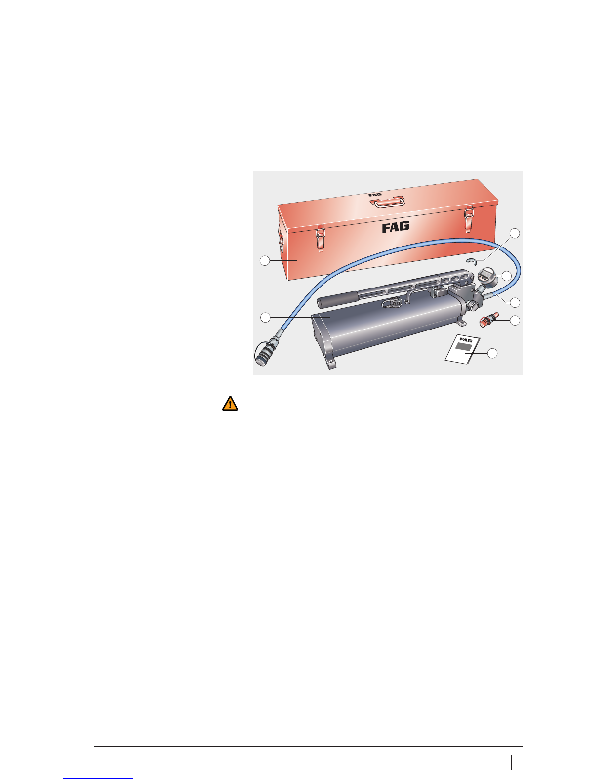
Scope of delivery The items included in delivery are shown in Figure 1.
Warning
If the hand pump or accessories are damaged, they must not be
used. Do not attempt to carry out repairs. Any repair work required
should be carried out by Schaeffler KG, Schweinfurt.
Metal case
Hand pump
Spacer ring (half ring),
HYDNUT50 to 150
Digital manometer
High pressure hose
with coupling sleeve
Coupling nipple
User manual
Figure 1
Scope of delivery
1
2
3
5
4
7
6
00015F98
Hand pump
Page 6
6 BA 20 Schaeffler Group Industrial
Hand pump
Design and
safety guidelines
Intended purpose
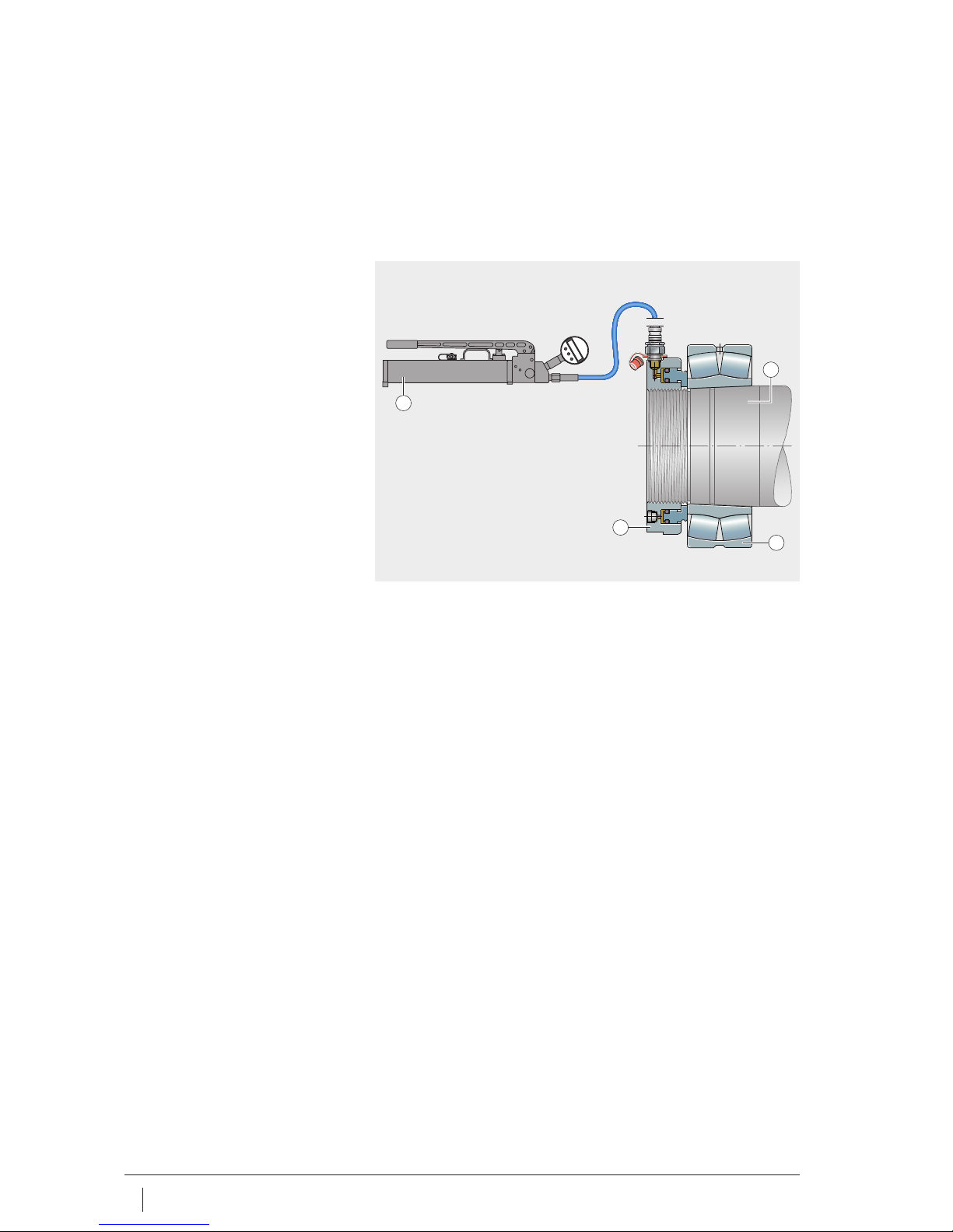
The hand pump PUMP1000-4L-CONTROL is used to operate
FAG hydraulic nuts. These are used to mount rolling bearings on
a tapered seat, Figure 2.
Note
The hand pump can also be used for dismounting,
see BA 007, FAG Hand Pump Sets.
Qualified personnel The hand pump must only be used by qualified personnel.
A person defined as qualified personnel:
■ is authorised to use the hand pump
■ has all the necessary knowledge
■ is familiar with the safety guidelines
■ has read and understood this manual.
Protective equipment Protective equipment is intended to protect personnel against
health hazards.
When working with the hand pump, the following protective
equipment must be used at all times:
■ protective goggles
■ gloves or oil-based cream.
Tapered seat
Rolling bearing
Hydraulic nut
Hand pump
Figure 2
Mounting
3
2
1
4
00015F99
Page 7

Schaeffler Group Industrial BA 20 7
Hydraulic oil The only hydraulic oils that can be used are:
■ any hydraulic oils with a viscosity of 32 mm
2
/s at +40 °C.
Only clean hydraulic oil should be used.
If the oil is not clean, this may lead to blockage of the filter fitted.
Warning
Hydraulic oil can cause irritation to skin and respiratory passages.
Skin contact should therefore be avoided, vapours and fumes
should not be inhaled. Eyes must be protected against hydraulic oil.
Maximum pressure The hand pump delivers a pressure of up to 1000 bar. The maximum
pressure that can be used with a hydraulic nut is 800 bar.
Warning
800 bar must never be exceeded.
The manometer must be monitored continuously during operation.
Ambient conditions The hand pump should be used under the following ambient
conditions:
■ The surface underneath must be even and capable
of supporting loads
■ Temperature: 0 °C to +60 °C
■ Humidity: max. 90%, no condensation.
Ensure that the ambient conditions are maintained throughout
the operating period.
Page 8
8 BA 20 Schaeffler Group Industrial
Hand pump
Initial operation This manual describes the initial operation of the hand pump,
for information on the initial operation of hydraulic nuts
see BA 004, FAG Hydraulic Nuts.
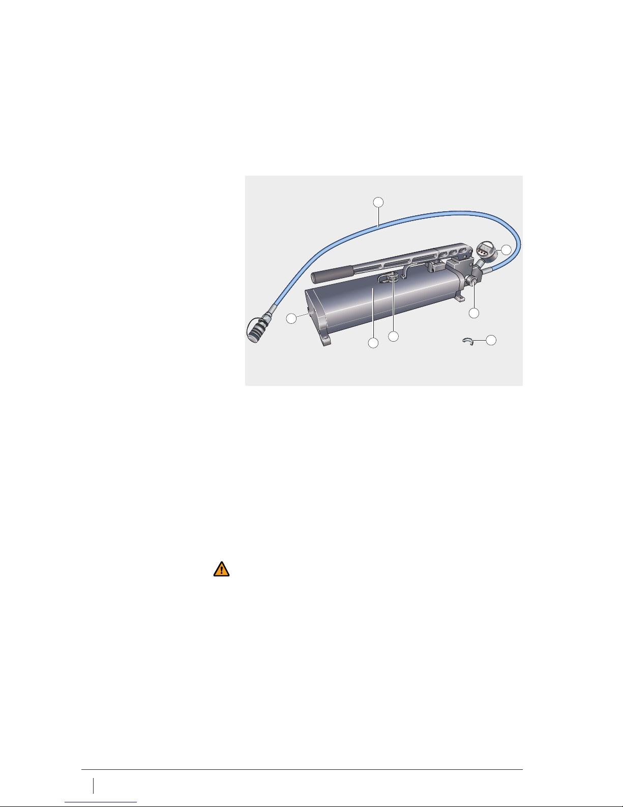
Checking the hand pump Before any use, check the hand pump and the accessories to be
used, Figure 3.
The hand pump can only be put into operation if all the following
questions can be answered with “yes”:
■ Is the hand pump free from corrosion, cracks and damage?
■ Is the tank completely filled with a suitable hydraulic oil,
see page 7?
■ Is the escape valve
easy to move and free from damage?
■ Is the battery in digital manometer in acceptable condition
(if not, see the section Changing the battery, page 20)?
■ Is the high pressure hose free from damage and kinks?
■ Is the high pressure hose suitable for at least 1000 bar?
■ Is the required stroke volume set
(see the section Setting the stroke volume, page 9)?
Warning
If the hand pump or accessories are damaged, they must not be
used. Do not attempt to carry out repairs. Any repair work required
should be carried out by Schaeffler KG, Schweinfurt.
Hand pump
Tank
Tank lid
Escape valve
Spacer ring (half ring),
HYDNUT50 to 150
Digital manometer
High pressure hose
Figure 3
Checking for initial operation
2
1
3
4
5
7
6
00015F97
Page 9
Schaeffler Group Industrial BA 20 9
Setting the stroke volume The stroke volume of the hand pump can be adjusted as a function
of the hydraulic nut used.
Spacer ring The spacer ring (half ring) restricts the stroke and thus reduces
the stroke volume. The volume without a spacer ring (half ring)
is 0,9
cm
3
per stroke, when the spacer ring (half ring) is mounted,
0,2
cm
3
of hydraulic oil is pressed into the hydraulic nut on
a complete stroke.
The spacer ring (half ring) should be mounted when using:
■ HYDNUT50 to HYDNUT150.
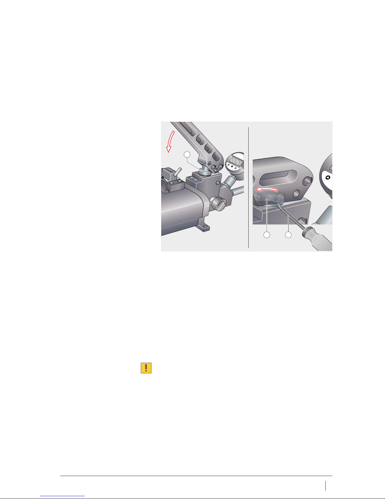
Mounting the spacer ring A small flat blade screwdriver is recommended as a mounting tool,
Figure 4:
■ Insert the spacer ring (half ring) (position A, )
■ Press the arm of the hand pump down almost to the stop
■ Rotate the spacer ring (half ring) by 180° into position B, .
Dismounting the spacer ring ■ Press the arm down almost to the stop
■ Rotate the spacer ring (half ring) by 180° into position A,
■ Move the arm upwards
■ Remove the spacer ring (half ring).
Do not replace the spacer ring (half ring) during operation of
the pump. Any inaccuracies in the displacement distance can
damage the bearing.
Spacer ring (half ring),
position A
Spacer ring (half ring),
position B
Screwdriver
Figure 4
Spacer ring (half ring)
P
0
0
0
0
1
2 3
00015F9A
Page 10

10 BA 20 Schaeffler Group Industrial
Hand pump
Operation The mounting operation begins with mounting of the rolling bearing
on the tapered seat, Figure 5. Slide the rolling bearing gently onto
the shaft or slide the mounting sleeve into the original position.
A suitable hydraulic nut is then screwed onto the shaft and the hand
pump is connected. The hand pump is then operated until
the pressure to reach the start position is achieved. The hand pump
is now operated (number of strokes in accordance with the table)
until the rolling bearing has been driven up the required
displacement distance and the end position is achieved.
The pressure is then released and the hydraulic oil flows back into
the pump, after which the pump can be removed.
Note
In order to avoid delays during mounting, we recommend that
the initial pressure and the number of strokes is determined before
the start of mounting.
Mounting the rolling bearing Slide the rolling bearing gently onto the shaft. In this way,
it is possible to avoid sliding the rolling bearing on further than
the start position.
If the rolling bearing is slid on further than the start position,
the radial clearance is too small.
Mounting the hydraulic nut Locate the hydraulic nut on the tapered shaft or withdrawal sleeve.
Screw a coupling nipple into the hydraulic nut.
Hand pump
Hydraulic nut
Rolling bearing
Tapered seat
Original position
Start position
Displacement distance
End position
Figure 5
Mounting
5
8
6
5
8
7
7
6
4
3
2
1
00015F9B
Page 11
Schaeffler Group Industrial BA 20 11
Connecting the hand pump Check whether the spacer ring (half ring) should be mounted,
see the section Spacer ring, page 9. First mount or remove the
spacer ring (half ring) as necessary and the hand pump should only
be connected after this has been done.
Warning
Only use the hand pump if the tank is completely filled with
hydraulic oil. Otherwise, air may be sucked in and compressed.
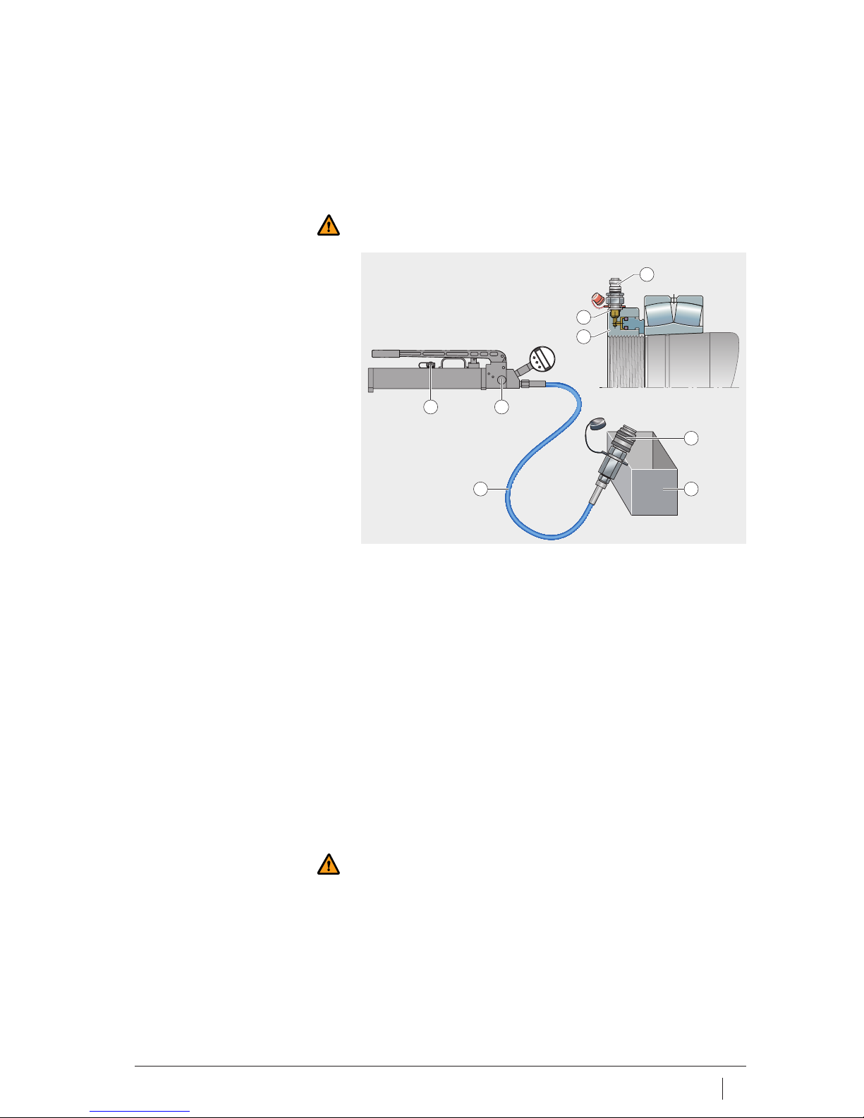
Venting the hand pump Before connecting the hand pump to the hydraulic nut,
vent the hand pump, Figure 6:
■ Provide a collection container
(not included in the delivery)
■ Screw the coupling nipple and sealing ring into
the hydraulic nut
■ Place the hand pump on a rigid, horizontal surface,
since it is only possible to prevent air being sucked in when
the hand pump is horizontal
■ Close the aeration screw completely,
then open it (one revolution)
■ Close the escape valve
■ Hold the high pressure hose vertically upwards
■ Operate the hand pump until oil emerges without air bubbles.
Connection ■ Fit the sleeve on the coupling nipple .
Warning
The high pressure hose must be suitable for a pressure of at least
1000 bar. Do not extend the arm of the hand pump. Check whether
the sleeve and coupling nipple are completely coupled.
Observe a minimum bending radius for the high pressure hose of
70 mm.
Venting the hydraulic nut Operate the hand pump until the hydraulic nut is completely vented,
see BA 004, FAG Hydraulic Nuts.
Coupling nipple
Sealing ring
Hydraulic nut
Sleeve
Collection container (hydraulic oil)
High pressure hose
Escape valve
Aeration screw
Figure 6
Venting the hand pump
78
2
3
1
5
6
4
00015F9C
Page 12
12 BA 20 Schaeffler Group Industrial
Hand pump
Setting the start position The rolling bearing is displaced from the original position to the start
position. The hand pump is of a twin stage design.
At low pressure, a large quantity of oil is pressed into the hydraulic
nut, while above 10 bar this quantity is significantly smaller,
see the section Technical data, page 21.
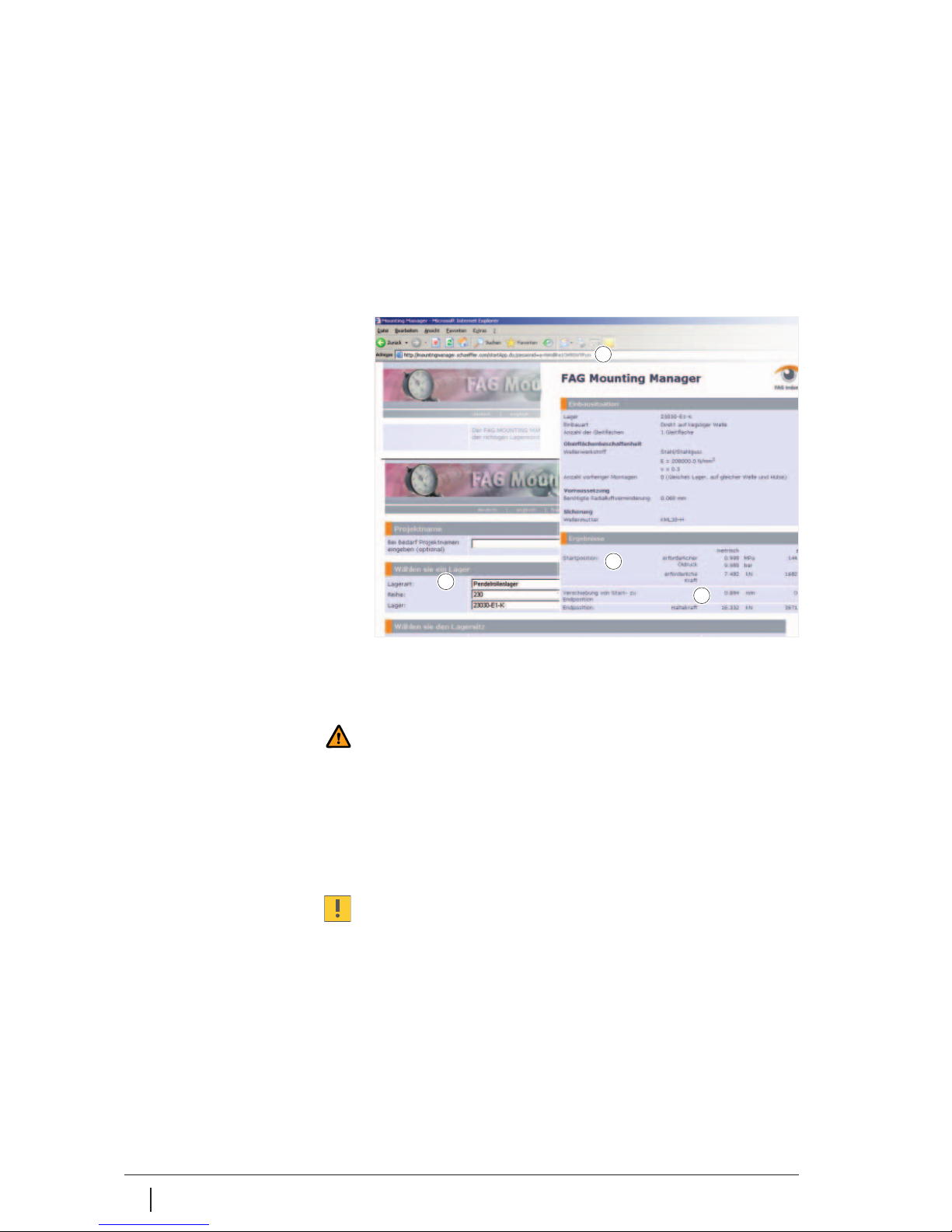
Determining the start pressure The start pressure can be determined, for example,
using the Schaeffler software FAG Mounting Manager.
A user manual for the software is available on the Internet.
After calling up FAG Mounting Manager, the necessary data are
entered, Figure 7. The start pressure for reaching the start position
is then displayed.
Warning
Do not loosen the connectors on the hand pump if the unit is still
pressurised. Do not add any more oil.
Building up the start pressure Once the start pressure has been built up, the rolling bearing is in
the start position, Figure 5, page 10.
Keep the aeration screw open (one revolution):
■ Close the escape valve, Figure 3 , page 8
■ Set the digital manometer to zero, then monitor continuously
■ Operate the hand pump until the start pressure is reached.
Do not exceed the start pressure. If the start pressure is exceeded,
the bearing must be dismounted and then remounted.
Internet address
Designation of bearing
Start pressure
Displacement distance
Figure 7
FAG Mounting Manager
00016047
1
2
3
4
Page 13
Schaeffler Group Industrial BA 20 13
Setting the end position The end position is reached when the rolling bearing has been
moved the displacement distance. The displacement distance can
be read off, for example, in FAG Mounting Manager.
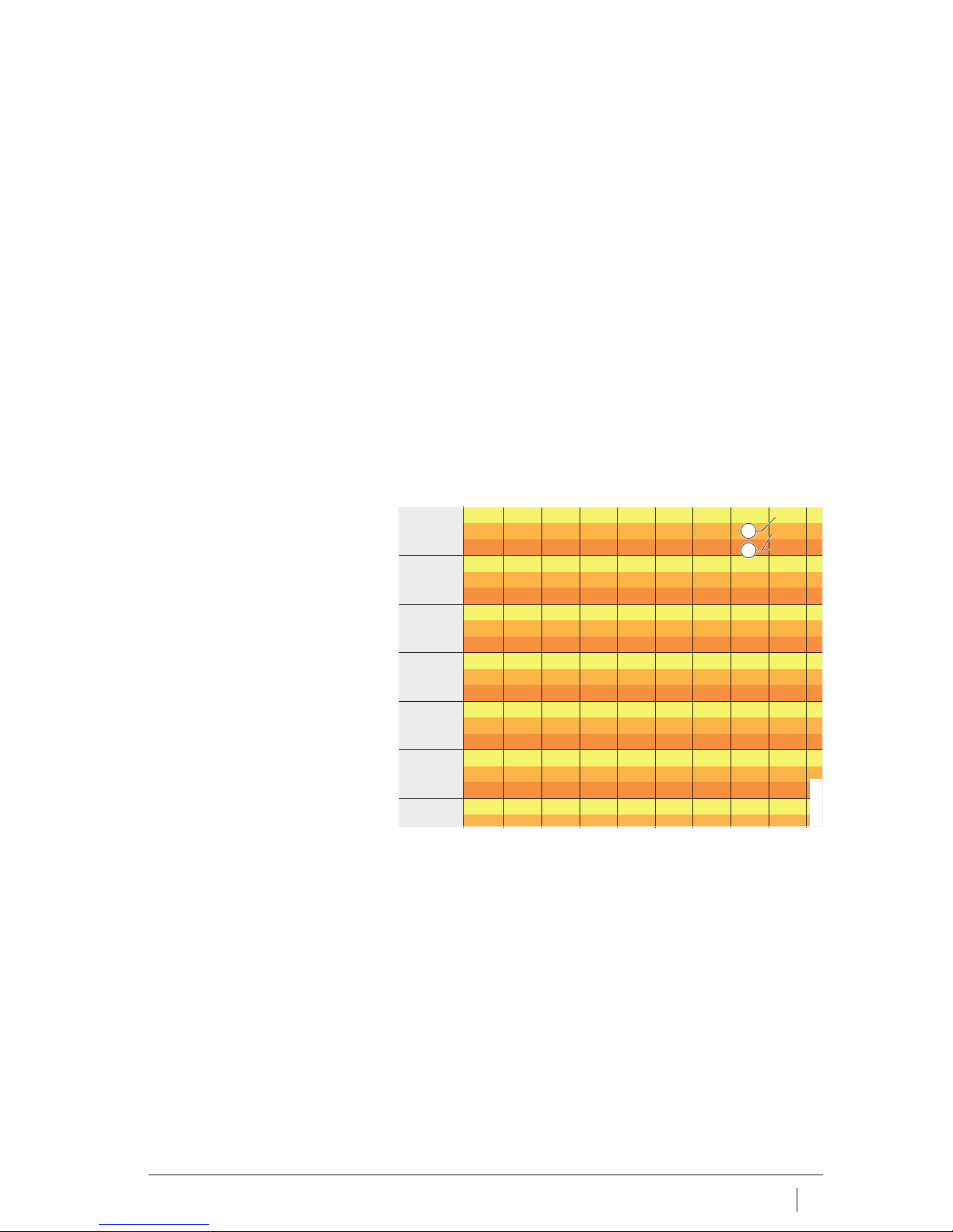
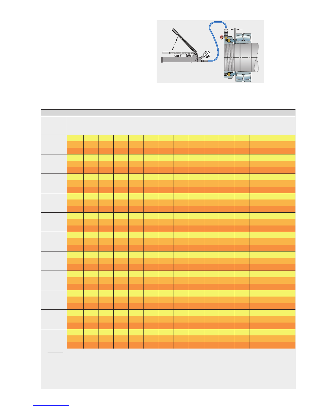
Determining the number of strokes The number of strokes can be read off on the basis of
the displacement distance and the hydraulic nut used, Figure 8,
and the value table, starting from page 24.
Example The following hydraulic nut is used for mounting of bearings:
■ HYDNUT160.
When using HYDNUT160, any spacer ring present must be
dismounted, see the section Spacer ring, page 9.
The software FAG Mounting Manager determines the displacement
distance as follows:
■ 0,94 mm.
The next highest displacement distance is 1,01 mm and the number
of strokes is as follows, see the value table:
■ 10 strokes for mounting with hydraulic support
■ 12 strokes for mounting without hydraulic support.
Next highest displacement distance
Number of strokes
Figure 8
Value table, excerpt
160 s mm 0,52 0,57 0,63 0,69 0,76 0,84 0,92 1,01 1
x1– 5 6 6 7 7 8 9 10 11
x2– 6 7 7 8 9 10 10 12 13
170
s mm 0,55 0,61 0,67 0,73 0,81 0,89 0,97 1,07 1
x1– 6 6 7 8 9 9 10 11 13
x2– 7 7 8 9 10 11 12 13 15
180
s mm 0,57 0,63 0,69 0,76 0,83 0,92 1,01 1,11 1
x1– 7 7 8 9 10 11 12 13 14
x2– 8 8 9 10 11 12 13 15 16
190
s mm 0,61 0,67 0,74 0,81 0,89 0,98 1,08 1,19 1
x1– 8 9 10 10 12 13 14 15 17
x2– 9 10 11 12 13 15 16 18 19
200
s mm 0,64 0,7 0,77 0,85 0,94 1,03 1,13 1,25 1
x1– 9 10 11 12 13 14 16 17 19
x2– 10 11 12 14 15 16 18 20 22
210
s mm 0,7 0,77 0,85 0,93 1,02 1,13 1,24 1,36 1
x1– 11 12 13 14 15 17 19 20 23
x2– 12 13 15 16 18 19 21 23 26
220
s mm 0,7 0,77 0,85 0,93 1,02 1,13 1,24 1,36 1
x
– 11 12 14 15 16 18 20 22 24
1
2
00016064
Page 14
14 BA 20 Schaeffler Group Industrial
Hand pump
Moving the rolling bearing
to the end position
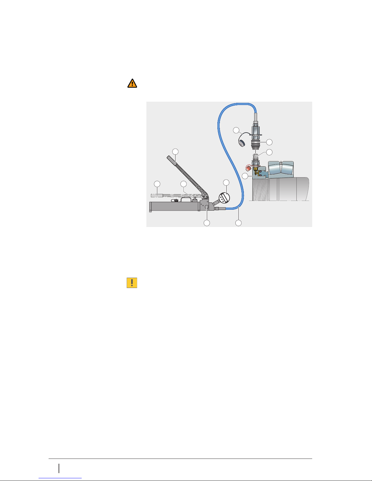
The hand pump is operated to bring the rolling bearing into the end
position, Figure 9.
Warning
800 bar must not be exceeded. Do not loosen the connectors on
the hand pump if the unit is still pressurised.
Do not add any more oil.
Keep the aeration screw open (one revolution):
■ Close the escape valve , set the stroke counter to 0
■ Monitor the digital manometer
■ Move the hand pump from the upper stop to the lower stop
until the stroke counter shows the number of strokes.
Operate the escape valve by hand only. On each occasion,
the arm must be moved up to the upper stop and then down.
Do not exceed the number of strokes. If the number of strokes is
exceeded, the bearing must be dismounted and then moved back
to the start position.
Dismounting the hand pump Before the hand pump is removed, it must be unpressurised.
Releasing the pressure ■ Slowly open the escape valve
■ Monitor the digital manometer .
Removing the hand pump ■ Once the unit is unpressurised, remove the sleeve from
the coupling nipple
■ Close the sleeve using the end cap .
Escape valve
Digital manometer
High pressure hose
End cap
Sleeve
Coupling nipple
Hydraulic nut
Upper stop
Lower stop
Stroke counter
Figure 9
End position, dismounting
2
31
10
7
5
6
8
9
4
00015F9D
Page 15

Schaeffler Group Industrial BA 20 15
Maintenance The use of unsuitable replacement parts and oils can damage
the hand pump and may lead to hazards occurring for the user.
Always use original replacement parts sets from Schaeffler KG.
Only use oils recommended by us, see the section Hydraulic oil,
page 7.
Changing the oil Check the hydraulic oil six months after the last oil change.
Replace contaminated oil.
One year after the last oil change, replace the oil even if it is not
contaminated:
■ Empty the tank completely
■ Check the tank and clean it if necessary
■ Fill the tank completely with fresh oil, pump 50 times,
then fill up with fresh oil.
Note
Dispose of oil, contaminated cloths and similar materials in
the correct manner.
Cleaning the tank Clean the tank if there are stubborn deposits on the walls of
the tank:
■ Empty the tank completely
■ Fill the tank with petroleum ether
■ Rock the filled tank
■ Empty the tank completely
■ Vent the tank.
Note
Dispose of petroleum ether, contaminated cloths and similar
materials in the correct manner.
Page 16
16 BA 20 Schaeffler Group Industrial
Hand pump
Techni ca l data
Hand pump
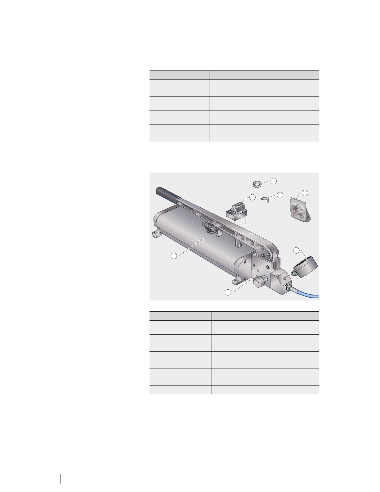
Ordering designations Replacement parts, Figure 10 and
table Ordering designation PUMP1000-4L-CONTROL.
Ordering designation
PUMP1000-4L-CONTROL
Component Technical data
Threaded connector G1/
4
Oil container capacity 4l
Delivery volume ⬍10 bar 4cm3 per stroke with spacer ring (half ring);
18 cm3 per stroke without spacer ring (half ring)
Delivery volume ⬎10 bar 0,2 cm3 per stroke with spacer ring (half ring);
0,9 cm3 per stroke without spacer ring (half ring)
Maximum oil pressure 1000 bar
Mass ⬇ 24 kg (including metal case)
Pump body
Oil container
Digital manometer
Spacer ring (full ring)
Spacer ring (half ring)
Stroke counter
Wear parts (set)
Figure 10
Replacement parts
O
P
E
N
C
L
O
S
E
2
1
3
4
5
6
7
00016066
Component Ordering designation
Complete hand pump PUMP1000-4L-CONTROL
(incl. digital manometer in metal case)
Pump body PUMP1000-4L.BODY
Oil container PUMP1000-4L.TANK
Digital manometer PUMP1000.MANO-DIGI
Spacer ring (full ring) PUMP1000-4L-CONTROL.RING-0,2ML
Spacer ring (half ring) PUMP1000-4L-CONTROL.RING-0,9ML
Stroke counter PUMP1000-4L-CONTROL.COUNTER
Wear parts PUMP1000-4L.SPARE-KIT
Page 17
Schaeffler Group Industrial BA 20 17
Hand pump
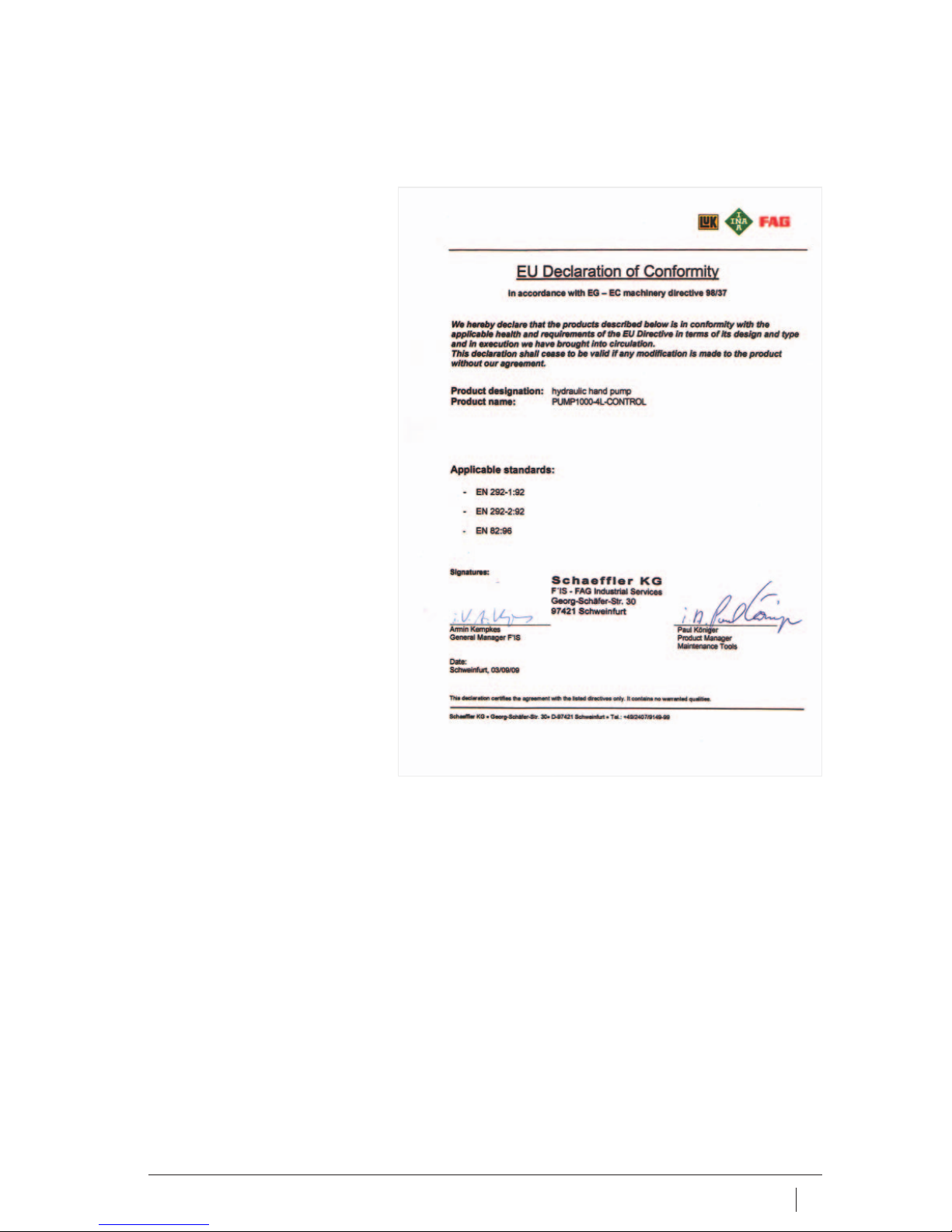
EU Declaration of Conformity Declaration of Conformity for hand pump PUMP1000-4L-CONTROL.
Figure 11
EU Declaration of Conformity
0001645D
Page 18
18 BA 20 Schaeffler Group Industrial
Hand pump
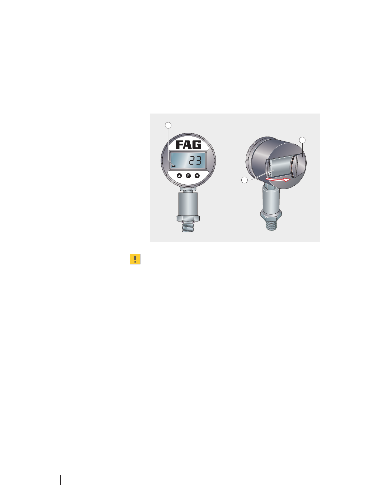
Digital manometer The digital manometer PUMP1000-4L-CONTROL.MANO is part of
the hand pump and is already mounted when the hand pump is
supplied.
Features A ceramic sensor records the pressure and shows the value on
a four digit LED display. The accuracy is 0,5%.
The manometer is powered by a 9 V battery and has a peak value
memory.
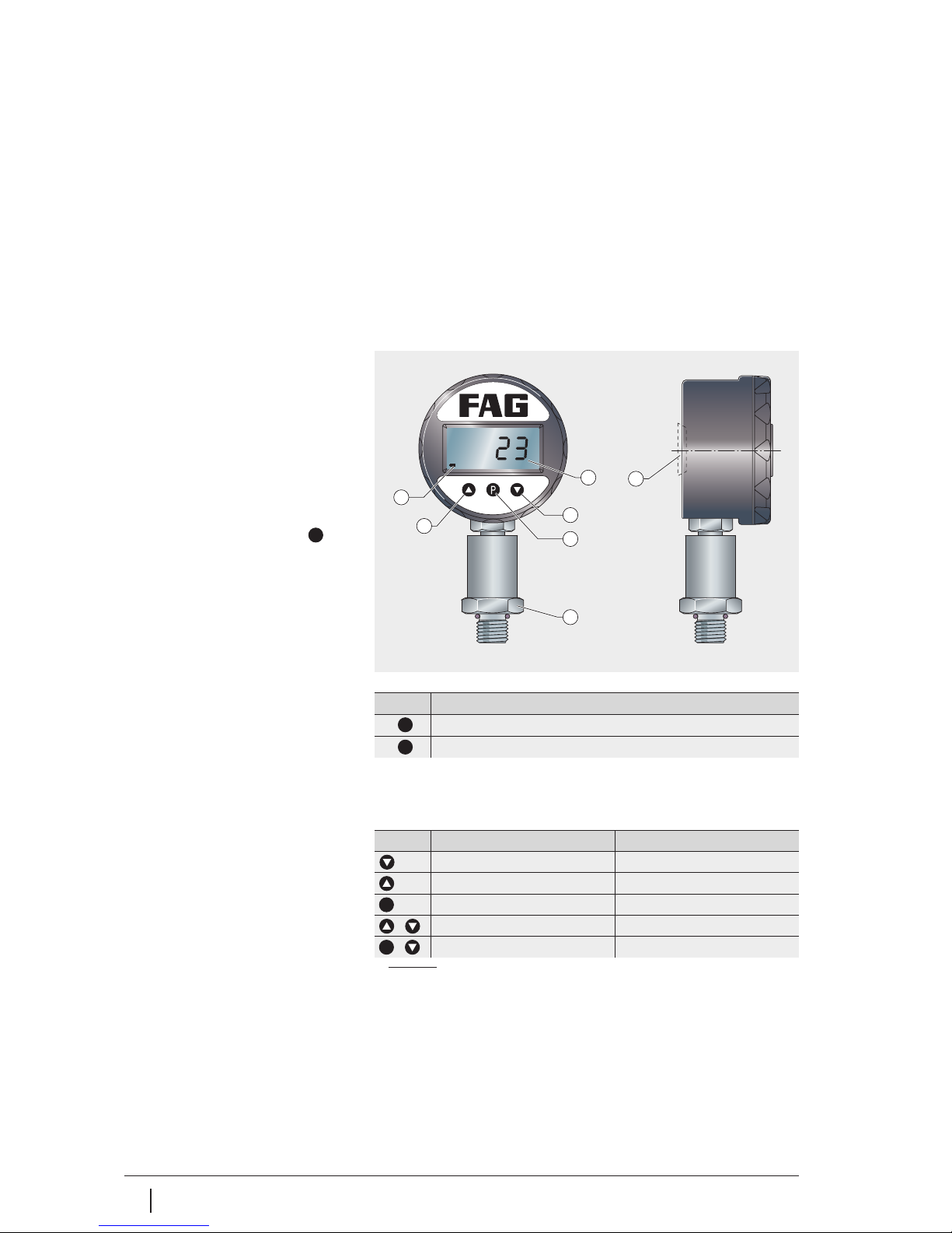
Operation The device is operated using three membrane keys on the front,
Figure 12.
Switching on, switching off
Control keys The specific function of the key depends on whether the user
changes between different menu items or is within a single menu
item, see table.
Function of control keys
1)
When the value is confirmed, the system moves to the next menu item.
LED display
Down key
key
Up key
Battery symbol
Battery compartment cover
Hexagonal nut M27
Figure 12
Digital manometer
P
6
4
5
3
1
2
7
00015F65
Key Function
Device is switched on
2⫻ Device is switched off
P
P
Key Select menu item Set value
Next menu item Reduce value
Previous menu item Increase value
– Confirm value
1)
– Cancel value
Jump to function –
P
&
&
P
Page 19
Schaeffler Group Industrial BA 20 19
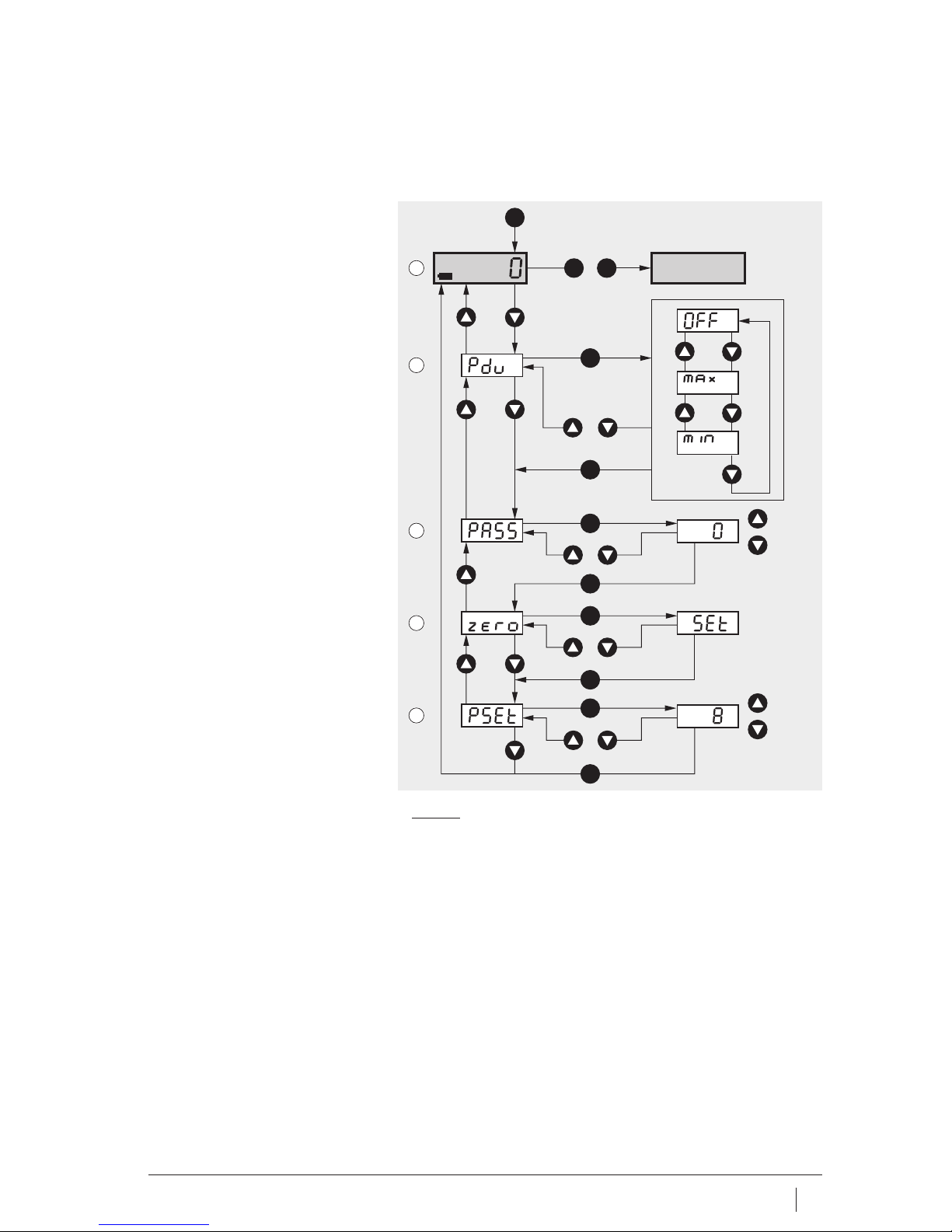
Control diagram The navigation and setting options are shown in the control
diagram, Figure 13.
Footnotes for Figure 13
1)
Peak value memory off.
2)
Recording of maximum values.
3)
Recording of minimum values.
4)
Factory setting = 5.
5)
Automatic zeroing.
6)
New password, example.
LCD display
Peak value memory
Enter password
Automatic zeroing
Change password
Figure 13
Control diagram
&
P
P P
P
P
P
P
P
P
&
&
P
&
P
1⫻P = ON
1
2
3
4
5
2⫻P = OFF
1)
2)
3)
4)
6)
5)
00015F67
Page 20
20 BA 20 Schaeffler Group Industrial
Hand pump
Maintenance Contaminated hydraulic oil can make maintenance necessary at
Schaeffler KG. If clean hydraulic oil is always used, maintenance is
restricted to changing the battery.
Changing the battery If the voltage of the battery falls below 7 Volt, the battery symbol
is shown, Figure 14. Lift the battery cover outwards and change
the battery.
Replace a used battery promptly by a fresh battery if the battery
symbol is shown. Replace a damaged battery cover and seal
promptly, since the ingress of hydraulic oil will destroy the device.
Always mount and dismount the digital manometer using
the hexagonal nut, never the housing, Figure 12, page 18!
Dismounting To replace a digital manometer that is damaged or in need of
maintenance:
■ Ensure that the hand pump is unpressurised
■ Unscrew the digital manometer (right hand thread) using
a wrench (A/F27).
Mounting To mount a new or repaired digital manometer:
■ Use a new sealing ring, Figure 12, page 18
■ Mount the digital manometer (right hand thread) using
a wrench (A/F27).
Battery symbol
Battery cover
9V battery
Figure 14
Changing the battery
1
2
3
00015FA3
Page 21
Schaeffler Group Industrial BA 20 21
Technical data
Digital manometer
Ordering designations
Ordering designation
Digital manometer
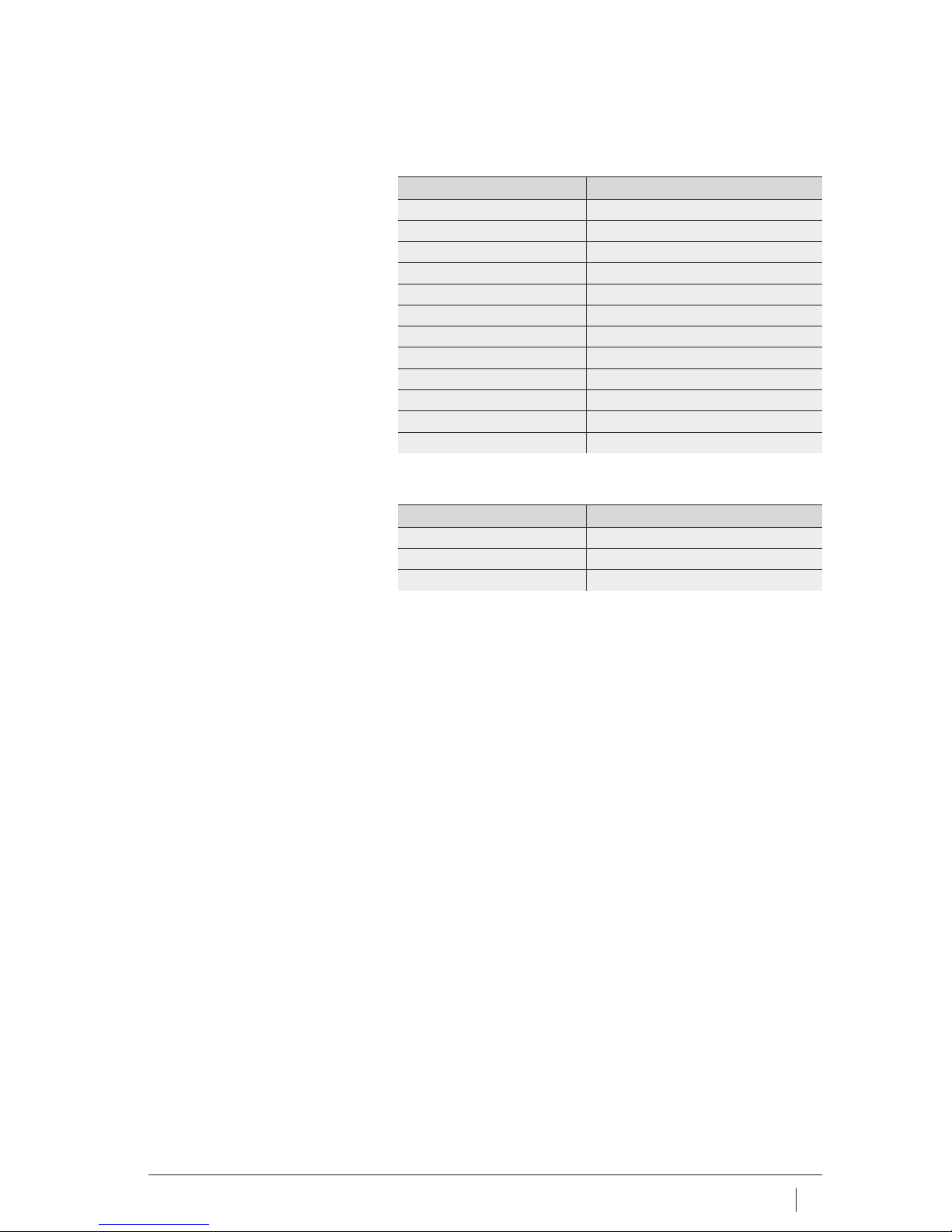
Component Technical data
Threaded connector G3/
4
Accuracy class 0,5%
Zero point correction ⬉25%
Measurement range 0 bar to 1000 bar
Overload range 1500 bar
Power supply 9V
Battery life ⬇ 5 000 h (600 mAh)
Operating temperature 0 °C to +60 °C
Storage temperature –30 °C to +80 °C
Max. relative humidity 90%, no condensation
Protection type IP 65
Mass ⬇ 0,35 kg
Component Ordering designation
Digital manometer PUMP1000-4L-CONTROL.MANO
Sealing ring Flat seal to DIN 16 258
Battery 9V
Page 22
22 BA 20 Schaeffler Group Industrial
Hand pump
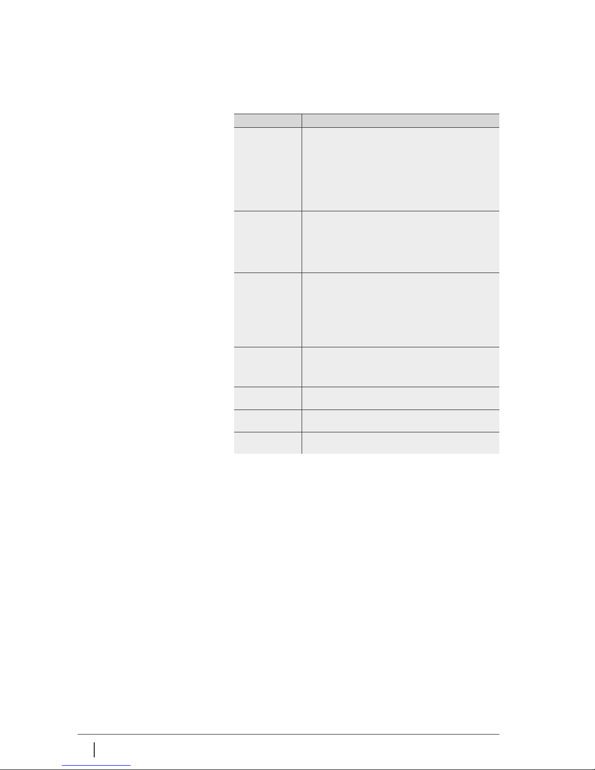
Troubleshooting A list of common malfunctions is shown in the following table.
Malfunction, cause, remedies
Malfunction Cause, remedy
Piston
does not move out
The hand pump was positioned with the head facing up:
■ Position the hand pump with the feet facing down.
The escape valve of the hand pump is not closed or
not completely closed:
■ Close the escape valve.
Leak in the oil circuit:
■ Replace leaking parts or send the hand pump to
Schaeffler KG, Schweinfurt, for repair.
Cylinder
moves out in
a jolting motion or
not completely
Air in the oil circuit:
■ Vent the pump, high pressure hose and hydraulic nut.
The piston of the hydraulic cylinder is bent or damaged
and is being subjected to mechanical braking as a result:
■ Send the hand pump to Schaeffler KG, Schweinfurt,
for repair.
The piston
sinks back under
load
Escape valve leaking:
■ Replace leaking parts or send the hand pump to
Schaeffler KG, Schweinfurt, for repair.
Cylinder seals leaking:
■ Replace the seals.
Leakage at couplings or hose fittings:
■ Replace parts with original replacement parts.
Cylinder does not
move back
completely or
only very slowly
Oil is not flowing freely back into the tank:
■ Check whether the escape valve is completely open
and the nipples and sleeves are correctly coupled.
Continuous
oil loss
Leakage at the pump piston:
■ Replace the seals.
Stroke counter
is not counting
Replace stroke counter.
Manometer
not functioning
Replace the battery.
Page 23

Schaeffler Group Industrial BA 20 23
Page 24
24 BA 20 Schaeffler Group Industrial
Displacement
Number of strokes
s
x , x
12
0000160AD
1)
Spacer ring (half ring) must be mounted.
Value table
Designation s=Displacement
x1= Number of strokes with hydraulic method
x2= Number of strokes without hydraulic method
HYDNUT
50
1)
s mm 0,2 0,22 0,24 0,27 0,29 0,32 0,35 0,39 0,43 0,47 0,52 0,57
x1– 3 3 4 4 5 5 5 6 7 7 8 9
x2– 5 5 5 6 7 7 8 9 10 11 12 13
55
1)
s mm 0,21 0,23 0,25 0,28 0,31 0,34 0,37 0,41 0,45 0,5 0,54 0,6
x1– 3 4 4 4 5 5 6 7 7 8 9 10
x2– 5 5 6 7 7 8 9 10 11 12 13 14
60
1)
s mm 0,23 0,25 0,28 0,31 0,34 0,37 0,41 0,45 0,49 0,54 0,6 0,66
x1– 4 4 4 5 5 6 6 7 8 9 10 10
x2– 5 6 6 7 8 9 9 10 11 12 14 15
65
1)
s mm 0,24 0,26 0,29 0,32 0,35 0,39 0,43 0,47 0,51 0,57 0,62 0,68
x1– 4 5 5 6 6 7 8 9 9 10 11 13
x2– 6 7 8 8 9 10 11 12 14 15 16 18
70
1)
s mm 0,25 0,28 0,3 0,33 0,37 0,4 0,44 0,49 0,54 0,59 0,65 0,71
x1– 5 6 6 7 8 9 9 10 11 12 14 15
x2– 7 8 9 10 11 12 13 15 16 18 19 21
75
1)
s mm 0,27 0,3 0,33 0,36 0,4 0,43 0,48 0,53 0,58 0,64 0,7 0,77
x1– 6 7 7 8 9 10 11 12 13 14 16 17
x2– 8 9 10 11 12 14 15 17 18 20 22 24
80
1)
s mm 0,28 0,31 0,34 0,37 0,41 0,45 0,5 0,55 0,6 0,66 0,73 0,8
x1– 7 8 9 9 10 11 12 14 15 17 18 20
x2– 10 11 12 13 14 16 17 19 21 23 25 28
85
1)
s mm 0,3 0,33 0,36 0,4 0,44 0,48 0,53 0,58 0,64 0,71 0,78 0,86
x1– 7 8 9 10 11 12 13 14 16 17 19 21
x2– 10 11 12 13 15 16 18 20 22 24 26 29
90
1)
s mm 0,31 0,34 0,38 0,41 0,45 0,5 0,55 0,6 0,66 0,73 0,8 0,88
x1– 8 9 9 10 11 13 14 15 17 19 20 22
x2– 11 12 13 14 16 17 19 21 23 25 27 30
95
1)
s mm 0,32 0,35 0,39 0,43 0,47 0,52 0,57 0,62 0,69 0,75 0,83 0,91
x1– 9 9 10 11 12 14 15 17 18 20 22 24
x2– 11 13 14 15 17 18 20 22 24 27 30 32
100
1)
s mm 0,34 0,37 0,41 0,45 0,5 0,55 0,6 0,66 0,73 0,8 0,88 0,97
x1– 9 10 11 12 14 15 17 18 20 22 24 27
x2– 12 14 15 16 18 20 22 24 27 29 32 35
Page 25
Schaeffler Group Industrial BA 20 25
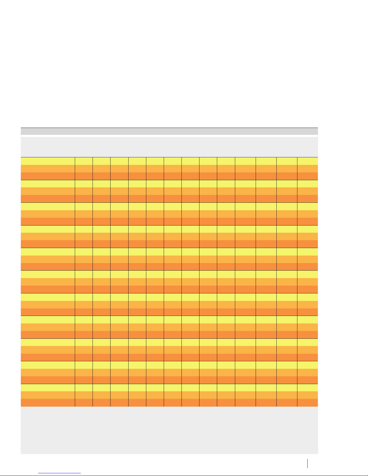
0,63 0,69 0,76 0,84 0,92 1,01 1,11 1,22 1,35 1,48 1,63 1,79 1,97 2,17
10 11 12 13 14 16 17 19 21 23 25 28 30 33
14 16 17 19 21 23 25 28 31 34 37 41 45 49
0,66 0,72 0,8 0,88 0,96 1,06 1,17 1,28 1,41 1,55 1,71 1,88 2,07 2,28
11 12 13 14 15 17 19 21 23 25 27 30 33 37
15 17 19 20 23 25 27 30 33 36 40 44 48 53
0,72 0,79 0,87 0,96 1,06 1,16 1,28 1,41 1,55 1,7 1,87 2,06 2,27 2,49
12 13 14 15 17 19 20 22 25 27 30 33 36 40
17 18 20 22 24 27 29 32 36 39 43 47 52 57
0,75 0,83 0,91 1 1,1 1,21 1,33 1,47 1,61 1,78 1,95 2,15 2,36 2,6
14 15 17 18 20 22 25 27 30 33 36 40 44 48
20 22 24 26 29 32 35 39 42 47 51 56 62 68
0,78 0,86 0,95 1,04 1,15 1,26 1,39 1,53 1,68 1,85 2,04 2,24 2,46 2,71
17 18 20 22 24 27 29 32 36 39 43 47 52 57
23 26 28 31 34 38 41 46 50 55 61 67 73 81
0,85 0,93 1,03 1,13 1,24 1,36 1,5 1,65 1,82 2 2,2 2,42 2,66 2,93
19 21 23 25 28 31 34 37 41 45 49 54 60 66
27 29 32 35 39 43 47 52 57 63 69 76 83 92
0,88 0,97 1,06 1,17 1,29 1,42 1,56 1,71 1,88 2,07 2,28 2,51 2,76 3,03
22 24 27 29 32 36 39 43 47 52 57 63 69 76
30 33 37 41 45 49 54 59 65 72 79 87 96 105
0,94 1,04 1,14 1,25 1,38 1,52 1,67 1,83 2,02 2,22 2,44 2,69 2,95 3,25
23 26 28 31 34 38 41 45 50 55 60 66 73 80
32 35 38 42 47 51 56 62 68 75 82 91 100 110
0,97 1,07 1,18 1,29 1,42 1,57 1,72 1,9 2,09 2,29 2,52 2,78 3,05 3,36
25 27 30 33 36 40 44 48 53 58 64 70 77 85
33 37 40 44 49 54 59 65 71 78 86 95 104 115
1 1,1 1,22 1,34 1,47 1,62 1,78 1,96 2,15 2,37 2,6 2,87 3,15 3,47
27 29 32 36 39 43 47 52 57 63 69 76 84 92
36 39 43 48 52 58 63 70 77 84 93 102 112 123
1,07 1,17 1,29 1,42 1,56 1,72 1,89 2,08 2,29 2,52 2,77 3,04 3,35 3,68
29 32 36 39 43 47 52 57 63 69 76 84 92 102
39 43 47 52 57 63 69 76 83 92 101 111 122 134
Page 26
26 BA 20 Schaeffler Group Industrial
Displacement
Number of strokes
s
x , x
12
0000160AD
1)
Spacer ring (half ring) must be mounted.
Value table (continued)
Designation s=Displacement
x1= Number of strokes with hydraulic method
x2= Number of strokes without hydraulic method
HYDNUT
105
1)
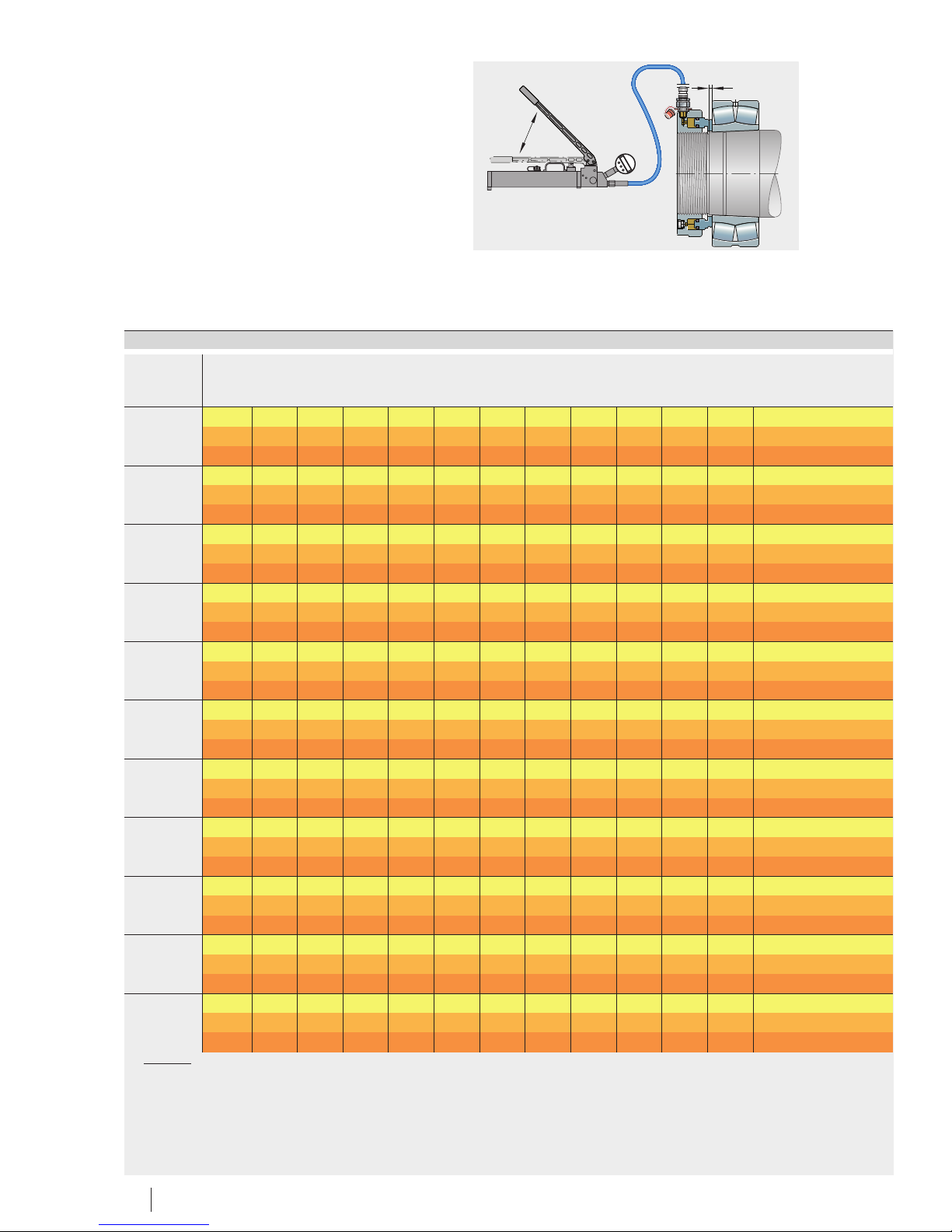
s mm 0,38 0,42 0,46 0,51 0,56 0,61 0,67 0,74 0,81 0,9 0,99 1,08
x1– 11 12 13 15 16 18 19 21 24 26 28 31
x2– 14 16 17 19 21 23 25 28 31 34 37 41
110
1)
s mm 0,37 0,41 0,45 0,49 0,54 0,6 0,66 0,72 0,79 0,87 0,96 1,06
x1– 11 12 13 15 16 18 19 21 24 26 29 31
x2– 14 15 17 19 20 23 25 27 30 33 36 40
115
1)
s mm 0,46 0,51 0,56 0,61 0,67 0,74 0,81 0,9 0,99 1,08 1,19 1,31
x1– 14 16 17 19 21 23 25 27 30 33 37 40
x2– 18 19 21 23 26 28 31 34 38 42 46 50
120
1)
s mm 0,4 0,44 0,48 0,53 0,59 0,64 0,71 0,78 0,86 0,94 1,04 1,14
x1– 13 14 15 17 19 20 23 25 27 30 33 36
x2– 16 17 19 21 23 25 28 30 33 37 40 44
125
1)
s mm 0,48 0,53 0,58 0,64 0,7 0,77 0,85 0,94 1,03 1,13 1,24 1,37
x1– 16 17 19 21 23 26 28 31 34 37 41 45
x2– 19 21 23 25 28 31 34 37 41 45 49 54
130
1)
s mm 0,42 0,46 0,51 0,56 0,61 0,68 0,74 0,82 0,9 0,99 1,09 1,2
x1– 14 15 17 19 20 22 25 27 30 33 36 40
x2– 17 18 20 22 24 27 30 32 36 39 43 48
135
1)
s mm 0,51 0,56 0,62 0,68 0,75 0,82 0,9 0,99 1,09 1,2 1,32 1,46
x1– 17 19 21 23 25 28 31 34 37 41 45 49
x2– 21 23 25 27 30 33 36 40 44 48 53 59
140
1)
s mm 0,45 0,5 0,54 0,6 0,66 0,72 0,8 0,88 0,96 1,06 1,17 1,28
x1– 14 15 16 18 20 22 24 26 29 32 35 39
x2– 16 18 19 21 23 26 28 31 34 38 42 46
145
1)
s mm 0,55 0,61 0,67 0,73 0,81 0,89 0,97 1,07 1,18 1,3 1,43 1,57
x1– 20 22 24 26 29 32 35 38 42 46 51 56
x2– 23 25 28 31 34 37 41 45 49 54 60 66
150
1)
s mm 0,49 0,54 0,59 0,65 0,72 0,79 0,87 0,95 1,05 1,16 1,27 1,4
x1– 19 21 23 25 27 30 33 36 40 44 48 53
x2– 22 24 26 29 32 35 39 42 47 51 57 62
155 s mm 0,51 0,56 0,62 0,68 0,75 0,82 0,91 1 1,1 1,21 1,33 1,46
x1– 5 5 6 6 7 8 8 9 10 11 12 13
x2– 5 6 7 7 8 9 10 11 12 13 14 16
Page 27
Schaeffler Group Industrial BA 20 27
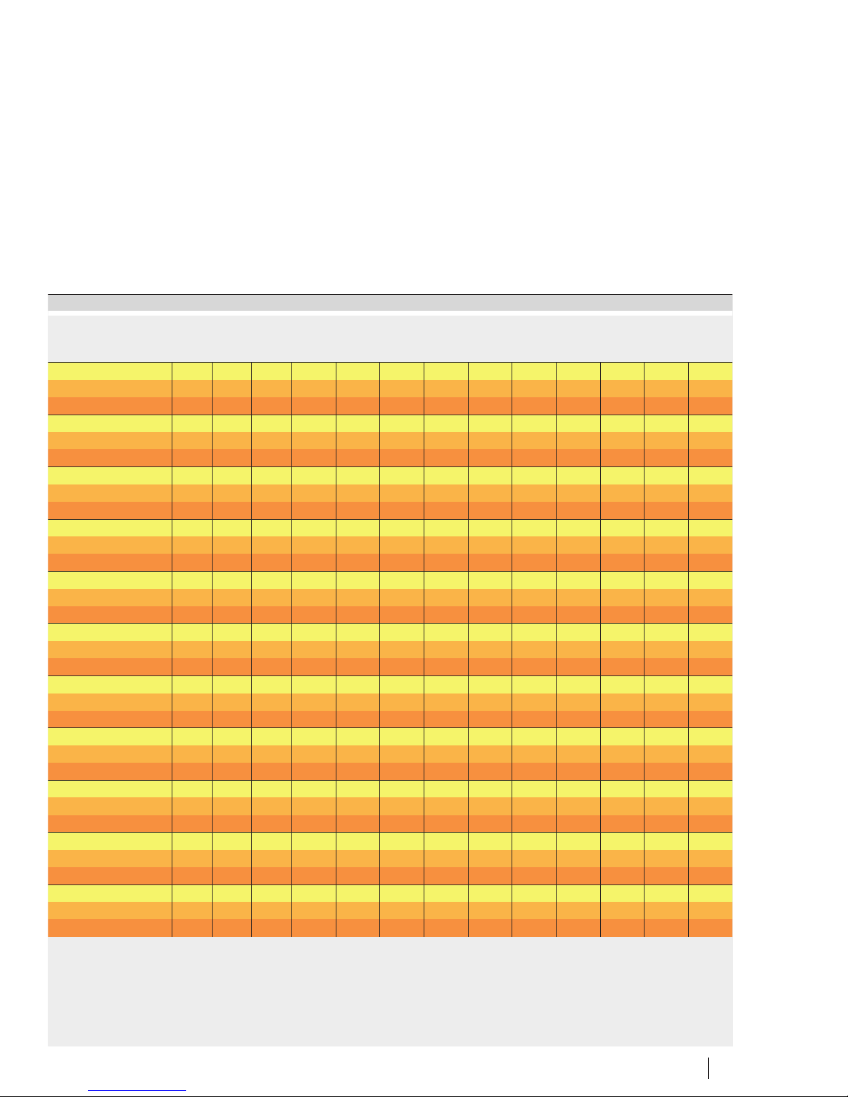
1,19 1,31 1,44 1,59 1,75 1,92 2,11 2,32 2,56 2,81 3,09 3,4 3,74 4,12
34 38 42 46 50 56 61 67 74 81 89 98 108 119
45 49 54 59 65 72 79 87 96 105 116 127 140 154
1,16 1,28 1,41 1,55 1,7 1,87 2,06 2,26 2,49 2,74 3,01 3,31 3,64 4,01
35 38 42 46 51 56 61 67 74 81 90 99 108 119
44 48 53 58 64 71 78 86 94 104 114 125 138 152
1,44 1,59 1,75 1,92 2,11 2,33 2,56 2,81 3,09 3,4 3,74 4,12 4,53 4,98
44 49 54 59 65 71 78 86 95 104 115 126 139 153
55 61 67 74 81 89 98 108 118 130 143 158 173 191
1,26 1,38 1,52 1,67 1,84 2,02 2,22 2,45 2,69 2,96 3,26 3,58 3,94 4,33
40 44 48 53 58 64 71 78 86 94 104 114 125 138
49 54 59 65 72 79 87 95 105 115 127 139 153 169
1,51 1,66 1,82 2,01 2,21 2,43 2,67 2,94 3,23 3,55 3,91 4,3 4,73 5,2
50 55 60 66 73 80 88 97 107 118 129 142 157 172
60 66 72 80 88 96 106 117 128 141 155 171 188 207
1,32 1,45 1,59 1,75 1,93 2,12 2,34 2,57 2,83 3,11 3,42 3,76 4,14 4,55
44 48 53 58 64 70 78 85 94 103 113 125 137 151
52 58 63 70 77 84 93 102 112 123 136 149 164 181
4,6 1,76 1,94 2,13 2,34 2,58 2,84 3,12 3,43 3,77 4,15 4,57 5,02 5,53
54 60 66 72 79 87 96 106 116 128 141 155 170 187
65 71 78 86 95 104 114 126 138 152 167 184 203 223
1,41 1,55 1,71 1,88 2,07 2,27 2,5 2,75 3,03 3,33 3,66 4,03 4,43 4,88
42 47 51 57 62 68 75 83 91 100 110 121 133 147
50 55 61 67 74 81 89 98 108 119 131 144 158 174
1,73 1,9 2,09 2,3 2,53 2,78 3,06 3,36 3,7 4,07 4,48 4,92 5,42 5,96
61 68 74 82 90 99 109 120 132 145 159 175 193 212
72 80 88 96 106 117 128 141 155 171 188 207 227 250
1,54 1,69 1,86 2,05 2,25 2,48 2,72 3 3,3 3,63 3,99 4,39 4,83 5,31
58 64 71 78 86 94 104 114 125 138 152 167 184 202
68 75 83 91 100 110 121 133 147 161 177 195 215 236
1,61 1,77 1,94 2,14 2,35 2,59 2,84 3,13 3,44 3,78 4,16 4,58 5,04 5,54
15 16 18 19 21 24 26 29 31 35 38 42 46 51
17 19 21 23 25 28 30 33 37 40 44 49 54 59
Page 28
28 BA 20 Schaeffler Group Industrial
Displacement
Number of strokes
s
x , x
12
0000160AD
Value table (continued)
Designation s=Displacement
x1= Number of strokes with hydraulic method
x2= Number of strokes without hydraulic method
HYDNUT
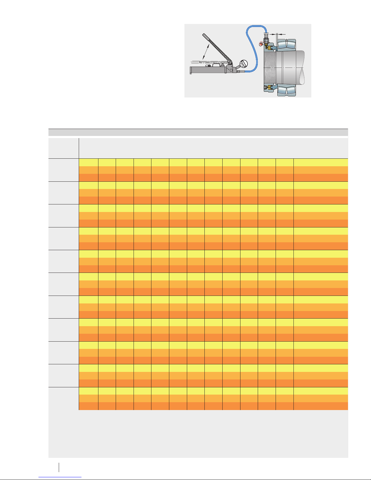
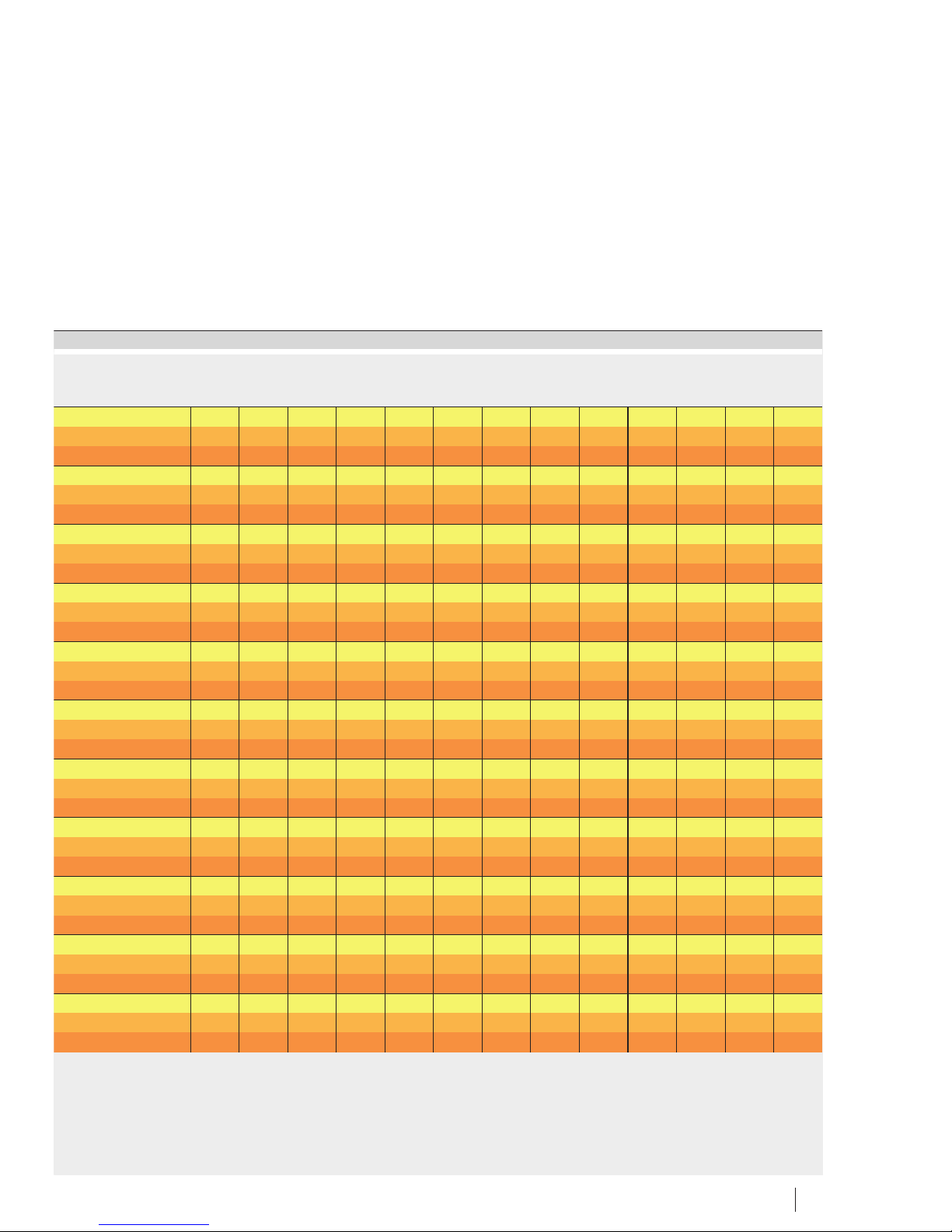
160 s mm 0,52 0,57 0,63 0,69 0,76 0,84 0,92 1,01 1,11 1,23 1,35 1,48
x1– 5 6 6 7 7 8 9 10 11 12 13 15
x2– 6 7 7 8 9 10 10 12 13 14 15 17
170 s mm 0,55 0,61 0,67 0,73 0,81 0,89 0,97 1,07 1,18 1,3 1,43 1,57
x1– 6 6 7 8 9 9 10 11 13 14 15 17
x2– 7 7 8 9 10 11 12 13 15 16 18 19
180 s mm 0,57 0,63 0,69 0,76 0,83 0,92 1,01 1,11 1,22 1,34 1,48 1,63
x1– 7 7 8 9 10 11 12 13 14 16 17 19
x2– 8 8 9 10 11 12 13 15 16 18 20 22
190 s mm 0,61 0,67 0,74 0,81 0,89 0,98 1,08 1,19 1,31 1,44 1,58 1,74
x1– 8 9 10 10 12 13 14 15 17 19 20 22
x2– 9 10 11 12 13 15 16 18 19 21 23 26
200 s mm 0,64 0,7 0,77 0,85 0,94 1,03 1,13 1,25 1,37 1,51 1,66 1,83
x1– 9 10 11 12 13 14 16 17 19 21 23 25
x2– 10 11 12 14 15 16 18 20 22 24 26 29
210 s mm 0,7 0,77 0,85 0,93 1,02 1,13 1,24 1,36 1,5 1,65 1,82 2
x1– 11 12 13 14 15 17 19 20 23 25 27 30
x2– 12 13 15 16 18 19 21 23 26 28 31 34
220 s mm 0,7 0,77 0,85 0,93 1,02 1,13 1,24 1,36 1,5 1,65 1,82 2
x1– 11 12 14 15 16 18 20 22 24 27 29 32
x2– 13 14 16 17 19 21 23 25 27 30 33 37
230 s mm 0,76 0,84 0,92 1,01 1,11 1,22 1,35 1,48 1,63 1,79 1,97 2,17
x1– 14 15 16 18 20 22 24 26 29 32 35 39
x2– 15 17 19 20 23 25 27 30 33 36 40 44
240 s mm 0,76 0,84 0,92 1,01 1,11 1,22 1,35 1,48 1,63 1,79 1,97 2,17
x1– 14 15 17 19 21 23 25 27 30 33 36 40
x2– 16 17 19 21 23 26 28 31 34 37 41 45
250 s mm 1,37 1,51 1,66 1,82 2,01 2,21 2,43 2,67 2,94 3,23 3,55 3,91
x1– 28 31 34 37 41 45 49 54 60 65 72 79
x2– 31 35 38 42 46 51 56 61 67 74 81 90
260 s mm 0,82 0,9 0,99 1,09 1,2 1,32 1,45 1,6 1,76 1,93 2,13 2,34
x1– 17 19 21 23 25 28 30 34 37 41 45 49
x2– 19 21 23 26 28 31 34 38 42 46 50 55
Page 29
Schaeffler Group Industrial BA 20 29
1,63 1,8 1,97 2,17 2,39 2,63 2,89 3,18 3,5 3,85 4,23 4,66 5,12 5,63
16 18 19 21 23 26 28 31 34 38 41 46 50 55
19 20 23 25 27 30 33 36 40 44 48 53 58 64
1,73 1,9 2,09 2,3 2,53 2,78 3,06 3,36 3,7 4,07 4,48 4,92 5,42 5,96
18 20 22 24 27 30 33 36 39 43 48 52 58 63
21 23 26 28 31 34 38 42 46 50 55 61 67 74
1,79 1,97 2,16 2,38 2,62 2,88 3,17 3,49 3,83 4,22 4,64 5,1 5,61 6,18
21 23 25 28 30 33 37 40 45 49 54 59 65 72
24 26 29 32 35 38 42 47 51 56 62 68 75 82
1,91 2,11 2,32 2,55 2,8 3,08 3,39 3,73 4,1 4,51 4,97 5,46 6,01 6,61
25 27 30 33 36 40 44 48 53 58 64 70 77 85
28 31 34 38 41 46 50 55 61 67 73 81 89 98
2,01 2,21 2,43 2,67 2,94 3,23 3,56 3,91 4,31 4,74 5,21 5,73 6,3 6,93
28 31 34 37 41 45 49 54 60 66 72 80 88 96
32 35 39 43 47 51 57 62 68 75 83 91 100 110
2,2 2,42 2,66 2,92 3,22 3,54 3,89 4,28 4,71 5,18 5,7 6,27 6,89 7,58
33 36 40 44 48 53 58 64 71 78 85 94 103 114
38 41 46 50 55 61 67 73 81 89 98 107 118 130
2,2 2,42 2,66 2,92 3,22 3,54 3,89 4,28 4,71 5,18 5,7 6,27 6,89 7,58
35 39 43 47 52 57 63 69 76 83 92 101 111 122
40 44 49 54 59 65 71 78 86 95 104 115 126 139
2,39 2,62 2,89 3,17 3,49 3,84 4,23 4,65 5,11 5,62 6,19 6,81 7,49 8,23
43 47 51 57 62 68 75 83 91 100 110 121 133 147
48 53 58 64 71 78 86 94 104 114 125 138 152 167
2,39 2,62 2,89 3,17 3,49 3,84 4,23 4,65 5,11 5,62 6,19 6,81 7,49 8,23
44 48 53 59 64 71 78 86 94 104 114 126 138 152
50 55 60 66 73 80 88 97 107 118 129 142 157 172
4,3 4,73 5,2 5,72 6,3 6,92 7,62 8,38 9,22 10,14 11,15 12,27 13,49 14,84
87 96 105 116 128 140 154 170 187 206 226 249 274 301
99 108 119 131 144 159 175 192 211 232 255 281 309 340
2,57 2,83 3,11 3,43 3,77 4,14 4,56 5,02 5,52 6,07 6,68 7,34 8,08 8,88
54 59 65 72 79 87 96 105 116 127 140 154 170 186
61 67 74 81 89 98 108 119 130 144 158 174 191 210
Page 30
30 BA 20 Schaeffler Group Industrial
Displacement
Number of strokes
s
x , x
12
0000160AD
Value table (continued)
Designation s=Displacement
x1= Number of strokes with hydraulic method
x2= Number of strokes without hydraulic method
HYDNUT
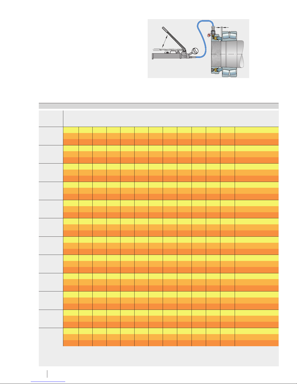
275 s mm 1,47 1,62 1,78 1,96 2,15 2,37 2,6 2,86 3,15 3,47 3,81 4,19
x1– 33 37 40 44 49 54 59 65 72 79 87 95
x2– 38 41 45 50 55 60 66 73 80 88 97 107
280 s mm 0,87 0,96 1,05 1,16 1,27 1,4 1,54 1,7 1,86 2,05 2,26 2,48
x1– 20 23 25 27 30 33 36 40 44 48 53 58
x2– 23 25 28 31 34 37 41 45 49 54 60 65
290 s mm 1,37 1,51 1,66 1,83 2,01 2,21 2,44 2,68 2,95 3,24 3,57 3,92
x1– 33 37 40 44 49 54 59 65 72 79 87 95
x2– 37 41 45 50 55 60 66 73 80 88 97 107
295 s mm 1,55 1,71 1,88 2,06 2,27 2,5 2,75 3,02 3,32 3,65 4,02 4,42
x1– 40 44 48 53 58 64 70 77 85 94 103 113
x2– 44 49 54 59 65 71 79 87 95 105 115 127
300 s mm 0,93 1,02 1,13 1,24 1,36 1,5 1,65 1,81 1,99 2,19 2,41 2,65
x1– 25 27 30 33 36 39 43 48 53 58 64 70
x2– 27 30 33 36 40 44 48 53 59 64 71 78
310 s mm 1,43 1,57 1,73 1,9 2,09 2,3 2,53 2,78 3,06 3,37 3,7 4,07
x1– 40 43 48 53 58 64 70 77 85 93 102 113
x2– 44 48 53 59 64 71 78 86 94 104 114 126
315 s mm 1,67 1,84 2,02 2,22 2,45 2,69 2,96 3,25 3,58 3,94 4,33 4,76
x1– 47 52 57 62 69 76 83 91 101 111 122 134
x2– 52 57 63 69 76 84 92 102 112 123 135 149
320 s mm 1,32 1,45 1,6 1,76 1,93 2,13 2,34 2,57 2,83 3,11 3,42 3,77
x1– 39 43 47 52 57 62 69 75 83 91 100 110
x2– 43 47 52 57 63 69 76 84 92 101 112 123
335 s mm 1,76 1,94 2,13 2,34 2,58 2,83 3,12 3,43 3,77 4,15 4,56 5,02
x1– 54 59 65 72 79 87 95 105 115 127 139 153
x2– 60 66 72 79 87 96 106 116 128 141 155 170
340 s mm 1,4 1,54 1,69 1,86 2,05 2,25 2,48 2,73 3 3,3 3,63 3,99
x1– 44 49 54 59 65 71 79 86 95 105 115 126
x2– 49 54 59 65 72 79 87 96 105 116 127 140
355 s mm 1,85 2,04 2,24 2,46 2,71 2,98 3,28 3,61 3,97 4,36 4,8 5,28
x1– 63 69 76 83 92 101 111 122 134 148 162 178
x2– 69 76 84 92 101 111 122 135 148 163 179 197
360 s mm 1,48 1,63 1,79 1,97 2,17 2,38 2,62 2,88 3,17 3,49 3,84 4,22
x1– 52 57 62 69 76 83 91 101 111 122 134 147
x2– 57 63 69 76 83 92 101 111 122 134 148 162
Page 31
Schaeffler Group Industrial BA 20 31
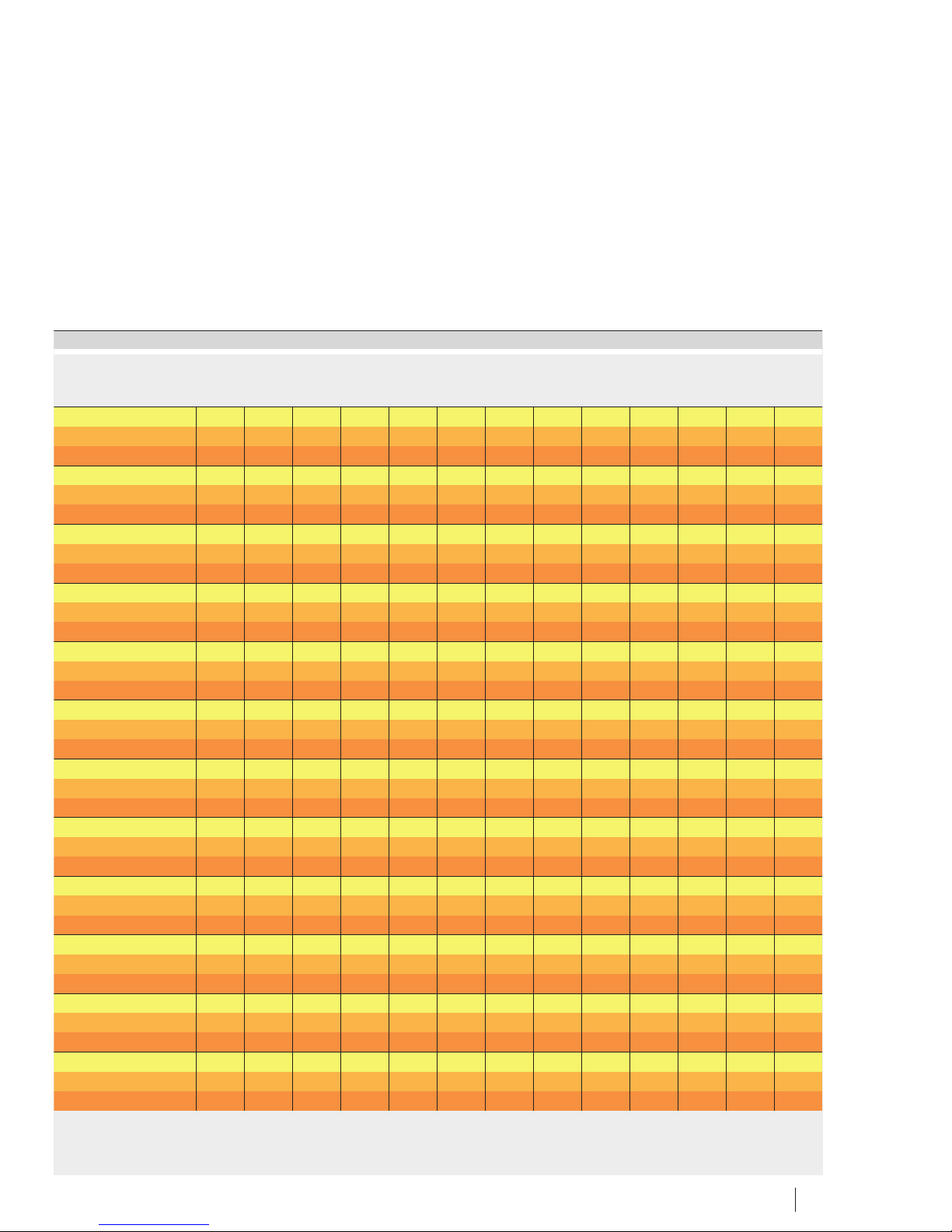
4,61 5,07 5,58 6,14 6,75 7,43 8,17 8,99 9,89 10,88 11,97 13,16 14,48 15,93
105 115 127 139 153 169 186 204 225 247 272 299 329 362
118 129 142 157 172 190 209 229 252 278 305 336 369 406
2,73 3 3,3 3,63 4 4,4 4,84 5,32 5,85 6,44 7,08 7,79 8,57 9,43
64 71 78 86 94 104 114 125 138 152 167 183 202 222
72 79 87 96 105 116 128 140 154 170 187 205 226 249
4,32 4,75 5,22 5,74 6,32 6,95 7,64 8,41 9,25 10,17 11,19 12,31 13,54 14,9
105 115 127 140 154 169 186 204 225 247 272 299 329 362
117 129 142 156 172 189 208 229 252 277 304 335 368 405
4,86 5,35 5,89 6,47 7,12 7,83 8,62 9,48 10,43 11,47 12,62 13,88 15,27 16,79
125 137 151 166 183 201 221 243 267 294 323 356 391 431
139 153 169 185 204 224 247 271 299 329 361 398 437 481
2,92 3,21 3,53 3,88 4,27 4,7 5,17 5,69 6,26 6,88 7,57 8,33 9,16 10,08
77 85 93 102 113 124 136 150 165 181 200 220 241 266
86 94 104 114 126 138 152 167 184 202 223 245 269 296
4,48 4,93 5,42 5,96 6,56 7,22 7,94 8,73 9,6 10,56 11,62 12,78 14,06 15,47
124 136 150 165 182 200 220 242 266 292 322 354 389 428
138 152 167 184 202 223 245 269 296 326 358 394 434 477
5,24 5,77 6,34 9,98 7,67 8,44 9,29 10,21 11,23 12,36 13,59 14,95 16,45 18,09
147 162 178 196 216 237 261 287 316 347 382 420 462 508
164 180 198 218 240 264 290 319 351 386 425 467 514 566
4,14 4,56 5,01 5,51 6,07 6,67 7,34 8,07 8,88 9,77 10,75 11,82 13 14,3
122 134 147 162 178 196 215 237 260 287 315 347 381 420
135 149 163 180 198 218 239 263 290 318 350 385 424 466
5,52 6,08 6,68 7,35 8,09 8,9 9,79 10,76 11,84 13,02 14,33 15,76 17,34 19,07
169 186 204 225 247 272 299 329 362 398 438 482 530 583
187 206 227 249 274 302 332 365 402 442 486 535 588 647
4,39 4,83 5,32 5,85 6,43 7,08 7,78 8,56 9,42 10,36 11,4 12,54 13,79 15,17
139 153 168 185 204 224 247 271 298 328 361 397 437 480
154 170 186 205 226 248 273 300 330 363 400 440 484 532
5,81 6,39 7,03 7,73 8,5 9,35 10,29 11,31 12,45 13,69 15,06 16,57 18,22 20,04
196 216 238 261 287 316 348 383 421 463 509 560 616 678
217 239 263 289 318 349 384 423 465 512 563 619 681 749
4,64 5,11 5,62 6,18 6,8 7,48 8,23 9,05 9,96 10,95 12,05 13,25 14,58 16,04
162 178 196 216 237 261 287 316 347 382 420 462 508 559
179 196 216 238 261 288 316 348 383 421 463 510 560 616
Page 32
32 BA 20 Schaeffler Group Industrial
Displacement
Number of strokes
s
x , x
12
0000160AD
Value table (continued)
Designation s=Displacement
x1= Number of strokes with hydraulic method
x2= Number of strokes without hydraulic method
HYDNUT
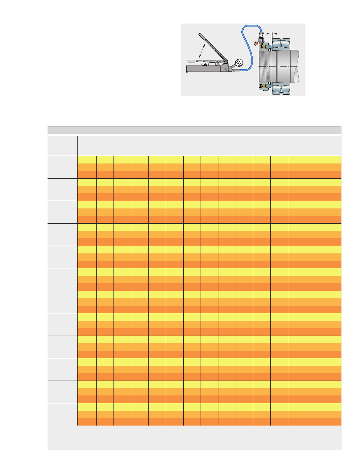
375 s mm 1,94 2,13 2,35 2,58 2,84 3,12 3,44 3,78 4,16 4,57 5,03 5,54
x1– 72 79 87 96 106 116 128 141 155 170 187 206
x2– 79 87 96 106 116 128 141 155 170 187 206 227
380 s mm 1,54 1,69 1,86 2,05 2,25 2,48 2,73 3 3,3 3,63 3,99 4,39
x1– 58 63 70 77 84 93 102 112 124 136 150 165
x2– 63 70 77 84 93 102 112 124 136 150 164 181
395 s mm 2,07 2,28 2,5 2,76 3,03 3,33 3,67 4,03 4,44 4,88 5,37 5,91
x1– 82 90 99 109 120 132 145 160 176 194 213 234
x2– 90 99 109 120 132 145 160 176 193 213 234 257
400 s mm 1,64 1,8 1,98 2,18 2,4 2,64 2,91 3,2 3,52 3,87 4,25 4,68
x1– 67 74 81 89 98 108 119 131 144 158 174 191
x2– 74 81 89 98 108 118 130 143 158 173 191 210
415 s mm 2,17 2,39 2,63 2,89 3,18 3,49 3,84 4,23 4,65 5,12 5,63 6,19
x1– 93 102 113 124 136 150 165 181 200 219 241 266
x2– 102 112 123 136 149 164 181 199 219 240 264 291
420 s mm 1,69 1,86 2,04 2,25 2,47 2,72 2,99 3,29 3,62 3,98 4,38 4,82
x1– 73 81 89 98 107 118 130 143 157 173 190 209
x2– 80 88 97 107 118 129 142 157 172 189 208 229
435 s mm 2,26 2,49 2,73 3,01 3,31 3,64 4 4,4 4,84 5,33 5,86 6,45
x1– 101 111 122 135 148 163 179 197 217 239 262 289
x2– 111 122 134 147 162 178 196 216 237 261 287 316
440 s mm 1,79 1,97 2,17 2,38 2,62 2,88 3,17 3,49 3,84 4,22 4,64 5,11
x1– 85 93 102 113 124 136 150 165 181 200 220 242
x2– 92 102 112 123 135 149 164 180 198 218 240 264
460 s mm 1,85 2,04 2,24 2,46 2,71 2,98 3,28 3,61 3,97 4,36 4,8 5,28
x1– 93 102 112 124 136 150 164 181 199 219 241 265
x2– 101 111 123 135 148 163 179 197 217 239 263 289
480 s mm 1,92 2,11 2,32 2,56 2,81 3,09 3,4 3,74 4,12 4,53 4,98 5,48
x1– 99 108 119 131 144 159 175 192 211 232 256 281
x2– 107 118 130 143 157 173 190 209 230 253 279 307
500 s mm 2,01 2,21 2,43 2,68 2,94 3,24 3,56 3,92 4,31 4,74 5,21 5,73
x1– 117 129 142 156 171 189 207 228 251 276 304 334
x2– 127 140 154 170 187 205 226 248 273 301 331 364
520 s mm 2,67 2,94 3,23 3,55 3,91 4,3 4,73 5,2 5,72 6,3 6,93 7,62
x1– 161 177 195 215 236 260 286 314 346 380 418 460
x2– 175 193 212 233 257 282 311 342 376 414 455 500
Page 33
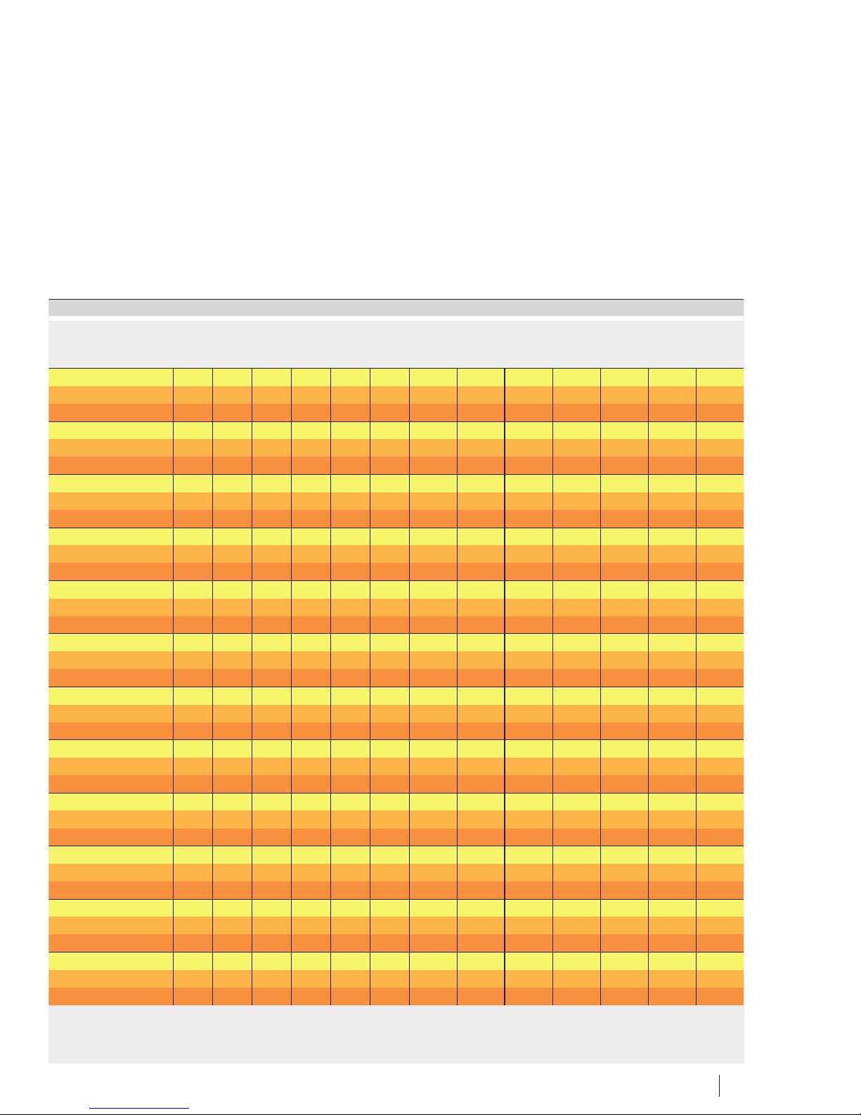
Schaeffler Group Industrial BA 20 33
6,09 6,7 7,37 8,1 8,91 9,81 10,79 11,86 13,05 14,36 15,79 17,37 19,11 21,02
227 249 274 302 332 365 402 442 486 535 588 647 712 783
249 274 302 332 365 402 442 486 535 588 647 712 783 861
4,83 5,32 5,85 6,43 7,08 7,78 8,56 9,42 10,36 11,4 12,54 13,79 15,17 16,69
181 199 219 241 265 292 321 353 388 427 470 517 568 625
199 219 241 265 291 320 353 388 427 469 516 568 625 687
6,5 7,15 7,86 8,65 9,51 10,46 11,51 12,66 13,93 15,32 16,85 18,54 20,39 22,43
258 283 312 343 377 415 457 502 552 608 668 735 809 890
283 311 342 377 414 456 501 551 606 667 734 807 888 977
5,15 5,66 6,23 6,85 7,54 8,29 9,12 10,03 11,03 12,14 13,35 14,69 16,15 17,77
210 232 255 280 308 339 373 410 451 496 546 600 661 727
231 254 279 307 338 372 409 450 495 544 599 659 724 797
6,81 7,49 8,24 9,06 9,97 10,97 12,07 13,27 14,6 16,06 17,66 19,43 21,37 23,51
292 321 353 389 428 470 517 569 626 689 758 833 917 1 008
320 352 387 426 469 515 567 624 686 755 830 913 1 004 1 105
5,3 5,83 6,42 7,06 7,77 8,54 9,4 10,34 11,37 12,51 13,76 15,13 16,65 18,31
230 253 279 307 337 371 408 449 494 543 598 657 723 795
252 277 305 336 369 406 447 491 540 595 654 719 791 870
7,09 7,8 8,58 9,44 10,38 11,42 12,57 13,82 15,2 16,72 18,4 20,24 22,26 24,49
318 349 384 423 465 512 563 619 681 749 824 906 997 1 096
347 382 420 462 508 559 615 677 744 819 901 991 1 090 1 199
5,62 6,18 6,8 7,48 8,23 9,05 9,95 10,95 12,04 13,25 14,57 16,03 17,63 19,39
266 292 322 354 389 428 471 518 570 627 689 758 834 917
290 319 351 386 425 467 514 566 622 684 753 828 911 1 002
5,81 6,39 7,03 7,73 8,5 9,35 10,29 11,31 12,45 13,69 15,06 16,57 18,22 20,04
291 321 353 388 427 469 516 568 625 687 756 831 915 1 006
318 350 385 423 466 512 563 620 682 750 825 907 998 1 098
6,03 6,63 7,29 8,02 8,82 9,7 10,68 11,74 12,92 14,21 15,63 17,19 18,91 20,8
309 340 374 412 453 498 548 603 663 730 803 883 971 1 068
337 371 408 449 494 543 598 657 723 795 875 962 1 059 1 164
6,31 6,94 7,63 8,4 9,24 10,16 11,18 12,29 13,52 14,87 16,36 18 19,8 21,78
367 404 445 489 538 592 651 716 788 867 953 1 048 1 153 1 269
400 440 484 533 586 644 709 780 858 943 1 038 1 141 1 256 1 381
8,38 9,22 10,14 11,15 12,27 13,5 14,84 16,33 17,96 19,76 21,73 23,91 26,3 28,93
506 557 612 674 741 815 897 986 1 085 1 193 1 313 1 444 1 589 1 747
550 605 666 733 806 886 975 1 073 1 180 1 298 1 428 1 570 1 728 1 900
Page 34
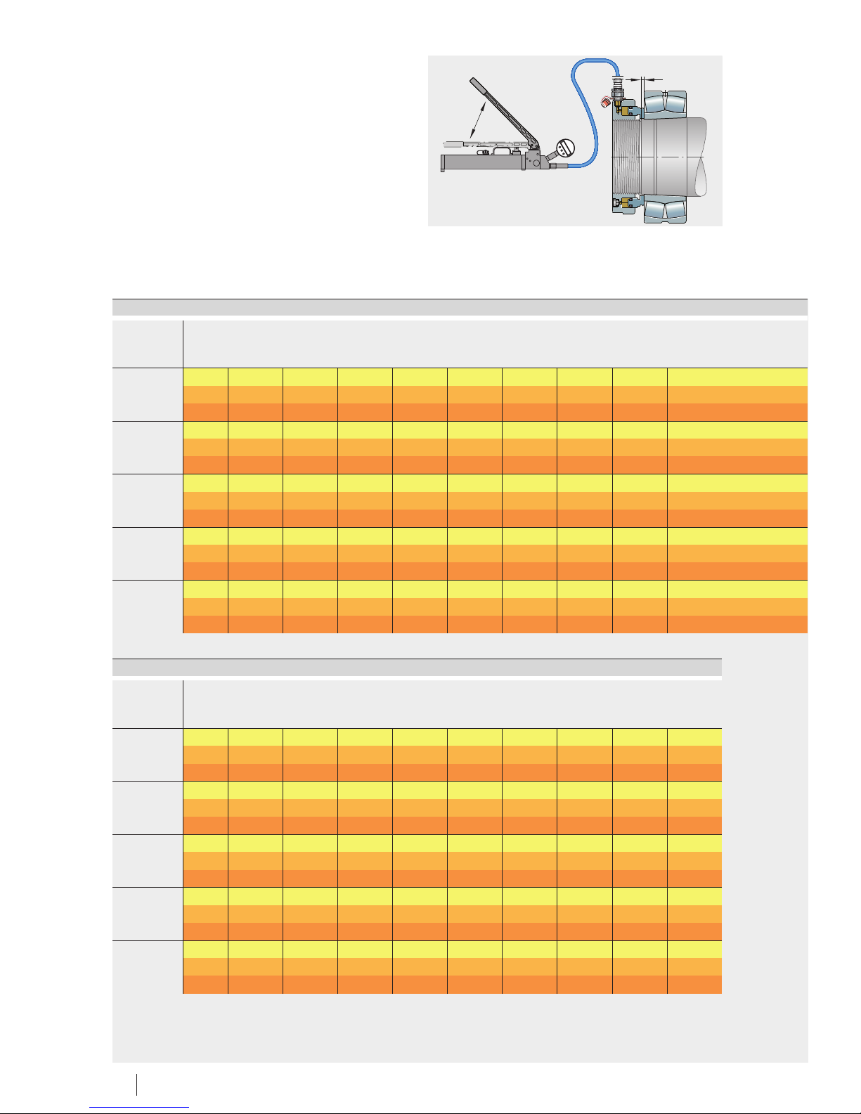
34 BA 20 Schaeffler Group Industrial
Displacement
Number of strokes
s
x , x
12
0000160AD
Value table (continued)
Designation s=Displacement
x1= Number of strokes with hydraulic method
x2= Number of strokes without hydraulic method
HYDNUT
530 s mm 2,67 2,94 3,23 3,55 3,91 4,3 4,73 5,2 5,72
x1– 161 177 195 215 236 260 286 314 346
x2– 175 193 212 233 257 282 311 342 376
550 s mm 2,15 2,37 2,6 2,86 3,15 3,46 3,81 4,19 4,61
x1– 135 148 163 179 197 217 239 262 289
x2– 146 161 177 195 214 236 259 285 313
560 s mm 2,81 3,09 3,4 3,74 4,11 4,53 4,98 5,48 6,02
x1– 185 204 224 247 271 299 328 361 397
x2– 201 221 243 268 295 324 356 392 431
570 s mm 3,16 3,48 3,82 4,21 4,63 5,09 5,6 6,16 6,77
x1– 222 244 269 296 325 358 393 433 476
x2– 240 264 291 320 352 387 426 468 515
580 s mm 2,96 3,26 3,58 3,94 4,33 4,77 5,24 5,77 6,35
x1– 211 232 255 281 309 340 374 411 452
x2– 228 251 276 304 334 367 404 445 489
Value table (continued)
Designation s=Displacement
x1= Number of strokes with hydraulic method
x2= Number of strokes without hydraulic method
HYDNUT
530 s mm 10,87 11,95 13,15 14,46 15,91 17,5 19,25 21,18 23,29
x1– 680 749 823 906 996 1 096 1 206 1 326 1 459
x2– 739 813 894 984 1 082 1 191 1 310 1 441 1 585
550 s mm 14,2 15,62 17,19 18,9 20,79 22,87 25,16 27,68 30,45
x1– 937 1 031 1 134 1 247 1 372 1 509 1 660 1 826 2 009
x2– 1 017 1 119 1 230 1 353 1 489 1 638 1 802 1 982 2 180
560 s mm 11,27 12,4 13,64 15 16,5 18,15 19,97 21,96 24,16
x1– 767 844 929 1 022 1 124 1 236 1 360 1 496 1 645
x2– 832 915 1 006 1 107 1 218 1 340 1 474 1 621 1 783
570 s mm 15,97 17,57 19,33 21,26 23,38 25,72 28,3 31,13 34,24
x1– 1 122 1 235 1 358 1 494 1 643 1 807 1 988 2 187 2 406
x2– 1 215 1 336 1 470 1 617 1 779 1 957 2 152 2 367 2 604
580 s mm 14,96 16,46 18,1 19,91 21,9 24,1 26,5 29,16 32,07
x1– 1 066 1 173 1 290 1 419 1 561 1 717 1 889 2 078 2 286
x2– 1 153 1 268 1 395 1 535 1 688 1 857 2 042 2 247 2 471
Page 35
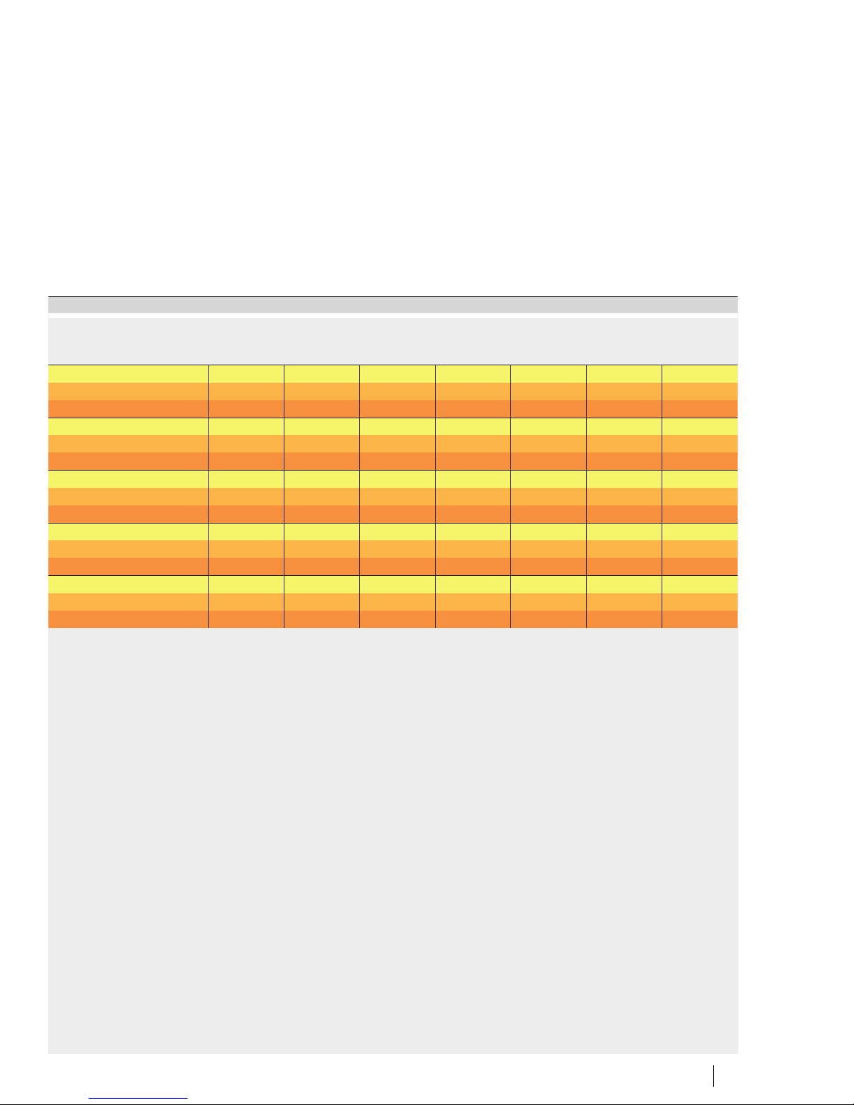
Schaeffler Group Industrial BA 20 35
5,07 5,58 6,13 6,75 7,42 8,16 8,98 9,88
317 349 384 423 465 511 562 619
345 379 417 459 505 555 611 672
6,63 7,29 8,02 8,82 9,7 10,67 11,74 12,91
437 481 529 582 640 704 775 852
474 522 574 631 695 764 840 924
5,26 5,78 6,36 7 7,7 8,47 9,32 10,25
358 394 433 477 524 577 634 698
388 427 470 516 568 625 687 756
7,45 8,2 9,02 9,92 10,91 12 13,2 14,52
524 576 634 697 767 843 928 1 020
567 623 686 754 830 913 1 004 1 104
6,98 7,68 8,45 9,29 10,22 11,24 12,36 13,6
497 547 602 662 728 801 881 969
538 592 651 716 787 866 953 1 048
Page 36
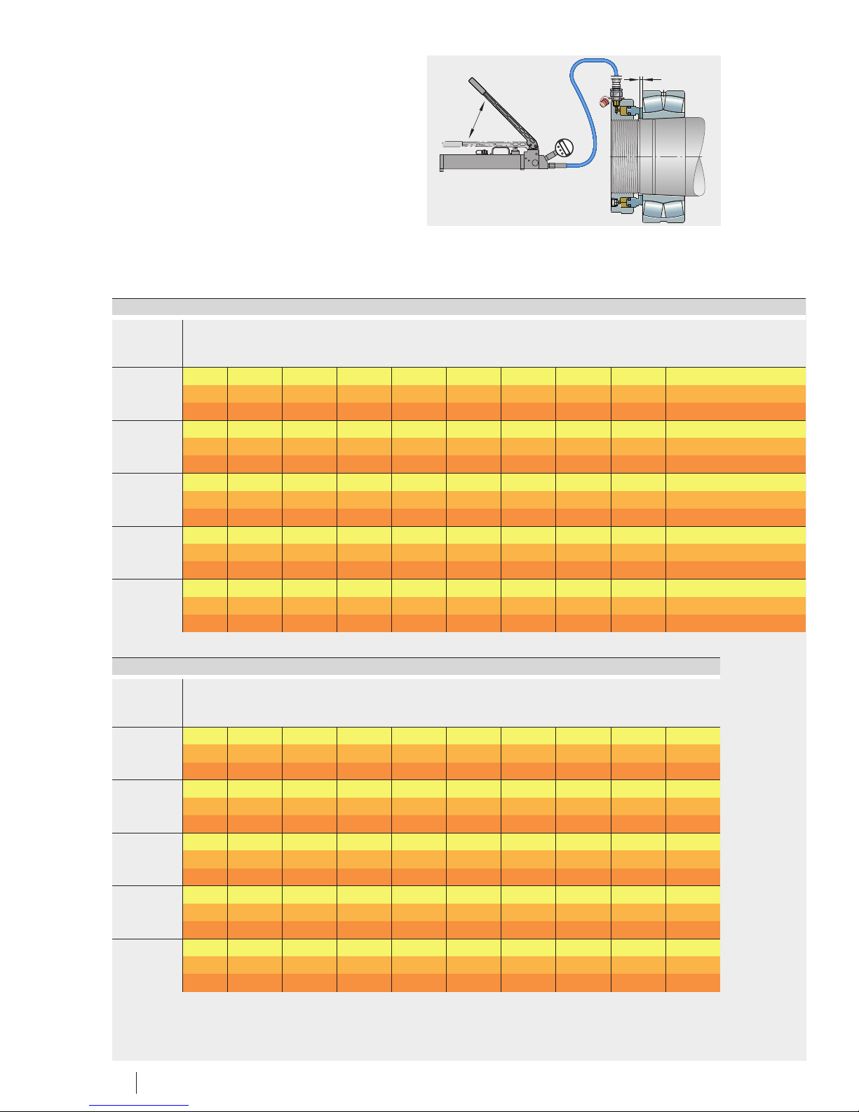
36 BA 20 Schaeffler Group Industrial
Displacement
Number of strokes
s
x , x
12
0000160AD
Value table (continued)
Designation s=Displacement
x1= Number of strokes with hydraulic method
x2= Number of strokes without hydraulic method
HYDNUT
600 s mm 2,41 2,65 2,92 3,21 3,53 3,88 4,27 4,7 5,17
x1– 182 200 220 242 266 293 322 354 390
x2– 196 216 237 261 287 316 348 382 421
625 s mm 3,16 3,48 3,82 4,21 4,63 5,09 5,6 6,16 6,77
x1– 247 272 299 329 362 398 438 481 530
x2– 267 293 323 355 390 429 472 520 572
630 s mm 2,54 2,79 3,07 3,38 3,72 4,09 4,5 4,95 5,44
x1– 205 226 249 273 301 331 364 400 440
x2– 222 244 268 295 324 357 393 432 475
655 s mm 3,34 3,67 4,04 4,45 4,89 5,38 5,92 6,51 7,16
x1– 286 314 345 380 418 460 506 556 612
x2– 308 339 372 410 451 496 545 600 660
670 s mm 2,71 2,98 3,28 3,61 3,97 4,36 4,8 5,28 5,81
x1– 240 264 290 319 351 387 425 468 514
x2– 259 284 313 344 379 416 458 504 554
Value table (continued)
Designation s=Displacement
x1= Number of strokes with hydraulic method
x2= Number of strokes without hydraulic method
HYDNUT
600 s mm 12,18 13,4 14,74 16,21 17,83 19,62 21,58 23,74 26,11
x1– 919 1 010 1 111 1 223 1 345 1 479 1 627 1 790 1 969
x2– 992 1 091 1 200 1 320 1 452 1 598 1 758 1 933 2 127
625 s mm 15,97 17,57 19,33 21,26 23,38 25,72 28,3 31,13 34,24
x1– 1 249 1 373 1 511 1 662 1 828 2 011 2 212 2 433 2 676
x2– 1 348 1 482 1 631 1 794 1 973 2 170 2 387 2 626 2 889
630 s mm 12,84 14,12 15,53 17,09 18,8 20,68 22,74 25,02 27,52
x1– 1 038 1 142 1 257 1 382 1 520 1 672 1 840 2 024 2 226
x2– 1 120 1 232 1 355 1. 491 1 640 1 804 1 984 2 183 2 401
655 s mm 16,88 18,57 20,43 22,47 24,72 27,19 29,91 32,9 36,19
x1– 1 443 1 587 1 746 1 921 2 113 2 324 2 557 2 812 3 094
x2– 1 556 1 711 1 882 2 071 2 278 2 506 2 756 3 032 3 335
670 s mm 13,7 15,07 16,57 18,23 20,05 22,06 24,27 26,69 29,36
x1– 1 213 1 334 1 468 1 615 1 776 1 954 2 149 2 364 2 600
x2– 1 307 1 438 1 581 1 739 1 913 2 105 2 315 2 547 2 801
Page 37
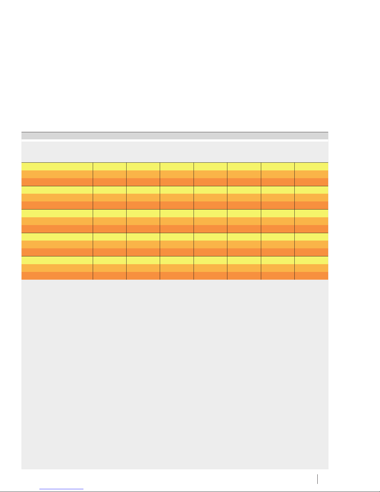
Schaeffler Group Industrial BA 20 37
5,68 6,25 6,88 7,56 8,32 9,15 10,07 11,07
429 471 519 570 627 690 759 835
463 509 560 616 678 745 820 902
7,45 8,2 9,02 9,92 10,91 12 13,2 14,52
582 641 705 775 853 938 1 032 1 135
629 692 761 837 920 1 012 1 114 1 225
5,99 6,59 7,25 7,97 8,77 9,65 10,61 11,67
484 533 586 645 709 780 858 944
523 575 632 696 765 842 926 1 018
7,88 8,66 9,53 10,48 11,53 12,68 13,95 15,35
673 741 815 896 986 1 084 1 193 1 312
726 798 878 966 1 063 1 169 1 286 1 414
6,39 7,03 7,73 8,51 9,36 10,29 11,32 12,45
566 623 685 753 829 911 1 003 1 103
610 671 738 811 893 982 1 080 1 188
Page 38
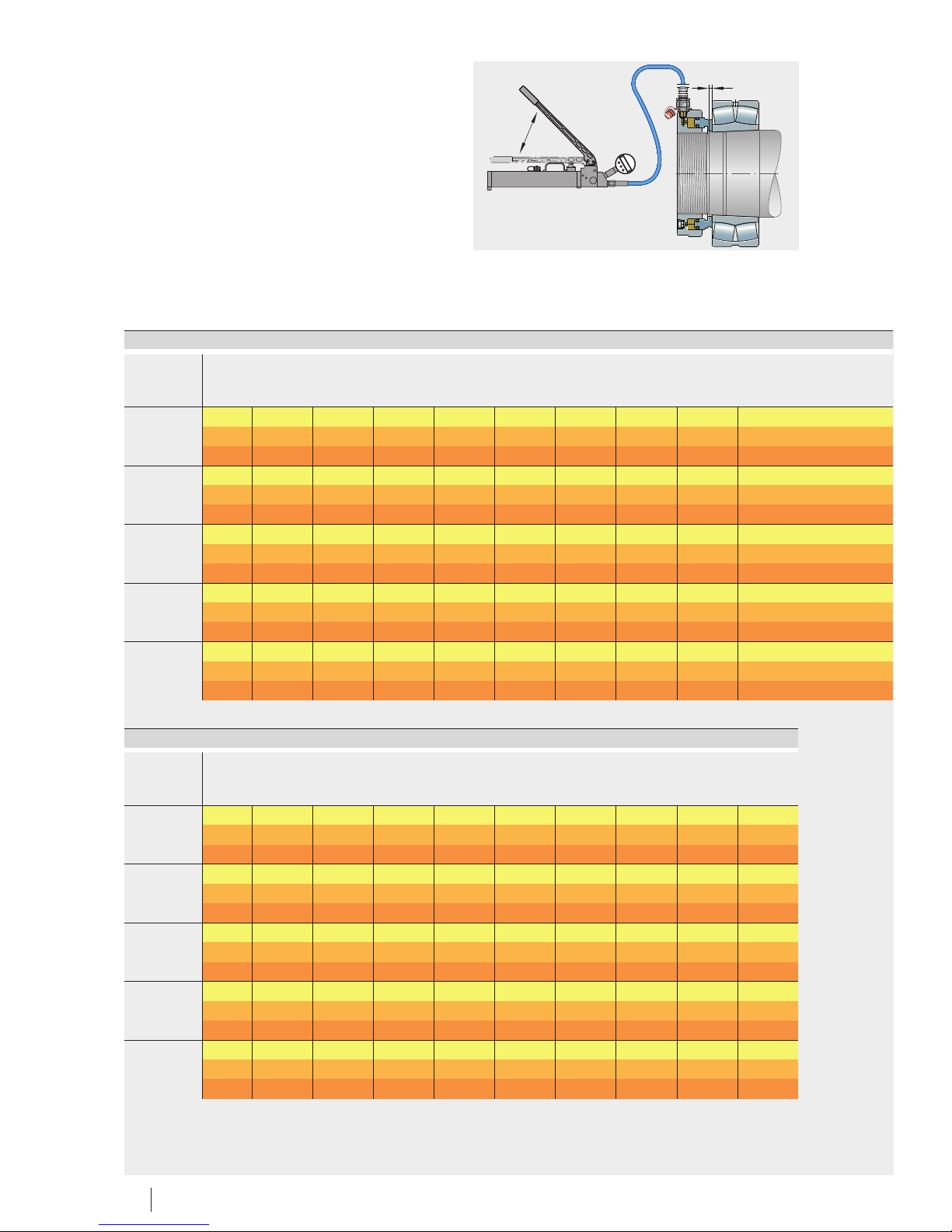
38 BA 20 Schaeffler Group Industrial
Displacement
Number of strokes
s
x , x
12
0000160AD
Value table (continued)
Designation s=Displacement
x1= Number of strokes with hydraulic method
x2= Number of strokes without hydraulic method
HYDNUT
680 s mm 3,71 4,11 4,53 4,98 5,48 6,02 6,63 7,29 8,02
x1– 340 274 412 453 498 548 603 663 730
x2– 367 403 444 488 537 590 649 714 786
695 s mm 3,53 3,88 4,27 4,7 5,17 5,69 6,25 6,88 7,57
x1– 339 373 410 451 496 546 600 661 727
x2– 365 401 441 485 534 587 646 711 782
710 s mm 2,86 3,15 3,46 3,81 4,19 4,61 5,07 5,57 6,13
x1– 279 307 337 371 408 449 494 543 597
x2– 300 330 363 399 439 483 531 584 642
720 s mm 3,94 4,33 4,77 5,24 5,77 6,35 6,98 7,68 8,45
x1– 407 448 493 542 596 656 721 793 873
x2– 438 481 529 582 641 705 775 853 938
740 s mm 3,74 4,11 4,53 4,98 5,48 6,02 6,63 7,29 8,02
x1– 412 453 498 548 603 663 730 803 883
x2– 442 487 535 589 648 713 784 862 948
Value table (continued)
Designation s=Displacement
x1= Number of strokes with hydraulic method
x2= Number of strokes without hydraulic method
HYDNUT
680 s mm 18,9 20,79 22,87 25,16 27,68 30,44 33,49 36,84 40,52
x1– 1 721 1 893 2 082 2 290 2 519 2 771 3 048 3 353 3 688
x2– 1 853 2 038 2 242 2 466 2 713 2 984 3 282 3 610 3 971
695 s mm 17,84 19,63 21,59 23,75 26,12 28,74 31,61 34,77 38,25
x1– 1 713 1 885 2 073 2 280 2 508 2 759 3 035 3 339 3 673
x2– 1 843 2 028 2 231 2 454 2 699 2 969 3 266 3 592 3 952
710 s mm 14,46 15,9 17,49 19,24 21,16 23,28 25,61 28,17 30,99
x1– 1 409 1 549 1 704 1 875 2 062 2 269 2 495 2 745 3 020
x2– 1 515 1 666 1 833 2 016 2 218 2 439 2 683 2 952 3 247
720 s mm 19,91 21,91 24,1 26,51 29,16 32,07 35,28 38,81 42,69
x1– 2 058 2 264 2 490 2 739 3 013 3 315 3 646 4 011 4 412
x2– 2 212 2 433 2 676 2 944 3 238 3 562 3 918 4 310 4 741
740 s mm 18,9 20,79 22,87 25,16 27,68 30,44 33,49 36,84 40,52
x1– 2 082 2 290 2 519 2 771 3 048 3 353 3 689 4 057 4 463
x2– 2 236 2 460 2 706 2 976 3 274 3 601 3 961 4 358 4 793
Page 39
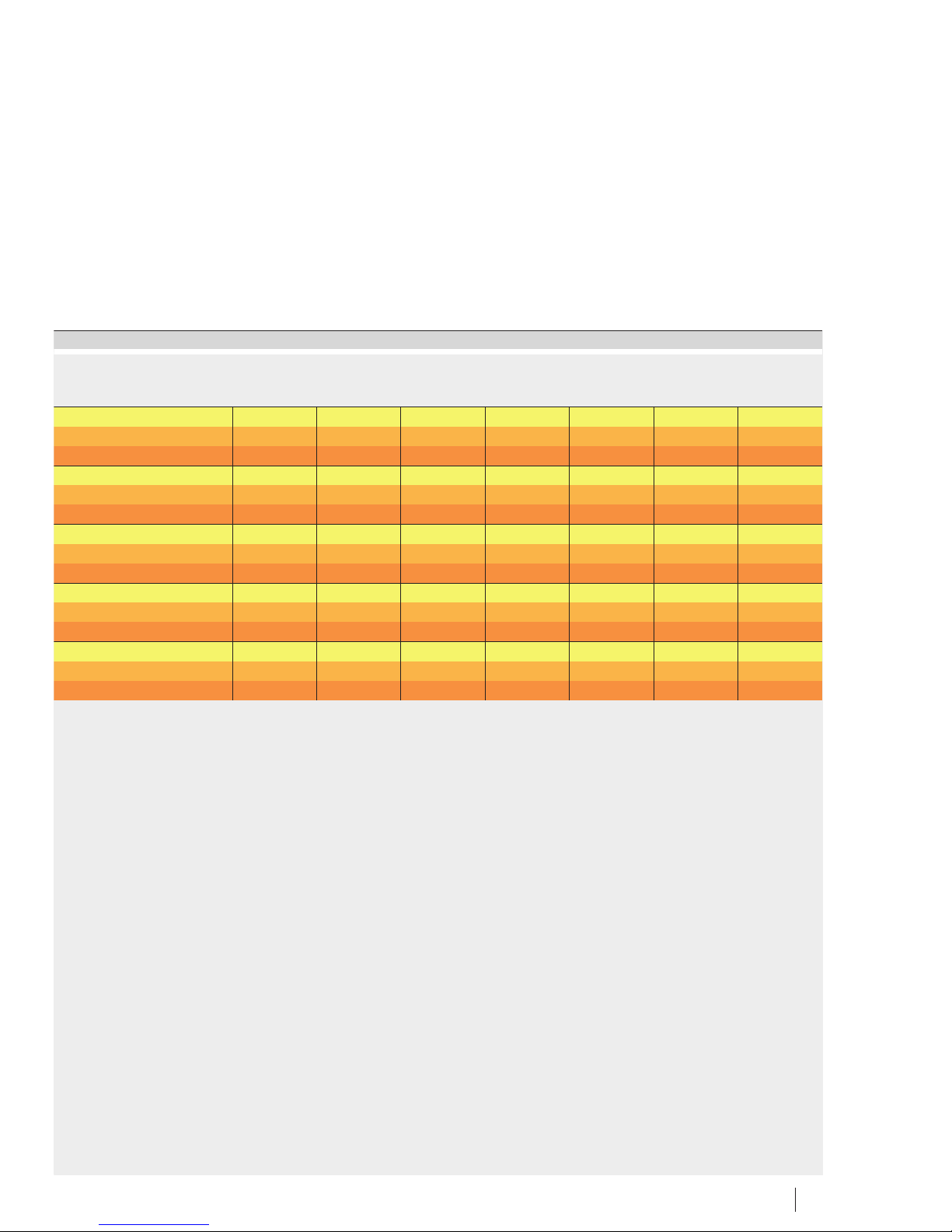
Schaeffler Group Industrial BA 20 39
8,82 9,7 10,67 11,74 12,91 14,2 15,62 17,19
803 883 971 1 068 1 175 1 293 1 422 1 564
864 951 1 046 1 150 1 265 1 392 1 531 1 684
8,32 9,16 10,07 11,08 12,19 13,41 14,75 16,22
799 879 967 1 064 1 170 1 287 1 416 1 558
860 946 1 041 1 145 1 259 1 385 1 524 1 676
6,74 7,42 8,16 8,98 9,87 10,86 11,95 13,14
657 723 795 875 962 1 058 1 164 1 281
707 777 855 941 1 035 1 138 1 252 1 377
9,29 10,22 11,24 12,37 13,6 14,96 16,46 18,1
960 1 056 1 162 1 278 1 406 1 546 1 701 1 871
1 032 1 135 1 248 1 373 1 511 1 662 1 828 2 011
8,82 9,7 10,67 11,74 12,91 14,2 15,62 17,19
971 1 068 1 175 1 293 1 422 1 564 1 721 1 893
1 043 1 147 1 262 1 388 1 527 1 680 1 848 2 033
Page 40
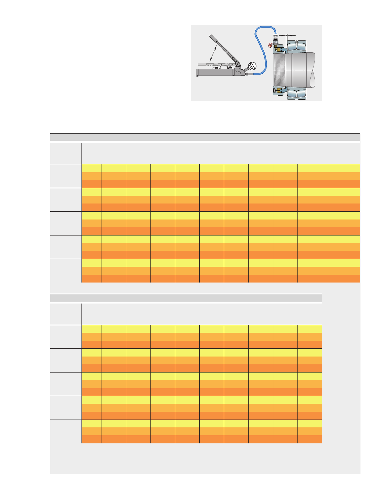
40 BA 20 Schaeffler Group Industrial
Displacement
Number of strokes
s
x , x
12
0000160AD
Value table (continued)
Designation s=Displacement
x1= Number of strokes with hydraulic method
x2= Number of strokes without hydraulic method
HYDNUT
750 s mm 3,82 4,2 4,62 5,08 5,59 6,15 6,77 7,44 8,19
x1– 439 483 532 585 643 708 778 856 942
x2– 472 519 571 628 690 759 835 919 1 011
760 s mm 4,19 4,61 5,07 5,58 6,13 6,75 7,42 8,17 8,98
x1– 487 536 590 649 713 785 863 950 1 045
x2– 523 575 633 696 765 842 926 1.019 1 121
780 s mm 3,94 4,33 4,77 5,24 5,77 6,35 6,98 7,68 8,45
x1– 469 515 567 624 686 755 830 913 1 005
x2– 502 553 608 669 735 809 890 979 1 077
800 s mm 4,01 4,41 4,85 5,34 5,87 6,46 7,1 7,81 8,6
x1– 482 530 583 641 705 776 854 939 1 033
x2– 516 568 625 687 756 831 914 1 006 1 107
830 s mm 4,19 4,61 5,07 5,58 6,13 6,75 7,42 8,17 8,98
x1– 513 565 621 683 752 827 910 1 001 1 101
x2– 550 605 665 732 805 885 974 1 071 1 178
Value table (continued)
Designation s=Displacement
x1= Number of strokes with hydraulic method
x2= Number of strokes without hydraulic method
HYDNUT
750 s mm 19,31 21,24 23,36 25,7 28,27 31,1 34,21 37,63 41,39
x1– 2 221 2 443 2 687 2 956 3 251 3 577 3 934 4 328 4 760
x2– 2.384 2.622 2.884 3.173 3.490 3.839 4.223 4.645 5.109
760 s mm 21,18 23,3 25,63 28,19 31,01 34,11 37,52 41,27 45,4
x1– 2 463 2 709 2 980 3 278 3 606 3 967 4 364 4 800 5 280
x2– 2 642 2 906 3 197 3 517 3 868 4 255 4 681 5 149 5 664
780 s mm 19,91 21,91 21,1 26,51 29,16 32,07 35,28 39,81 42,69
x1– 2 369 2 605 2 866 3 153 3 468 3 815 4 196 4 616 5 077
x2– 2 539 2 793 3 072 3 380 3 718 4 089 4 498 4 948 5 443
800 s mm 20,27 22,3 24,52 26,98 29,68 32,64 35,91 39,5 43,45
x1– 2 435 2 679 2 947 3 242 3 566 3 922 4 314 4 746 5 221
x2– 2 609 2 870 3 157 3 473 3 820 4 202 4 622 5 084 5 593
830 s mm 21,18 23,3 25,63 28,19 31,01 34,11 37,52 41,27 45,4
x1– 2 595 2 855 3 140 3 454 3 800 4 179 4 597 5 057 5 563
x2– 2 778 3 056 3 362 3 698 4 068 4 475 4 922 5 414 5 956
Page 41
Schaeffler Group Industrial BA 20 41
9,01 9,91 10,9 11,99 13,19 14,51 15,96 17,55
1 036 1 140 1 254 1 379 1 517 1 669 1 835 2 019
1 112 1 223 1.345 1.480 1.628 1.791 1.970 2.167
9,88 10,87 11,95 13,15 14,47 18,91 17,5 19,25
1 149 1 264 1 390 1 529 1 682 1 851 2 036 2 239
1 233 1 356 1 491 1 641 1 805 1 985 2 184 2 402
9,29 10,22 11,24 12,37 13,6 14,96 16,46 18,1
1 105 1 215 1 337 1 471 1 618 1 780 1 958 2 153
1 185 1 303 1 433 1 577 1 734 1 908 2 098 2 308
9,46 10,4 11,44 12,59 13,84 15,23 16,75 18,43
1 136 1 250 1 375 1 512 1 663 1 830 2 013 2 214
1 217 1 339 1 473 1 620 1 782 1 960 2 156 2 372
9,88 10,87 11,95 13,15 14,47 15,91 17,5 19,25
1 211 1 332 1 465 1 611 1 773 1 950 2 145 2 359
1 296 1 426 1 568 1 725 1 898 2 087 2 296 2 526
Page 42
42 BA 20 Schaeffler Group Industrial
Displacement
Number of strokes
s
x , x
12
0000160AD
Value table (continued)
Designation s=Displacement
x1= Number of strokes with hydraulic method
x2= Number of strokes without hydraulic method
HYDNUT
850 s mm 4,29 4,72 5,19 5,71 6,28 6,91 7,6 8,36 9,2
x1– 551 606 667 733 807 887 976 1 074 1 181
x2– 590 648 714 785 863 950 1 045 1 149 1 264
880 s mm 4,42 4,86 5,35 5,88 6,47 7,12 7,83 8,61 9,47
x1– 565 621 683 752 827 909 1 000 1 100 1 210
x2– 604 664 730 803 884 972 1 069 1 176 1 294
900 s mm 4,62 5,08 5,59 6,15 6,76 7,44 8,18 9 9,9
x1– 643 707 778 856 941 1 036 1 139 1 253 1 378
x2– 687 755 831 914 1 005 1 106 1 216 1 338 1 472
930 s mm 4,69 5,16 5,67 6,24 6,87 7,55 8,31 9,14 10,05
x1– 673 741 815 896 986 1 084 1 193 1 312 1 443
x2– 718 790 869 956 1 051 1 157 1 272 1 399 1 539
950 s mm 4,89 5,38 5,92 6,51 7,16 7,88 8,66 9,53 10,48
x1– 743 817 898 988 1 087 1 196 1 315 1 447 1 592
x2– 792 870 957 1.053 1.159 1.274 1.402 1.542 1.696
Value table (continued)
Designation s=Displacement
x1= Number of strokes with hydraulic method
x2= Number of strokes without hydraulic method
HYDNUT
850 s mm 21,68 23,85 26,24 28,86 31,75 34,92 38,41 42,26 46,48
x1– 2 785 3 064 3 370 3 707 4 078 4 486 4 934 5 427 5 970
x2– 2 980 3 278 3 606 3 967 4 363 4 799 5 279 5 807 6 388
880 s mm 22,34 24,57 27,03 29,74 32,71 35,98 39,58 43,54 47,89
x1– 2 854 3 140 3 454 3 799 4 179 4 597 5 056 5 562 6 118
x2– 3 051 3 356 3 692 4 061 4 467 4 913 5 405 5 945 6 540
900 s mm 23,35 25,69 28,26 31,08 34,19 37,61 41,37 45,51 50,06
x1– 3 250 3 575 3 933 4 326 4 758 5 234 5 758 6 334 6 967
x2– 3 470 3 817 4 199 4 619 5 081 5 589 6 148 6 763 7 439
930 s mm 23,71 26,08 28,68 31,55 34,71 38,18 42 46,2 50,81
x1– 3 403 3 743 4 117 4 529 4 982 5 480 6 028 6 631 7 294
x2– 3 630 3 993 4 392 4 831 5 314 5 846 6 430 7 074 7 781
950 s mm 24,72 27,19 29,91 32,9 36,19 39,81 43,79 48,17 52,98
x1– 3 753 4 129 4 541 4 996 5 495 6 045 6 649 7 314 8 045
x2– 3 999 4 399 4 839 5 323 5 856 6 441 7 085 7 794 8 573
Page 43
Schaeffler Group Industrial BA 20 43
10,12 11,13 12,24 13,46 14,81 16,29 17,92 19,71
1 299 1 429 1 572 1 729 1 902 2 093 2 302 2 532
1 390 1 529 1 682 1 850 2 035 2 239 2 463 2 709
10,42 11,46 12,61 13,87 15,26 16,78 18,46 20,31
1 332 1 465 1 611 1 772 1 949 2 144 2 359 2 595
1 423 1 566 1 722 1 894 2 084 2 292 2 521 2 774
10,89 11,98 13,18 14,5 15,95 17,54 19,3 21,23
1 516 1 668 1 835 2 018 2 220 2 442 2 686 2 955
1 619 1 781 1 959 2 155 2 370 2 607 2 868 3 155
11,06 12,16 13,38 14,72 16,19 17,81 19,59 21,55
1 587 1 746 1 921 2 113 2 324 2 557 2 812 3 094
1 693 1 863 2 049 2 254 2 479 2 727 3 000 3 300
11,53 12,68 13,95 15,35 16,88 18,57 20,43 22,47
1 751 1 926 2 119 2 330 2 564 2 820 3 102 3 412
1.866 2.052 2 258 2 483 2 732 3 005 3 305 3 636
Page 44
44 BA 20 Schaeffler Group Industrial
Displacement
Number of strokes
s
x , x
12
0000160AD
Value table (continued)
Designation s=Displacement
x1= Number of strokes with hydraulic method
x2= Number of strokes without hydraulic method
HYDNUT
1000 s mm 5,07 5,58 6,13 6,75 7,42 8,17 8,98 9,88 10,87
x1– 841 925 1 017 1 119 1 231 1 354 1 489 1 638 1 802
x2– 895 984 1 083 1 191 1 310 1 441 1 585 1 744 1 918
1060 s mm 5,33 5,86 6,45 7,09 7,8 8,58 9,44 10,39 11,43
x1– 954 1 049 1 154 1 270 1 397 1 536 1 690 1 859 2 045
x2– 1 014 1 116 1 227 1 350 1 485 1 633 1 797 1 976 2 174
1080 s mm 5,81 6,39 7,03 7,73 8,51 9,36 10,29 11,32 12,45
x1– 1 085 1 193 1 313 1 444 1 588 1 747 1 922 2 114 2 326
x2– 1 152 1 268 1 394 1 534 1 687 1 856 2 042 2 246 2 470
1120 s mm 5,62 6,18 6,8 7,48 8,23 9,05 9,96 10,95 12,05
x1– 1 187 1 306 1 436 1 580 1 738 1 911 2 103 2 313 2 544
x2– 1 259 1 385 1 524 1 676 1 844 2 028 2 231 2 454 2 700
1180 s mm 5,91 6,5 7,15 7,87 8,65 9,52 10,47 11,52 12,67
x1– 1 379 1 517 1 669 1 835 2 019 2 221 2 443 2 687 2 956
x2– 1 462 1 608 1 769 1 946 2 140 2 354 2 590 2 849 3 133
Value table (continued)
Designation s=Displacement
x1= Number of strokes with hydraulic method
x2= Number of strokes without hydraulic method
HYDNUT
1000 s mm 25,63 28,19 31,01 34,11 37,52 41,27 45,4 49,94 54,93
x1– 4 249 4 674 5 142 5 656 6 221 6 843 7 528 8 281 9 109
x2– 4 523 4 975 5 473 6 020 6 622 7 284 8 013 8 814 9 695
1060 s mm 26,94 29,63 32,6 35,86 39,44 43,39 47,73 52,5 57,75
x1– 4 821 5 303 5 834 6 417 7 059 7 764 8 541 9 395 10 335
x2– 5 126 5 639 6 203 6 823 7 505 8 256 9 082 9 990 10 989
1080 s mm 29,37 32,3 35,53 39,09 43 47,29 52,02 57,23 62,95
x1– 5 484 6 032 6 635 7 299 8 029 8 831 9 715 10 686 11 755
x2– 5 825 6 407 7 048 7 753 8 528 9 381 10 319 11 351 12 486
1120 s mm 28,41 31,25 34,37 37,81 41,59 45,75 50,32 55,36 60,89
x1– 5 999 6 599 7 259 7 985 8 783 9 661 10 628 11 690 12 859
x2– 6 366 7 002 7 702 8 473 9 320 10 252 11 277 12 405 13 645
1180 s mm 29,87 32,86 36,15 39,76 43,74 48,11 52,21 58,92 64,03
x1– 6 970 7 667 8 434 9 277 10 205 11 225 12 348 13 583 14 941
x2– 7 388 8 127 8 940 9 834 10 817 11 899 13 089 14 398 15 838
Page 45
Schaeffler Group Industrial BA 20 45
11,95 13,15 14,47 15,91 17,5 19,25 21,18 23,3
1 982 2 181 2 399 2 638 2 902 3 193 3 512 3 863
2 110 2 321 2 553 2 808 3 089 3 398 3 738 4 112
12,57 13,82 15,21 16,73 18,4 20,24 22,26 24,49
2 249 2 474 2 721 2 994 3 293 3 622 3 984 4 383
2 391 2 631 2 894 3 183 3 501 3 851 4 237 4 660
13,7 15,07 16,58 18,23 20,06 22,06 24,27 26,7
2 558 2 814 3 095 3 405 3 745 4 120 4 532 4 985
2 717 2 989 3 288 3 617 3 978 4 376 4 814 5 295
13,25 14,58 16,03 17,64 19,4 21,34 23,48 25,82
2 799 3 078 3 386 3 725 4 097 4 507 4 958 5 454
2 970 3 267 3 593 3 952 4 348 4 783 5 261 5 787
13,94 15,33 16,86 18,55 20,4 22,44 24,69 27,16
3 252 3 577 3 934 4 328 4 761 5 237 5 760 6 336
3 447 3 791 4 171 4 588 5 046 5 551 6 106 6 717
Page 46

Schaeffler KG
Georg-Schäfer-Straße 30
97421 Schweinfurt (Germany)
Internet www.fag.de
E-Mail [email protected]
In Germany:
Phone 0180 5003872
Fax 0180 5003873
From other countries:
Phone +49 9721 91-0
Fax +49 9721 91-3435
Every care has been taken to ensure the
correctness of the information contained
in this publication but no liability can be
accepted for any errors or omissions.
We reserve the right to make technical
changes.
© Schaeffler KG · 2009, November
This publication or parts thereof may not
be reproduced without our permission.
BA 20 GB-D
MATNR 036856932-0000 / BA 20 / GB-D / 200911 / pdf only
 Loading...