


Technical Documentation
FAFNIR GmbH • Schnackenburgallee 149 c • 22525 Hamburg • Germany • Tel.: +49 /40 / 39 82 07-0 • Fax: +49 /40 / 390 63 39
TORRIX
The magnetostrictive level sensor
Edition: 2016-09
Version: 16
Art. no.: 207074

I Table of contents
Table of contents
1 Overview................................................................................................. 1
2 Safety instructions ................................................................................. 2
3 Design and function ............................................................................... 3
4 Installation .............................................................................................. 5
4.1 Installation with screw-in unit ............................................................................. 6
4.2 Installation with flange ....................................................................................... 7
4.3 Installation on the bypass ................................................................................... 7
5 Electrical connection .............................................................................. 9
5.1 Wiring diagram TORRIX ...................................................................................... 9
5.2 Wiring diagram TORRIX Ex ................................................................................. 9
5.3 Cable length .................................................................................................... 10
5.4 Wiring .............................................................................................................. 12
6 User configuration ............................................................................... 13
6.1 Measuring span at the level sensor ................................................................... 13
6.2 Current consumption in failure mode ............................................................... 15
7 Maintenance ......................................................................................... 16
7.1 Return shipment............................................................................................... 16
8 Technical data ....................................................................................... 16
8.1 Sensor .............................................................................................................. 16
8.2 Float ................................................................................................................ 18
9 List of figures ........................................................................................ 19
10 Annex .................................................................................................... 20
10.1 EC Declaration of Conformity ........................................................................... 20
10.2 SIL Certificate ................................................................................................... 21
10.3 EC type-examination certificate TÜV 01 ATEX 1772 X ....................................... 24
10.3.1 1st Supplement ................................................................................................ 27

Table of contents II
10.3.2 2nd Supplement ............................................................................................... 28
10.3.3 3rd Supplement ............................................................................................... 29
10.3.4 4th Supplement ............................................................................................... 30
10.4 Instructions ...................................................................................................... 34
© Copyright:
Reproduction and translation is permitted only with the written consent of the FAFNIR GmbH. The FAFNIR
GmbH reserves the right to carry out product alterations without prior notice.

Page 1/36 Overview
1 Overview
The high-precision TORRIX level sensor is designed to provide continuous gauging of
liquid media levels in tanks. The measuring principle used by the sensor exploits the
physical effect of magnetostriction and is largely unaffected by temperature. This method
is particularly ideal where level measurements are required to be extremely accurate, such
as in the chemical industry.
In this documentation, the TORRIX is described as the variant with cable gland. As
another option, the TORRIX with plug connector is available, see:
Technical documentation TORRIX M12, art. no. 350164
The TORRIX supplies a 4 ... 20 mA output signal which is configured using buttons in the
sensor head, or a digital output signal as HART® protocol. Probe lengths are possible from
100 mm to 6 m, as Flex version up to 10 m, as well as versions for different temperature
and pressure ranges.
It also comes in the following versions:
• TORRIX (with screw-in unit, welded or for stepless positioning)
• TORRIX flange (with process connection flange)
• TORRIX Flex (with flexible probe tube)
• TORRIX Bypass (for installation on a bypass with magnetic float)
• TORRIX 90 (with 90° angled sensor head)
• TORRIX 6 (with 6 mm probe tube)
• TORRIX 6B (with 6 mm probe tube and short cable gland)
For the description of communication with the HART® protocol, see:
Technical documentation TORRIX Hart, art. no. 207095
To install the TORRIX Flex version see:
TORRIX Flex Installation Guide multilingual, art. no. 350118
The TORRIX versions can also be supplied as Ex version:
The level sensor TORRIX Ex … with Ex approval (ATEX, IECEx) can be installed in
potentially explosive areas which require equipment protection level Ga (Ex Zone 0),
Ga/Gb (Ex Zone 0/1) or Gb (Ex Zone 1) for electrical equipment.

Safety instructions Page 2/36
2 Safety instructions
The purpose of the TORRIX level sensor is to gauge liquid levels in tanks. The level sensor
must be used exclusively for this purpose. The manufacturer accepts no liability for any
form of damage resulting from improper use!
The level sensor has been developed, manufactured and tested in accordance with the
latest good engineering practices and generally accepted safety standards. Nevertheless,
hazards may arise from its use. For this reason, the following safety information must be
observed:
• Do not change or modify the level sensor or add any equipment without the prior
consent of the manufacturer.
• The installation, operation and maintenance of the level sensor must be carried
out only by expert personnel. Specialised knowledge must be acquired by regular
training.
• Operators, fitters and service technicians must observe all applicable safety regu-
lations. This also applies to any local safety and accident prevention regulations
which are not stated in these operating instructions.
The safety instructions in this manual are marked as follows:
If these safety instructions are not observed, it may result in the risk of
accident or damages to the TORRIX level sensor.
Useful information designed to ensure continued and correct operation of
the TORRIX level sensor or helpful advice to make your work easier.

Page 3/36 Design and function
3 Design and function
The design of the TORRIX level sensor is illustrated in the version with screw-in unit (see
following figure).
Inside sensor head (1) of the level sensor, concealed by cap (2), are the protected terminal
clamps and configuration buttons. The electrical connection is established by an
M16 x 1.5 screwed cable gland (3) or M12 plug-in connection at the top of the sensor
head and by earth connector (4) at the bottom of the sensor head (see chapters
“Installation” and “User configuration”).
Probe tube (5) features a screw-in unit (6) (cutting ring fitting or ferrule fitting) for height
adjustment capability or a flange (not shown) for fixed installation. Float (7) is the key
component for continuous gauging of the product filling level or boundary layer and is
held on the probe tube by a guard ring (8).
The TORRIX Bypass version is supplied without a process connection and a float.
Figure 1: TORRIX level sensor
1
4
5
6 7 2 3 8

Design and function Page 4/36
The measuring principle illustrated in the following figure exploits the physical effect of
magnetostriction and is largely unaffected by temperature. The probe tube contains a
tensioned wire (1) made of magnetostrictive material. The sensor electronics transmit
current pulses (2) through the wire, which generate a circular magnetic field (3). A
magnet (4) contained in the float acts as the filling level sensor. Its magnetic field applies
an axial magnetic field to the wire. The superposition of the two magnetic fields produces
a torsional wave (5) at the float position, which then propagates along the wire in both
directions. One wave propagates directly to the sensor head, the other propagates down
to the bottom of the probe tube and is reflected. The time between the current pulse
being transmitted and the wave arriving at the sensor head is measured. From these
propagation times, it is possible to determine the current position of the float.
Figure 2: Operating principle of the TORRIX level sensor
2
3
5
4
1
5

Page 5/36 Installation
4 Installation
When installing and maintaining the level sensor in potentially explosive
areas, the national rules must be observed (Explosion Protection Regulations,
Industrial Health and Safety Regulations, Equipment Safety Regulations and
specific conditions of the EC-type examination certificates). The generally
accepted rules of engineering and these operating instructions must be observed.
All applicable local safety and accident prevention regulations not included
in these operating instructions must also be observed.
This section describes how to install the level sensor depending on the type (see the
following figure).
TORRIX screw-in unit TORRIX flange TORRIX Bypass
Figure 3: TORRIX versions
Probe length
Sensor head
Sensor head
Screew-in
unit
Probe tube
ø 12
Probe tube
ø 12
Float
Guard ring
Guard ring
Float
Flange
Neck tube
Probe length
Installation length
112
∅ 50
∅ 50
∅
50
112
116
88

Installation Page 6/36
During installation, take great care not to bend the probe tube, and
protect the float from shock and impact loads.
Installing a level sensor in areas exposed to a powerful external magnetic
field is not permitted because this could impair gauging.
The level sensor can also be fitted into the tank from underneath.
If the float is removed during installation, it must be slid back onto the
probe tube afterwards with the “TOP” marking oriented towards the sensor head end, to enable correct measurements to be made.
4.1 Installation with screw-in unit
Figure 4: Installation with screw-in unit
Removal of the float is necessary only if the float does not fit through the
installation opening in the tank. Otherwise, please proceed directly to steps
3, 6 and, if applicable, 7.
Insert the level sensor into the tank (see Figure 4):
(1) Loosen both set screws, remove guard ring (1) and remove float (2) from probe
tube (3).
(2) If necessary, slot screw-in unit (4) onto the probe tube.
(3) Insert the level sensor into the tank, provide screw-in unit thread (4) with a
suitable sealing material, screw it in and tighten.
(4) Slide float (2) back onto probe tube (3).
For correct gauging, the float must be slid onto the probe tube with the
“TOP” marking oriented towards the sensor head end, to enable correct
measurements to be made.
(5) Refit guard ring (1) on the tube, align the set screws with the groove and tighten.
1 2 3 4 5

Page 7/36 Installation
(6) Adjust the height of the process connection and fix the union nut (5) by hand
finger-tight.
(7) Fix the union nut (5) with a wrench by a 1¼ clockwise turn (see following figure).
Figure 5: Compression fitting fixing
4.2 Installation with flange
The probe tube is permanently welded to the flange, which means that the installation
length cannot be altered.
Secure the flange using the flange screws.
If the float does not fit through the installation opening, see installation instructions
chapter 4.1.
4.3 Installation on the bypass
The level sensor is mounted at the side of the bypass tube using suitable non-magnetic
fasteners.
To ensure reliable gauging, the probe tube must be fitted with no
deformation on the outside.
The distance between the probe and bypass tubes must be as small as possible.
Only floats approved by FAFNIR can be used.
5

Installation Page 8/36
Figure 6: Installation on the bypass
montiert (unverformt)
Magnetposition
min.
max.
Magnetposition
Magnet
position
Bypassr
ohr
T
ORRIX Bypass
S
ondenrohr spannungsfrei
Bypass-Schwimmer
70 mi
n.
Messberei
ch
Schwimmermitte: max. Abst
and
abhängig vom Bypass-Schwimmer
Abstand Sondenrohr zu
50 m
in.
S
ondenl
äng
e
A
A
SCHNITT A-A
Abstandshalter
Sondenbefestigung
(unmagneti
sch
)
Distance between probe tube
and float centre: max. distance
depends on the bypass float
Bypass float
Probe tube tension-
free
mounted (undeformed)
Bypass tube
Magnet position
Spacer
Probe fixture
(non-magnetic)
Probe length
max.
Magnet position
min.
Magnet position
Measuring range
Section A-A
TORRIX Bypass

Page 9/36 Electrical connection
5 Electrical connection
5.1 Wiring diagram TORRIX
The level sensor without Ex approval is installed in accordance with the following wiring
diagram:
Figure 7: Wiring diagram TORRIX
Power supply: U
max
= 30 V DC
Minimum supply voltage: U
min
= 8 V
Total resistance (including cable resistance and load): ΣR = (U - U
min
) / 0,0215 A
To connect the cable, see chapter 5.4
5.2 Wiring diagram TORRIX Ex
The level sensor with Ex approval is installed in accordance with the following wiring
diagram:
Figure 8: Wiring diagram for TORRIX in a potentially explosive atmosphere
Power supply: U
max
= 30 V DC
Minimum supply voltage: U
min
= 8 V
Total resistance (including cable resistance and load): ΣR = (U - U
min
) / 0,0215 A
+
+
_
Y
I
R1
R2
R3
U
TORRIX
Spannungsquelle
Leitungswiderstände
Bürde
U = 30 V
max
U = 8 V
min
Y
I
+
-
R1
R2
TORRIX (Ex-Ausführung)
Leitungswiderstände
Trennverstärker (Beispiel)
Hilfsenergie
4...20 mA
+
-
4...20 mA
8...30 V
Power supply
Line resistance
Load
Isolation amplifier
(example)
Line resistance
Power supply
(Ex version)

Electrical connection Page 10/36
The intrinsically safe version of the TORRIX Ex level sensor, when installed in
a potentially explosive atmosphere, is permitted to be connected only to
isolation amplifiers that have been certified by a recognised inspection authority and offer electrical outputs that meet the following conditions:
U0 ≤ 30 V
I0 ≤ 200 mA
P0 ≤ 1 W
Further data can be found in the EC type-examination certificate (refer to the Appendix).
If the level sensor is to be used in a potentially explosive atmosphere, always
make sure that the permissible capacitance and inductance of the isolation
amplifier are not exceeded (refer to the electrical data in the EC typeexamination certificate).
Used in an explosion-proof application, the connecting cable to the isolation amplifier
must be marked, preferably as a blue cable for intrinsically safe electric circuits.
To connect the cable, see chapter 5.4
5.3 Cable length
The maximum cable length depends on the total resistance (see Chap. 5.1 / 5.2),
composed of the line resistances and the load of connected devices.
The cable (length and cross-section) must be chosen so that the supply
voltage will not fall below the sensor-specific minimum voltage (8 V) in the
event of a maximum current consumption (21.5 mA) .
If the level sensor is to be used in a potentially explosive atmosphere, always
make sure that the permissible capacitance and inductance of the associated equipment are not exceeded (refer to the electrical data in the EC typeexamination certificate).
Because of the voltage drop of 12 V the connection housing HPH Ex d and
the safety barrier SB1 can be used with TORRIX only at a supply voltage
higher than 20 volts.

Page 11/36 Electrical connection
The following table shows the maximum total resistances at different supply voltages, and
cable resistances at various cross-sections:
Supply
voltage [V]
Max. total
resistance [Ω]
Cable cross-
section
[mm²]
Cable resistance
per m copper
-
cable [Ω/m]
For connection
housing HPH Ex d
suitable (yes/no)
12 (-5%)
158
0.5
0.0356
no
1.0
0.0178
no
1.5
0.0119
no
24 (-5%)
688
0.5
0.0356
yes
1.0
0.0178
yes
1.5
0.0119
yes
The max. cable length is calculated as follows:
L = (((U – U
min
) / I
max
) – RB) / RQ
L = Cable length [m]
U = Supply voltage [V] (with negative tolerance value -5%)
U
min
= Minimum supply voltage [V] = 8 V
I
max
= Maximum power consumption [A] = 0.0215 A
RB = Load
RQ = cable resistance copper cable per m [Ω/m] for cable cross-section Q [mm²]
Example:
Supply voltage: 12 V (± 5%)
Supply voltage U = 11.4 V (12 V - 5%)
Minimum supply voltage U
min
= 8 V
Highest power consumption I
max
= 0.0215 A
Load RB = 86.8 Ω
Cable resistance RQ = 0.0356 Ω/m at cable cross-section Q = 0.5 mm²
L = (((11,4 – 8) / 0,0215) - 86,8) / 0,0356 = 2000 m
Thus a cable with forward and return line (2-wire) can be up to 1000 m long.

Electrical connection Page 12/36
5.4 Wiring
The wiring is not required for the variant TORRIX with M12 connector.
Assignment of the M12 connector: Pin 1 = brown (+), Pin 3 = blue (-)
For the wiring of the level sensor, proceed as follows:
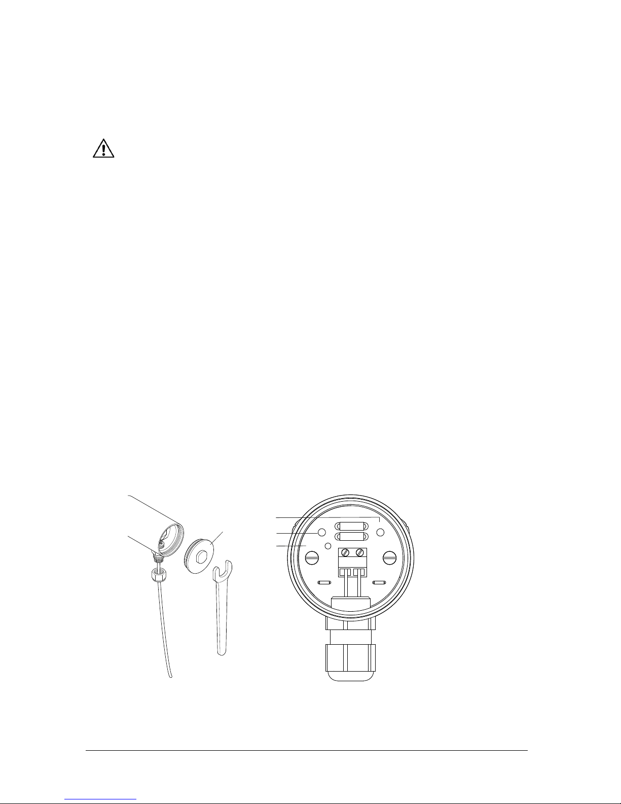
(1) Unscrew sensor head cap (1) using an open-ended spanner.
(2) Loosen union nut (2) of screwed cable gland (3).
Figure 9: Wiring
Figure 10: Removable screw terminal
(3) Feed the two-core cable (4) into the union nut (2) and tighten the nut.
The external diameter must be 5 to 10 mm.
(4) Remove screw terminal (5).
(5) Connect the two-core cable to the (+) and (–) marked pols of the screw terminal (5).
(6) Plug the screw terminal (5) back on. The cable must have no traction.
(7) Configuration of reference points if necessary (see chapter 6.1 )
(8) Screw sensor head cap (1) back on.
1
3
2
4
C
al/Er
r
+
4 mA 20 mA
–
3
2
4
5
5
Page 13/36 User configuration
The earth connector on the underside of the sensor head can be used for earthing or
equipotential bonding.
Protect the sensor head against the ingress of water. An external cable
diameter of 5 to 10 mm ensures reliable sealing of the cable entry. Make
sure that the cable gland is screwed tight, and close the sensor head cap
firmly.
6 User configuration
Versions that support the HART® protocol enable the adjustments carried
out remotely without the sensor head having to be opened.
6.1 Measuring span at the level sensor
To enable configuration of the 4 mA and 20 mA points at the TORRIX level sensor, two
buttons and an LED (light emitting diode) are provided near the terminals inside the
sensor head.
By default, the level sensor is set to maximum measuring span with 4 mA at the sensor
base and 20 mA at the sensor head. The measuring span is configurable for adaptation to
the tank concerned. However, a minimum clearance of 10 mm must be observed.
If this minimum clearance is not observed, the display direction of the level sensor will be
reversed automatically (ullage measurement).
Through configuration, it is also possible to have the measured value output inverted: e.g.
the level sensor can be set to maximum measuring span with 4 mA at the sensor head
and 20 mA at the sensor base.
Figure 11: Adjustment of the measuring span
1
+
4 mA
20 mA
–
3
4
Cal/Err
2

User configuration Page 14/36
(1) Unscrew sensor head cap (1) using an open-ended spanner.
(2) Press and hold 4 mA button (2) or 20 mA button (3) for at least 3 seconds. The
green LED begins to flash.
(3) The level sensor is now in configuration mode. The current consumption of the
level sensor is 12 mA. If no button is pressed again, the level sensor remains in
configuration mode for 20 seconds before reverting to measuring mode and discarding any changes. In configuration mode, the 4 mA or 20 mA reference point,
or both, can be modified in any order.
To define a reference point:
(4) Move the float to the desired reference point and
− briefly press (0.1 to 2 seconds) “4 mA” button (2) to define a current consump-
tion of 4 mA at this position
− briefly press (0.1 to 2 seconds) “20 mA” button (3) to define a current consump-
tion of 20 mA at this position
When the “4 mA” button is pressed, the LED goes out for 5 seconds. When the
“20 mA” button is pressed, the LED lights up permanently for 5 seconds.
The sensor then remains in configuration mode for a further 15 seconds before storing
the change and reverting to measuring mode.
The new measuring range configuration is not stored until the level sensor
reverts automatically from adjustment mode to configuration mode and the
LED goes out. The new configuration is retained even if the level sensor is
subsequently disconnected from the power supply.
For “dry” settings to be possible in the case of bypass sensors, a magnetic
system with spacer bracket will need to be obtained from the manufacturer
of the bypass. Configuration can then be carried out even with the sensor
removed.

Page 15/36 User configuration
6.2 Current consumption in failure mode
If a malfunction is preventing the level sensor from recording a plausible float position,
i.e. the measured level is incorrect, the sensor will enter failure mode after a short time.
Failure mode signalling conforms to the NAMUR NE43 recommendation. The failure
current is set by default to 21.5 mA but this value can also be set to 3.6 mA.
To configure current consumption in failure mode (see Figure 11)
(1) Unscrew sensor head cap (1) using an open-ended spanner.
(2) Press and hold both the “4 mA” (2) and “20 mA” (3) simultaneously for at least
3 seconds.
Green LED (4) “Cal/Err” flashes rapidly.
The current consumption of the level sensor is 16 mA. After 5 seconds, the LED
stops flashing and indicates the selected failure current consumption for 2.5 seconds. If the LED is on permanently, I
failure
is 21.5 mA; if the LED turns off, I
failure
is
3.6 mA.
If no button is pressed then, the level sensor remains in failure mode for a further
2.5 seconds before reverting to measuring mode and discarding the change.
(3) To set a current consumption
− of 3.6 mA during the dwell time (10 sec) in the fault mode, briefly press the
"4 mA" (2) button (0.1 … 2 seconds).
− of 21.5 mA during the dwell time (10 sec) in the fault mode, briefly press the
"20 mA" (3) button (0.1 … 2 seconds).
The new measuring range configuration is not stored until the level sensor
reverts automatically from adjustment mode to configuration mode and the
LED goes out. The new configuration is retained even if the level sensor is
subsequently disconnected from the power supply.
(4) Screw sensor head cap (1) back on.
If, during operation, the level sensor detects that the level cannot be output
correctly due to an insufficient supply voltage, it enters failure mode and
sets current consumption to 3.6 mA (regardless of any failure current settings).

Maintenance Page 16/36
7 Maintenance
7.1 Return shipment
Before returning any FAFNIR equipment the returned goods authorization by the FAFNIR
customer care is required. Please contact your account manager or the customer care to
get the instructions for the return of goods.
The return of FAFNIR equipment is possible only with authorization by the
FAFNIR customer care.
8 Technical data
8.1 Sensor
Electrical connection
Two-line terminal
4 to 20 mA (3.8 ... 20.5 mA) current consumption for level display
21.5 mA (3.6 mA) current consumption in failure mode
Supply voltage:
TORRIX
TORRIX EX
8 ... 30 V DC
8 ... 30 V DC
Process connection Screw-in unit with possibility of variable height adjustment
Standard G ½ (cutting ring coupling)
Flange on request
For material, see probe tube
Bypass assembly
Sensor head Height 112 mm, Bypass version 116 mm
IP68 (in accordance with TÜV NORD test report 13 993 1204 83 of
02.09.2013)
Material: stainless steel
Cable diameter 5 to 10 mm
Temperature -40 ... +85 °C
Probe tube Length 200 to 6,000 mm (to order)
Length TORRIX Flex 1.5 m ... 10 m
Diameter 12 mm (other diameters on request)
Material: 1.4571 standard
(Hastelloy, or other materials on request)
Measuring range freely configurable (> 10 mm)
Normal temperature (NT) -40 °C … +125 °C
High temperature (HT) -40 °C … +250 °C
Ultra high temperature (HHT) -40 °C … +450 °C
Low temperature (LT) -65 °C … +125 °C
Communication HART® protocol (available)

Page 17/36 Technical data
Accuracy
NT/LT digital component
Linearity better than ±0.2 mm or ±0.01 %,
better than ±0.001 % per K
Repetition accuracy better than 0.05 mm
Resolution better than 10 µm
Accuracy
HT/HHT digital component
Linearity better than ±0.5 mm or ±0.025 %,
better than ±0.01 % per K
Repetition accuracy better than 0.1 mm
Resolution better than 50 µm
Accuracy
Bypass digital component
Linearity better than ±0.5 mm or ±0.025 %,
better than ±0.001 % per K
Repetition accuracy better than 0.05 mm
Resolution better than 10 µm
Accuracy
HT/HHT Bypass digital
component
Linearity better than ±2 mm or ±0.1 %,
better than ±0.01 % per K
Repetition accuracy better than 0.5 mm
Resolution better than 50 µm
Accuracy
Analogue component
Linearity better than ±0.01 %
Temperature drift better than ±0.01 % per K
Resolution better than 0.5 µA (16 bit)

Technical data Page 18/36
8.2 Float
The float is a key component of the level sensor that must be matched to the medium in
respect of density, pressure resistance and material durability.
The following floats are exchangeable and are available to order separately. Other float
types and materials are available on request.
The density and magnet position of floats of the same type may vary
slightly, in which case readjustment may be required.
All floats are also suitable for use at a pressure of -1 bar (vacuum).
Excerpt from available float range:
min. medium
density [g/cm³]
Material
max. operating pressure
[bar] at 20 °C *)
Shape
[mm]
0.5
0.6
0.7
0.7
0.7
0.85
0.95
Titanium
1.4571 / 316 Ti
1.4571 / 316 Ti
C276
1.4571 / 316 Ti
1.4571 / 316 Ti
1.4571 / 316 Ti
20
20
16
10
40
20
50
Ball ø 50
Ball ø 52
Cylinder ø 53
Cylinder ø 46
Ball ø 52
Ball ø 43
Ball ø 43
*) above 50 °C the maximum operating pressure decreases
Pressure resistance is guaranteed for undamaged floats only. Even the most
minor and invisible dents, which can occur if, for example, the float is
dropped from a bench onto a stone floor, are sufficient to cause a significant deterioration in pressure resistance.

Page 19/36 List of figures
9 List of figures
Figure 1: TORRIX level sensor .......................................................................................... 3
Figure 2: Operating principle of the TORRIX level sensor .................................................. 4
Figure 3: TORRIX versions ................................................................................................ 5
Figure 4: Installation with screw-in unit ........................................................................... 6
Figure 5: Compression fitting fixing ................................................................................. 7
Figure 6: Installation on the bypass .................................................................................. 8
Figure 7: Wiring diagram TORRIX .................................................................................... 9
Figure 8: Wiring diagram for TORRIX in a potentially explosive atmosphere ...................... 9
Figure 9: Wiring ............................................................................................................ 12
Figure 10: Removable screw terminal ............................................................................ 12
Figure 11: Adjustment of the measuring span ............................................................... 13


Page 1/3
FAFNIR GmbH Bahrenfelder Str. 19 22765 Hamburg Telephone: +49 / (0) 40 / 39 82 07-0 Fax: +49 / (0) 40 / 390 63 39
IIIInstructions
nstructionsnstructions
nstructions
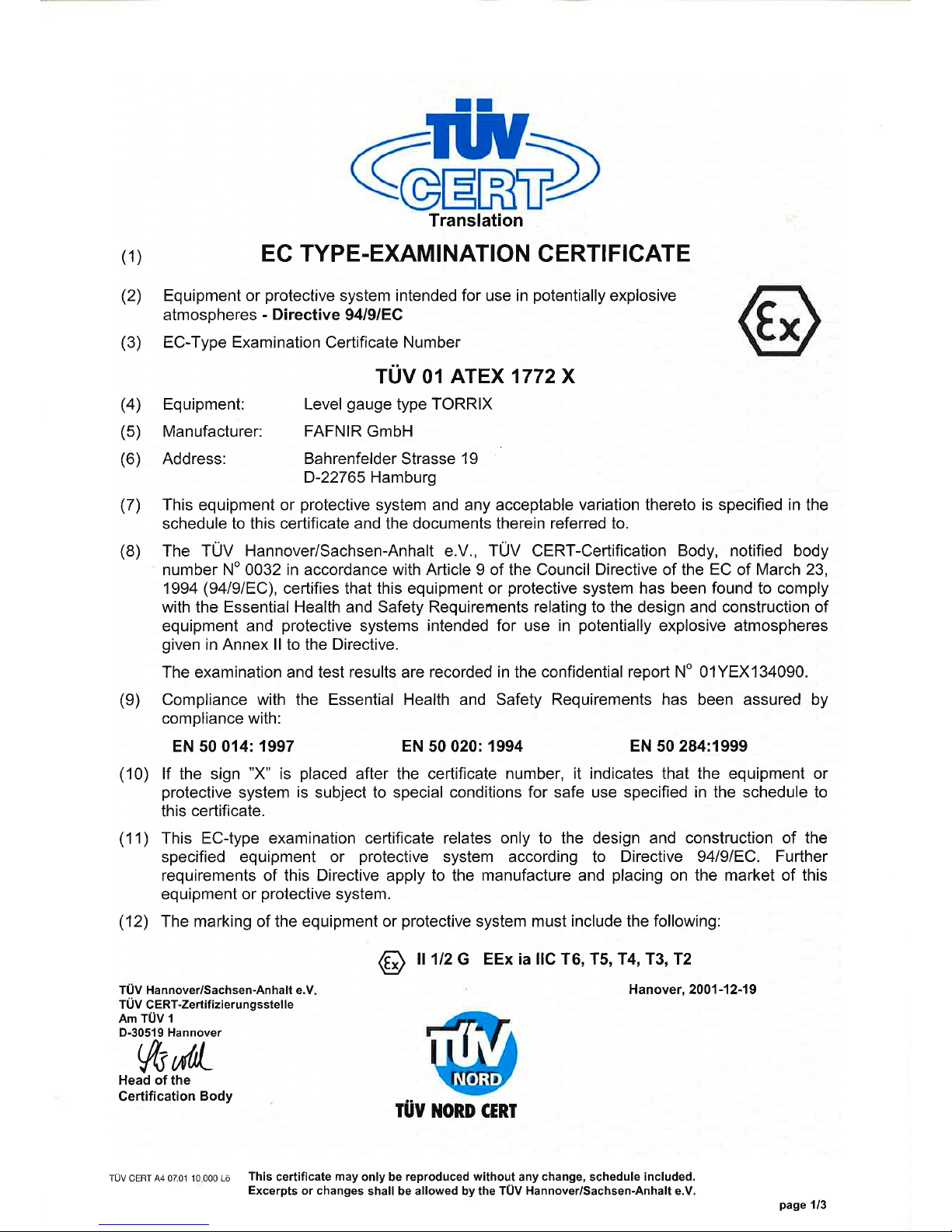
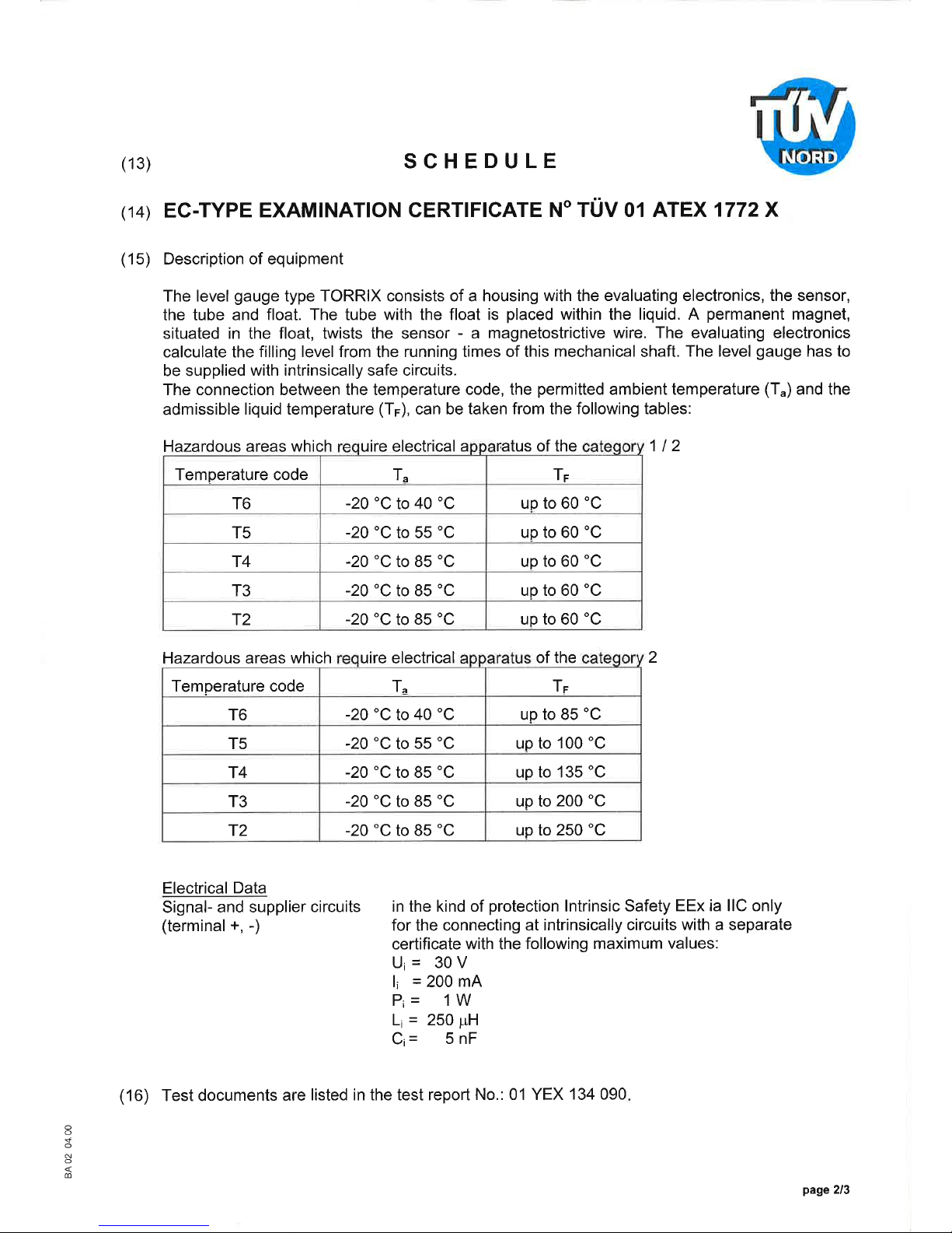
TÜV 01 ATEX 1772 X
Level Sensor
Level SensorLevel Sensor
Level Sensor TORRIX
TORRIXTORRIX
TORRIX Ex
ExEx
Ex ………… Edition: 07.2011
IIII Range of application
Range of applicationRange of application
Range of application
The intrinsically safe equipment TORRIX Ex ... is used for the continuous measurement of liquid levels. The
magnetostrictive measurement system detects the filling level by means of a float and the water level in
case of a second float. These move up and down the probe tube.
II
IIII
II Standards
StandardsStandards
Standards
See EC-type examination certificate including supplements.
IIIIII
IIII
II Instructions for safe
Instructions for safeInstructions for safe
Instructions for safe …………
IIIIII
IIII
II....aaaa ………… use
useuse
use
The sensor is designed as intrinsically safe apparatus and is approved for use in potentially explosive areas.
The level sensor can be installed in Ex Zone 0 and is suitable for all gas groups (IIA, IIB and IIC).
A plastic float for LPG tanks can be used, as inside LPG tanks no explosive atmosphere is present.
The approval applies for all types TORRIX Ex ...
III.b
III.bIII.b
III.b …
… …
… assembling and dismantling
assembling and dismantlingassembling and dismantling
assembling and dismantling
TORRIX Ex … (without process connection)
If the level sensor is supplied without process connection, the installer is responsible for compliance
with the Ex requirements.
With a riser installation the plastic centring aid is plugged onto the sensor head. Then let the sensor slide in the riser until it stands firmly on the bottom.
TORRIX Ex E …
Seal the threads of the screw in unit with a suitable sealing material, screw it into the existing
socket and tighten it.
In the case of installation with a cutting ring coupling, it is no longer possible to alter the position
of the level sensor after the union nut has been tightened.
TORRIX Ex F … and TORRIX Ex TAG-…
The probe tube is permanently fixed to the flange, which means that the installation length cannot
be altered. Seal the flange with a suitable sealing and fix it with flange bolts or nuts.
TORRIX Ex … Flex …
This type can be manufactured with different probe feet, which are used to stabilize the probe. A
foot can be a magnetic base. The magnet is then encapsulated in an electrically conductive plastic
and may therefore be used in explosion hazardous areas.
General remark (see also EN 60079-26, clause 4.6):
Attention must be paid, if the level sensor is built into the boundary wall between Zone 0 and Zone 1,
that a protection class of at least IP67 is achieved after installation.

Page 2/3
FAFNIR GmbH Bahrenfelder Str. 19 22765 Hamburg Telephone: +49 / (0) 40 / 39 82 07-0 Fax: +49 / (0) 40 / 390 63 39
IIIIII
IIII
II.c
.c.c
.c ………… Installation
InstallationInstallation
Installation
All wiring operations must solely be carried out with the power disconnected. The special regulations
including EN 60079-14 and local installation regulations must be observed.
TORRIX Ex … (4 … 20 mA) and TORRIX Ex … HART …
The level sensor has a two-pole electrical connector. The level signal is included in the supply current. In addition, using TORRIX Ex ... HART ... it can be communicated with the sensor via HART
protocol.
TORRIX Ex … SC …
The level sensor has a four-pole electrical connector. The level signal is transmitted in a digital, serial communication.
TORRIX Ex TAG-…
The level sensor has a two-pole electrical connector. The level signal is transmitted in accordance
with the standard EN 14116.
Via the connector, the sensor is powered and the level signal is forwarded simultaneously to the parent
measurement converter. The wiring from the sensor to the measurement converter shall be carried out
using a two- or four-wire cable (preferably blue). The terminals on the sensor must be connected to the
same terminals on the transducer.
For integration into the equipotential bonding a PA terminal is present at the sensor head.
III.
III.III.
III.dddd …
… …
… putting into service
putting into serviceputting into service
putting into service
Before putting into service, all devices must be checked of right connection and fitting. The power supply,
as well of connected devices, must be checked.
III.
III.III.
III.eeee …
… …
… mmmmaintenance, overhaul and repair
aintenance, overhaul and repairaintenance, overhaul and repair
aintenance, overhaul and repair
Generally the device is maintenance-free. In case of a defect it must be send back to FAFNIR or one of his
representations.
IIIIVVVV Marking
MarkingMarking
Marking
1 Manufacturer: FAFNIR GmbH, Hamburg
2 Type designation: TORRIX Ex …
3 Serial number: Ser. N°: …
4 Certificate number: TÜV 01 ATEX 1772 X
5 Ex marking:
II 1 G Ex ia IIC/IIB T4 Ga
II 1/2 G Ex ia IIC/IIB T6 Ga/Gb
II 2 G Ex ia IIC/IIB T6 Gb
6 CE marking: 0044
7 Electrical data: Ui ≤ 30 V
Ii ≤ 200 mA
Pi ≤ 1 W
Li < 50 µH
Ci < 5 nF
Electrical data for the level sensor TORRIX Ex … SC …
Ui ≤ 15 V
Ii ≤ 60 mA
Pi ≤ 100 mW
Ci < 10 nF
L
i
< 100 µH

Page 3/3
FAFNIR GmbH Bahrenfelder Str. 19 22765 Hamburg Telephone: +49 / (0) 40 / 39 82 07-0 Fax: +49 / (0) 40 / 390 63 39
VVVV Tec
TecTec
Techhhhni
nini
niccccal
alal
al Da
DaDa
Dattttaaaa
The following safety-related values are defined with:
Input voltage: Ui ≤ 30 V (15 V)*
Input current: Ii ≤ 200 mA (60 mA)*
Input power: Pi ≤ 1 W (100 mW)*
The externally effective capacitance and inductance are:
Internal capacitance: Ci < 5 nF (10 nF)*
Internal inductance: L
i
< 50 µH (100 µH)*
When used in potentially explosive atmospheres, the maximum temperatures depending on the temperature classes and categories can be found in the table.
Temperatur
TemperaturTemperatur
Temperatureeee cccclass
lasslass
lass TTTT
aaaa
TTTT
FFFF
Equipment protection level
Equipment protection levelEquipment protection level
Equipment protection level Ga
Ga Ga
Ga resp
respresp
resp.
. .
. ccccategor
ategorategor
ategoryyyy 1 (
1 (1 (
1 (level senso
level sensolevel senso
level sensorrrr entirely
entirelyentirely
entirely erected
erected erected
erected in Zone
in Zonein Zone
in Zone 0000))))
T4, T3, T2, T1 -20 °C … +60 °C
Equipment protection level
Equipment protection levelEquipment protection level
Equipment protection level Ga/Gb
Ga/Gb Ga/Gb
Ga/Gb resp.
resp.resp.
resp. category
categorycategory
category 1/
1/1/
1/2 (probe tube erected in
2 (probe tube erected in 2 (probe tube erected in
2 (probe tube erected in Zone
ZoneZone
Zone 0, sensor head ere
0, sensor head ere0, sensor head ere
0, sensor head erecccct-
t-t-
t-
ed in
ed in ed in
ed in Zone
ZoneZone
Zone 1)
1)1)
1)
T6 -40 °C … +40 °C (+50 °C)*
-20 °C … +60 °C
T5 -40 °C … +55 °C (+65 °C)*
T4, T3, T2, T1 -40 °C ... +85 °C (+75 °C)*
Equipment protection level
Equipment protection levelEquipment protection level
Equipment protection level Gb
Gb Gb
Gb resp.
resp.resp.
resp. category
categorycategory
category 2 (level sensor entirely erected in
2 (level sensor entirely erected in 2 (level sensor entirely erected in
2 (level sensor entirely erected in ZZZZoooone
nene
ne 1)
1)1)
1)
T6 -40 °C … +40 °C (+50 °C)* -40 °C ... +85 °C
T5 -40 °C … +55 °C (+65 °C)* -40 °C ... +100 °C
T4
-40 °C ... +85 °C (+75 °C)*
-40 °C ... +135 °C
T3 -40 °C ... +200 °C
T2 -40 °C ... +300 °C
T1 -40 °C ... +450 °C
*
It must be ensured through appropriate measures that at no point on the sensor head the temperature
(Ta) for the respective temperature class is exceeded.
General remark (see also EN 60079-0, clause 1):
Zone 0 is given only under atmospheric conditions:
Temperature range: -20 °C … +60 °C
Pressure range: 0.8 bar … 1.1 bar
Oxidants: Air (oxygen content of about 21 %)
VI
VIVI
VI Special conditions
Special conditionsSpecial conditions
Special conditions
1. If titanium floats are used, care must be taken during the installation and the operation that these
floats cannot cause any frictional and impact sparks.
2. The level gauge isn't signed with the permitted ambient temperature and the liquid temperature. The
relation between the temperature code, the permitted ambient temperature (Ta) and the permitted
liquid temperature (TF) shows the above tables or the EC-Type Examination Certificate.
*Values in parentheses are valid for level sensor TORRIX Ex … SC …

FAFNIR GmbH
Schnackenburgallee 149 c
22525 Hamburg
Germany
Tel.: +49 / 40 / 39 82 07–0
Fax: +49 / 40 / 390 63 39
E-mail: info@fafnir.com
Web: www.fafnir.com
 Loading...