


Technical Documentation
THE COOL ONE
The calorimetric level sensor
08/2000
Issue: 1
FAFNIR GmbH • Bahrenfelder Str. 19 • D-22765 Hamburg • Phone: +49 (0)40-39 82 07-0 • Fax: +49 (0)40-3 90 63 39

© Copyright:
Reproduction and translation only with the written consent of the company FAFNIR.
FAFNIR reserves the right to carry out product alterations without prior notice.
Art. Nr. 207042
2
THE COOL ONE

Tabel of Contents
1 Characteristic features of the level sensor
THE COOL ONE ................................................ 4
2 Safety instructions .......................................... 5
3 Structure and mode of operation .................. 7
4 Installation .......................................................9
5 Technical data ................................................ 13
THE COOL ONE
3

1 Characteristic features of the level sensor
THE COOL ONE
The level sensor THE COOL ONE operates according to the
calorimetric measuring principle and serves the purpose of
monitoring liquids in tanks and other containers as well as in
conduits and pipes. It is used in many different industrial sectors
such as the machine and plant construction industry or the
chemical and pharmaceutical industry as an overflow protection,
level monitoring, min. and max. detection, dry running
protection, tank control and overflow safety device.
The evaluating electronics unit of this level sensor is integrated
in its probe tube, which makes this sensor a more compact and
space-saving device when compared with other liquidmonitoring systems equipped with an external evaluating unit.
The level sensor THE COOL ONE is extremely suitable for
monitoring liquids, the viscosity of which increases with rising
temperatures, and also for monitoring oil-containing liquids and
fats, as well as aggressive media.
The evaluating electronics unit controls two PNP open collector
outputs that provide the option of making the connection to a
PLC, valve, relay or lamp.
With the two or three different versions of the level sensor,
individual sensor or installation lengths can be adjusted
according to each type of container.
4
THE COOL ONE

2 Safety instructions
The level sensor THE COOL ONE serves the purpose of
monitoring liquids in tanks and other containers as well as in
conduits and pipes. Use the sensor for this purpose only. The
manufacturer shall not be liable for any form of damage
resulting from improper use!
The level sensor was developed, manufactured and inspected in
accordance with state-the-art technology and with recognised
technical safety rules and regulations. Nevertheless, hazards may
arise from the use of this sensor. Therefore, observe the
following safety instructions.
Do not change or modify the system or add any equipment
without the prior consent of the manufacturer.
The installation, operation and maintenance of the level sensor
is only allowed to be carried out by expert, authorised
personnel. Only experienced electricians are allowed to install
and service the level sensor. Specialised knowledge must be
obtained by undergoing regular training.
Operators, installers and service personnel must observe all
applicable safety regulations. This also applies to the local safety
regulations and accident prevention regulations not mentioned
in this manual of operating instructions.
For the installation of the level sensor, the response point must
not be located in areas of intensive gas flow.
Following the installation work and when changing the bearing
liquid, an inspection with respect to determining proper
installation and perfect operation must be carried out by an
expert of the specialised company or the owner-operator.
Electric circuits for horns and lamps that cannot be switched
according to the quiescent current principle must be easy to
check with respect to their operability.
Prior to putting the level sensor into service, all the devices of
the limit value indicator must be checked with respect to correct
connection and proper operation. The electrical power supply,
including the supply of the downstream devices, must be
checked.
THE COOL ONE
5

Not inspected system parts of the overfilling safety device must
comply with the requirements of the certification principles
specified for overfilling safety devices.
For overfilling safety devices, the specialised company or the
owner-operator of the level sensor is only allowed to use those
system parts without inspection symbols that comply with the
General Design Principles and with the Special Design Principles
of the design and inspection principles specified for overfilling
safety devices.
In case of failure of the auxiliary power supply (exceeding or
dropping below the limit values) or in case of interruption of
the connecting lines between the system parts, overfilling safety
devices must report these malfunctions or indicate the maximum
filling level.
The safety instructions in this instructions manual are labelled as
follows:
If you do not observe these safety instructions, risk of an
accident exists or the level sensor THE COOL ONE could be
damaged.
Useful information that will guarantee proper function of
the sensor or facilitate your work.
6
THE COOL ONE

3 Structure and mode of operation
The level sensor THE COOL ONE consists of an encapsulated PTC
thermistor and a probe tube, the height of which can be
adjusted using a clampable screw-in body, or which is
permanently installed using a fixed screw-in piece. The electrical
connection of the level sensor is made via the integrated
connection plug M12. (see Fig. 1)
For the detection of the liquid level, the encapsulated PTC
thermistor serves this purpose in the form of a varying resistance
at the response point of the level sensor, the resistance value of
which increases with rising temperatures (see Fig. 1).
Since liquids possess better thermal conduction values than
gases, the PTC thermistor heats up in air or gas spaces. In case of
submergence of the PTC thermistor in liquid, e.g. upon reaching
the liquid level, the PTC thermistor cools off and the resistance
value drops. The signal current is so limited that a re-heating of
the PTC thermistor in its submerged state is not possible. In a
gaseous environment, the heating-up time of the PTC thermistor
ranges from 15 seconds (at +80 °C ambient temperature) to two
minutes (at -25 °C ambient temperature).
THE COOL ONE
The evaluating electronics unit converts the resistance changes
of the PTC thermistor into a binary signal and controls two PNP
open collector outputs for connection to a PLC, valve, relay or
lamp.
On a optional basis, the level sensor is equipped with an
integrated testing function in accordance with AK3 which
checks the proper functional efficiency of the overfilling safety
device. This verification is carried out in the emerged state of
the level sensor using a magnet.
For the inspection of the overfilling safety device, the
sensor must be in its emerged and heated-up state.
7

The level sensor THE COOL ONE is available in three different
versions (types 1–3) (see Fig. 1).
Types 1 and 2 have a clampable screw-in body (thread 3/4), with
which the individual response length for each container can be
adjusted by moving the probe tube in the screw-in body. These
two types are highly suitable for installation above the liquid
level. (see Fig. 1 and Chap. 4 "Installation")
Type 3 is intended for installation laterally and below a liquid
level. This level sensor has a fixed screw-in piece (thread 3/8),
and the response length cannot be varied. (see Fig. 1)
probe length
response length
10
Type 1
Ø16
M12 plug
probe length
impressed
wrench size 27
thread 3/4
probe tube
PTC thermistor
response point
probe length
response length
2
Type 2
Ø16
M12 plug
probe length
impressed
wrench size 27
thread 3/4
probe tube
PTC thermistor
response point
Type 3
M12 plug
Ø16
12234
probe tube
wrench size 22
thread 3/8
PTC thermistor
response point
Fig. 1: THE COOL ONE (types 1–3) – structure
8
THE COOL ONE

4 Installation
For all work performed on the level sensor, observe the
national safety regulations and accident prevention
regulations as well as all the safety instructions in this
manual of operating instructions.
For the installation and operation of the level sensor, the
regulations of the equipment safety law as well as the
generally recognised rules and regulations of technology
and this manual of operating instructions shall prevail.
For the installation of the level sensor, make sure that the
response point is not located in areas of intensive gas
flow.
The installation position of the level sensor in the container
must be selected so that neither splashes of liquid nor excessive
gas flow can result in premature response of the level sensor.
The level sensor should be installed as perpendicularly as
possible so that any residual liquid can drop down from the
detector.
With the permissible filling degree in the container, you define
the response height (A) of the level sensor (types 1 and 2) (see
Fig. 2). The response length of the level sensor type 3 is not variable (see Chap. 6 "Technical data").
When using the level sensor as an overfilling safety device,
the permissible filling degree is calculated according to
TRbF (technical rules and regulations for flammable liquids)
280, Section 2.2. Take into account the switching delay
time (see Chap. 6 "Technical data").
Each probe length (Z) is permanently impressed at the top end
of the probe. The probe length is provided as a distance
dimension between this mark and the response point of the
level sensor. (see Fig. 2)
THE COOL ONE
9

In order to adjust the response length (L) as a distance between
the hexagon support of the screw-in body and the marking
groove of the protective sleeve of the detector at the bottom
end of the level sensor, proceed as follows (see Fig. 2):
• Calculate the response length (L) depending on the container
dimensions and the response height (A).
L = (H – A) + S
• Adjust the calculated response length (L) on the level sensor.
When the level sensor has been installed, the correct
adjustment of the response length (L) can be checked,
without removing the sensor, by means of the reference
dimension (Y) (= distance between the top end of the probe tube and hexagon support of the screw-in body and the
impressed probe length.
L = Z – Y
probe length impressed
Z
10
HS
ALY
Fig. 2: Adjustment dimensions
In order to lock the probe tube in place, proceed as follows:
• Tighten the gland bolt of the screw-in body firmly and lock it
by tightening down the locking screw.
• Provide the screw-in threads with suitable, resistant sealing
material and the screw the threads into the tank muff.
The electrical connection of the level sensor is made using an
M12 plug-in connector (see Fig. 1).
THE COOL ONE

Fig. 3a and 3b each show an example of a terminal connection
diagram for a connection coupling with LEDs or relays (optional).
THE COOL ONE
measurement
evaluation unit
LED1
green
green/yellow
white
1,5 k
1,5 k
LED2
yellow
brown
black
1,5 k
LED3
yellow
blew
+
-
5
1
R1 4,7 Ω
T1
R2 4,7 Ω
T2
4
2
3
THE COOL ONE
PIN 2 = LED 2 (yellow) illuminated in submerged state
PIN 4 = LED 3 (yellow) illuminated in emerged state
+T
PTC
Output: max. 80 mA
Fig. 3a: Terminal connection diagram – example
11
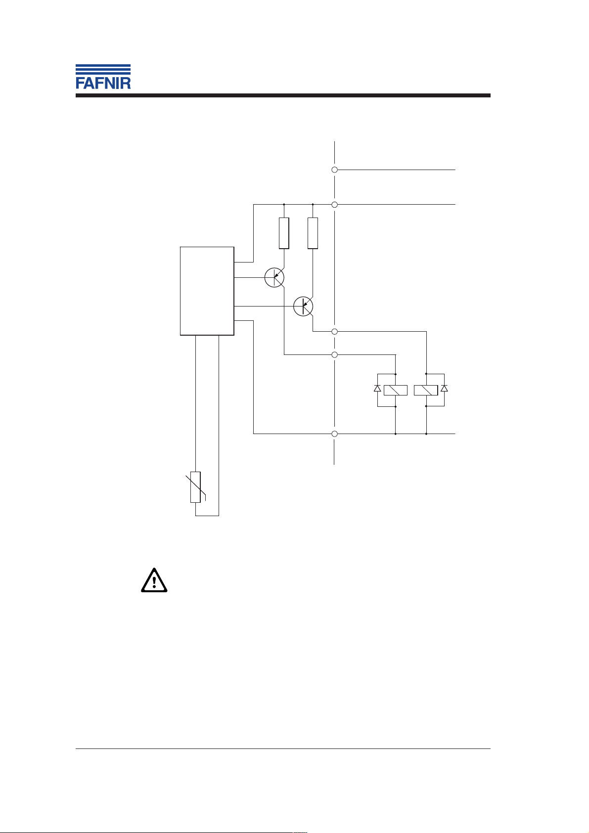
THE COOL ONE
5 green/yellow
measurement
evaluation unit
PIN 2 = relay 1 pulled up in submerged state
PIN 4 = relay 2 pulled up in emerged state
+T
PTC
Output: max. 80 mA
1 brown
R1 4,7 Ω
R2 4,7 Ω
T1
T2
black
4
white
2
relay 1
D1 D2
3
blue
relay 2
+
-
12
Fig. 3b: Terminal connection diagram – example
Prior to putting the level sensor into service, all the
possible devices of the limit value indicator must be
checked to determine correction connection and proper
operation. In addition, the electrical power supply of the
downstream devices must also checked.
THE COOL ONE

5 Technical data
Auxiliary power: 24 V DC (±10 %)
Power input: < 2 W
Temperature range: media
Pressure range: 0 to 2 bar
Media compatibility: Materials of media-contacted parts
Type 1 brass: 2.0332
-25 °C to +50 °C
environment
-25 °C to +80 °C
stainless steel: 1.4301 to 1.4571 (DIN 17440)
spring steel: 1.248, galvanised (DIN 17222)
soldering tin: L-Sn 40 Pb
Viton: FPM
linear polyester: Ultradur
Type 2 stainless steel: 1.4301 to 1.4571 (DIN 17440)
Viton: FPM
Type 3 stainless steel: 1.4301 to 1.4571 (DIN 17440)
Submergence
switching delay: < 2 seconds
Heating-up/release time
Ambient temperature: at -25 °C < 2 min
at +80 °C < 15 sec
Housing protective
system: IP 67
Outputs: 2 x PNP open collector, max. 80 mA
Dimensions: tube diameter: 16 x 1.5
probe length (types 1 and 2): 200 to
3,000 mm, standard up to 1,000 mm
response length (type 3): 34 mm
THE COOL ONE
13

14
THE COOL ONE
 Loading...