


Technical Documentation
Version: 4
Edition:
Art. no.: 350227
ME 6 …
Overfill prevention sensor tester
FAFNIR GmbH • Schnackenburgallee 149 c • 22525 Hamburg • Tel.: +49 / 40 / 39 82 07–0 • Fax: +49 / 40 / 390 63 39
2019-04

Table of contents
1 Overview .................................................................................................... 1
2 Safety instructions .................................................................................... 2
3 The ME 6 ... overfill prevention sensor testing device ......................... 3
3.1 Design and construction ................................................................................................................. 3
3.2 Function ................................................................................................................................................. 4
3.3 Scope of delivery ................................................................................................................................ 5
4 Operation ................................................................................................... 6
4.1 Fundamentals ...................................................................................................................................... 6
4.2 Start-Up ................................................................................................................................................. 8
4.2.1 Basic settings ....................................................................................................................................... 9
4.3 Testing the Overfill Prevention Sensor ..................................................................................... 11
4.3.1 Heating-up time ............................................................................................................................... 13
4.3.2 Switch-off time .................................................................................................................................. 13
4.3.3 QSS Code (ME 6 P) .......................................................................................................................... 15
4.4 Power saving (stand-by) mode and reactivation .................................................................. 15
4.5 Settings ................................................................................................................................................ 16
4.5.1 Country selection ............................................................................................................................. 17
4.5.2 Date and time .................................................................................................................................... 17
4.5.3 Backlight .............................................................................................................................................. 18
4.5.4 Touch screen calibration................................................................................................................ 18
4.5.5 QSS code identifiers ........................................................................................................................ 20
4.5.6 Readings archive............................................................................................................................... 21
4.5.7 Delete readings ................................................................................................................................. 21
4.5.8 Resetting to factory settings ........................................................................................................ 22
4.6 Power supply...................................................................................................................................... 22
4.6.1 Changing the rechargeable batteries ....................................................................................... 22
4.6.2 Regular charging of the rechargeable batteries necessary .............................................. 23
5 PC software .............................................................................................. 24
5.1 Driver installation ............................................................................................................................. 24
5.2 Starting the ME 6 Software ........................................................................................................... 24
5.2.1 Settings ................................................................................................................................................ 24
5.2.2 Records ................................................................................................................................................ 26
I Contents

© Copyright:
Reproduction and translation are permitted only with the written consent of FAFNIR GmbH. FAFNIR
GmbH reserves the right to carry out product alterations without prior notice.
6 Technical Data ......................................................................................... 27
7 List of figures ........................................................................................... 28
8 List of tables ............................................................................................. 28
9 Annex ........................................................................................................ 29
9.1 EC Declaration of Conformity ...................................................................................................... 29
9.2 EC Type Examination Certificate (ATEX) .................................................................................. 30
9.3 Instructions ......................................................................................................................................... 32
Contents II

1 Overview
Testing obligations in accordance with §§ 15 and 16 of the German Indus-
trial Safety Regulations (BetrSichV) and § 1 of the German Regulations on
Equipment Handling Substances Hazardous to Water (WasgefStAnlV). In
other countries, the corresponding national rules and regulations must be
observed.
When in operation, storage facilities for static tanks, filler points, petrol stations, airport refuelling equipment, and their components, e.g. overfill
prevention sensors, must be tested by an approved inspection agency prior
to commissioning, re-commissioning (after modifications subject to testing)
as well as repeatedly at specific testing intervals.
The system parts, e.g. overfill prevention sensors, must be tested by the operator or an authorised person as required by the manufacturer's operating
instructions at regular intervals.
The ME 6 … overfill prevention sensor testing device guarantees optimal and safe testing in accordance with prEN 13616-2 …
Three different types of these testing devices are available; they differ in the nature of
the application and the medium which is to be monitored:
• The ME 6 is used to test overfill prevention sensors without product coding.
• The ME 6 P is used to test overfill prevention sensors with product coding
in accordance with Quality Assurance systems (QSS).
• The ME 6 F is used to test overfill prevention sensors in LPG tanks.
In the following sections you will be guided by means of a detailed description
through the installation and commissioning of the ME 6 … overfill prevention sensor
testing device.
The ME 6 … overfill prevention sensor testing device may only be supplied
with power by 4 pcs NiMH rechargeable batteries (type AA 1.2 V, 2000 mAh).
Page 1/33 Design and construction

2 Safety instructions
The safety instructions in this manual are marked as follows:
If you do not comply with the safety instructions, there is a risk of accident,
or the device/system may be damaged.
Useful tips and information in this manual that should be observed appear
in italics and are identified by this symbol.
The ME 6 … overfill prevention sensor testing device is used to test overfill prevention
sensors in storage tanks. The testing device must be used exclusively for this purpose.
The manufacturer accepts no liability for any form of damage resulting from improper
use.
The ME 6 … overfill prevention sensor testing device has been developed, manufactured and tested in accordance with the latest good engineering practices and
generally accepted safety standards. Nevertheless, hazards may arise from its use. For
this reason, the following safety instructions must be observed:
Do not change or modify the testing device or add any equipment without
the prior consent of the manufacturer.
The operation and maintenance of the testing device must be carried out
by expert personnel only. Specialised knowledge must be acquired by regular training.
Operators, installers and service technicians must observe all applicable
safety regulations. This also applies to any local safety and accident prevention regulations which are not stated in this manual.
The manufacturer accepts no liability for any other batteries than the
required NiMH rechargeable batteries, see chapter 6, Technical Data.
Charging standard batteries instead of rechargeable batteries result in the
risk of fire or explosion.
Design and construction Page 2/33

USB socket
Type B
Battery compartment
Overfill prevention sensor coupling socket
Toggle switch
Measurement / USB
Touchscreen
3 The ME 6 ... overfill prevention sensor testing device
3.1 Design and construction
The ME 6 ... overfill prevention sensor testing device is used to test overfill prevention
sensors in accordance with prEN 13616-2. In order to do this, the testing device is
equipped with a socket coupler on a flexible spiral cable.
The testing device is operated by a touch screen.
Readings which has been saved can be transferred to a PC/laptop and archived by
means of software and the USB socket.
The testing device is powered by 4 pcs NiMH rechargeable batteries. These can be
replaced by the user. The batteries can be charged by a plug-in power supply or a
PC/lap top via the USB socket.
A toggle switch is used to move between the two operating modes Measurement and
USB connection/charging.
Figure 1: The ME 6 ... overfill prevention sensor testing device
Page 3/33 Design and construction

3.2 Function
The overfill prevention sensor is heated by the intrinsically safe electric current of the
ME 6 ... overfill prevention sensor testing device. The heating-up time needed is measured, assessed and presented on the screen. The switch-off time is treated in the same
way. The QSS coding is captured and also displayed (ME 6 P).
As the testing device has an intrinsically safe output circuit, it can be used for testing
all overfill prevention sensors approved by prEN 13616-2. The testing device itself must
be operated outside the Ex area. The type 903 socket coupler needed for the connection to the overfill prevention sensor is equipped with an appropriate length of cable.
The testing device must be equipped with a FAFNIR socket coupler type AS 903 for
checking the product identification.
The testing device is fitted with 4 pcs. NiMH rechargeable batteries. These batteries are
charged with the plug-in power supply via the USB socket or with the USB host of a
PC/laptop. They can only be charged when in USB mode. Depending on the nominal
capacity of the batteries, it takes about 10 hours to charge them. The batteries can be
freely exchanged.
Function Page 4/33

3.3 Scope of delivery
• The ME 6 ... overfill prevention sensor testing device with connected coupling
cable (with product identification, without product identification, or LPG)
• USB cable type A/B
• 4 pcs NiMH rechargeable batteries (type AA 1.2 V, 2000 mAh), plugged in
or separate
• Technical Documentation
Figure 2: Scope of delivery in carrying case as a set (e.g. ME 6 P)
Page 5/33 Scope of delivery

In this manual important activation fields are highlighted by a fingertip in symbolic
4 Operation
4.1 Fundamentals
The ME 6 ... overfill prevention sensor testing device is operated by a Touchscreen;
operations are activated by touching special activation fields. The user is generally
guided by icons or informative items of short text with the result that it is quite evident
in the individual screens which functions are triggered by the various activation fields.
The activation fields which regularly recur are listed below.
Confirmation, Activity successful, Amendments accepted
Refusal, Unsuccessful, Abort without amendments, Delete
Return to the previous screen
Input of figures
Figure 3: Activation fields of the graphical user guidance
form.
Excessive pressure can damage the screen. Gently touching the screen is
sufficient to operate it.
If no reaction is produced, the touch screen is perhaps decalibrated. In this
case, all that is needed to start the calibration process is to touch the screen
with a finger for about 5 seconds.
Fundamentals Page 6/33

USB socket
Figure 4: Status display
When in the main screens, the date, time, memory occupancy, and battery status is
indicated in the upper line of the screen.
< Measuring range data storage over 50% full
< Batteries about 1/3 discharged
< Memory almost empty
< Batteries being charged
< Memory almost full
< No batteries inserted; testing device being powered via the
Page 7/33 Fundamentals

4.2 Start-Up
If the testing device was supplied with 4 unplugged separate NiMH rechargeable batteries, first the batteries must correctly be inserted for starting up. Open the battery
compartment on the rear side of the testing device with a Philips screwdriver and insert the batteries according to the symbols in the battery compartment. The testing
device starts for the first time to enter the basic settings.
Figure 5: Battery compartment in the rear side of the testing
device
Before starting up the testing device, the rechargeable batteries must first be
charged. A complete charging takes about 10 hours.
Start-Up Page 8/33

a)
b)
c)
a) b)
a) Successful b) Unsuccessful
4.2.1 Basic settings
After the first start or reset to the factory settings, the basic settings are to be set displayed automatically in sequence. The touch screen must then be calibrated. To do
this, each of the icons in the 4 corners must be touched until the next one is shown. A
point situated in the middle must be touched as final test.
Figure 6: Calibrating the touch screen
The calibration can fail if the points are incorrectly touched. In this case the basic settings are interrupted and the standard values are loaded. However, it is still possible to
configure the testing device at a later time by means of the graphical user interface.
Figure 7: Results of touch screen calibration
Page 9/33 Start-Up

a) b) c)
Figure 9: Date and time b) Setting the date c) Setting the time
The country is selected after calibrating the touch screen. This determines the user
interface language and, when applicable, the assessment methods. Select by touching
the relevant field.
Figure 8: Country selection
The real time clock is adjusted after selecting the country.
The date can be set in the first screen and the time in hours and minutes in the second
screen by touching + and – .
Start-Up Page 10/33

These tests can also be carried out individually if they are selected via
4.3 Testing the Overfill Prevention Sensor
The operating mode Measurement must be set in order to be able to test overfill prevention sensors with the ME 6 ... overfill prevention sensor testing device. To set the
mode, push the toggle switch on the upper side of the testing device into the corresponding position.
Figure 10: Toggle switch in the measuring position
Testing the heating-up time of an overfill prevention sensor starts as soon as an overfill
prevention sensor is connected to the socket coupler and recognised by the system.
If the test fails to start, the resistance is outside the applicable figures; this
is caused, for example, by a short circuit or a cable breakage or by the toggle switch being in the wrong position.
The standard test includes the test of the heating-up time and optionally after successful completion the test of the switch-off time. This can be declined in a selection
dialogue. For ME 6 P the standard test includes the product recognition (QSS code).
the main menu in the operating mode “Measurement “.
Figure 11: Main menu, operating mode "Measurement"
Page 11/33 Testing the Overfill Prevention Sensor

The faults SHORT CIRCUIT and RESISTANCE TOO HIGH can occur in all tests, which
stop the test immediately. In the case of the RESISTANCE TOO HIGH fault, the testing
device has perhaps not been switched to the Measurement mode with the result that
the overfill prevention sensor is not connected to the heating circuit. Or a cable is
broken.
Figure 12: Fault display "Short circuit" and "Resistance too high"
Testing the Overfill Prevention Sensor Page 12/33

a) b) c)
Test for heating-up time
Test result
4.3.1 Heating-up time
The test starts automatically when the overfill prevention sensor is connected to the
socket coupler or if the field HEATING-UP TIME is selected in the main menu.
For ME 6 P the testing device attempts to read the QSS code. The code is displayed
and the actual measurement commences. The overfill prevention sensor is heated up
and the progress of the change in resistance is displayed graphically. If the target resistance value is not reached within 180 seconds, the measurement is aborted with a
fault. At the end of a successful test, a dialogue asks if the TEST FOR SWITCH-OFF TIME
is to be performed.
Figure 13:
b) Error message c)
4.3.2 Switch-off time
The TEST FOR SWITCH-OFF TIME can be performed as an option immediately after a
successful TEST FOR HEATING-UP TIME. A corresponding dialogue is superimposed on
the display for this purpose. The test can also be selected manually by selecting the
field SWITCH-OFF TIME in the main menu.
The switch-off time is tested by heating the overfill prevention sensor. This is displayed
by the message HEAT. After a target temperature has been reached, the message
changes to READY and a 2-second count-down is displayed which ends with the command IMMERSE. The overfill prevention sensor must now be manually immersed in a
test liquid. The time needed for the overfill prevention sensor to fall to a pre-set value
is measured.
Page 13/33 Testing the Overfill Prevention Sensor

from the heating-up phase to the "Immerse" command after the count-down
Figure 14: Images showing the test of the switch-off time
Figure 15: Images relating to the immersion of the overfill prevention sensor
with possible measuring results
Testing the Overfill Prevention Sensor Page 14/33

4.3.3 QSS Code (ME 6 P)
This test is carried out at the same time as the TEST FOR HEATING-UP TIME is performed. The test can also be started manually by selecting the field QSS CODE in the
main menu.
Figure 16: Checking the QSS code (ME 6 P)
4.4 Power saving (stand-by) mode and reactivation
If not connected to a USB power supply, the testing device switches to a stand-by
mode after 30 seconds of inactivity. The screen is switched off in this mode. The testing
device can be reactivated by touching the screen for about 2 seconds or connecting an
overfill prevention sensor. It is therefore also possible to take a measurement directly
after the stand-by mode.
Page 15/33 Power saving (stand-by) mode and reactivation
a)
b)
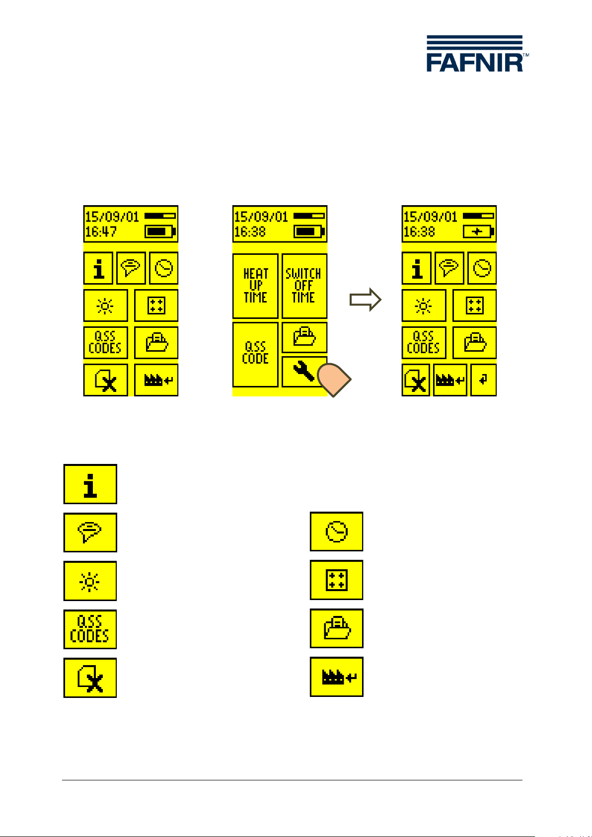
4.5 Settings
The settings of the ME 6 ... overfill prevention sensor testing device can be adjusted
using the ME 6 PC software when in USB operating mode (see Section 5 PC software)
or directly on the testing device. In USB operating mode, the settings can be accessed
directly via the main menu; when in Measurement mode, the spanner (wrench) icon
must be selected.
in USB mode
Figure 17: Settings
Device information
Select language / country code
Set screen brightness
Edit QSS code identifiers
Delete saved data
in measuring mode
settings
Set date and time
Calibrate touch screen
Display saved data
Reset to factory settings
Figure 18: Symbols of settings
Settings Page 16/33

Figure 19: Country selection
a) b)
4.5.1 Country selection
Country selection determines the user interface language and, when applicable, the
assessment methods. Selection is by touching the relevant field.
4.5.2 Date and time
The date can be set by touching + and - in the first screen. The time can be set in
hours and minutes in the second screen. The X button aborts the process; the current
date is not changed.
Figure 20: Setting the date and time
Page 17/33 Settings

Figure 21: Setting the screen brightness
a)
b)
4.5.3 Backlight
The backlight is set to the required brightness by dragging the slide. Reduced brightness increases the testing device's operating time.
4.5.4 Touch screen calibration
The touch screen can be calibrated to increase the accuracy of the inputs on the sensitive screen. To do this, each of the icons in the 4 corners must be touched until the
next one is shown. A point situated in the middle must be touched as the final test.
Figure 22: Calibrating the touch screen
Settings Page 18/33
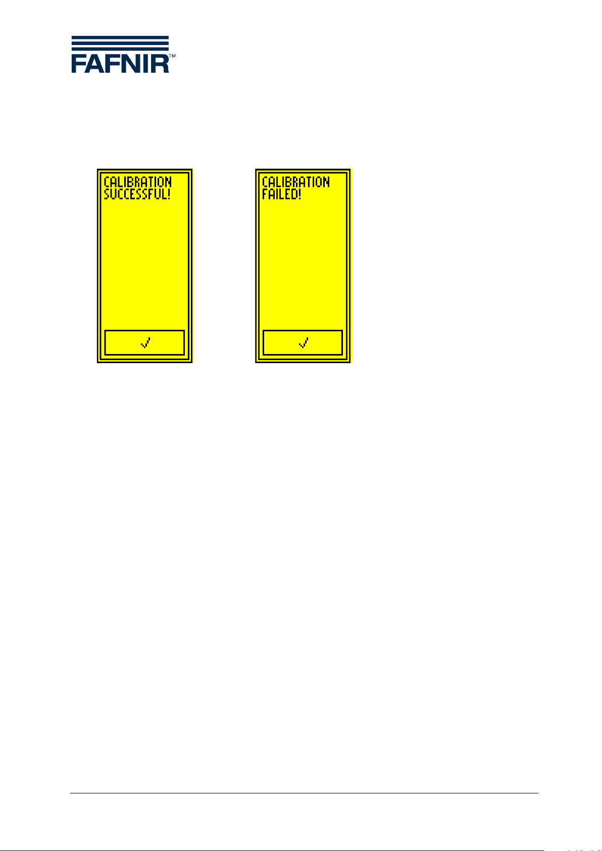
a) b)
a) Successful calibration b) Unsuccessful calibration
The calibration can fail if the points are incorrectly touched. In this case the basic settings are interrupted and the standard values are loaded. However, it is still possible to
configure the testing device at a later time by means of the graphical user interface.
Figure 23: Results of the touch screen calibration
Page 19/33 Settings

a)
b)
a) Example of QSS identifiers b) Editing a QSS identifier
4.5.5 QSS code identifiers
On ME 6 P the identifiers can be added to the numeric QSS codes. A 7-character identifier can be programmed for each of the 6 possible codes. The identifier can be edited
by touching the relevant field in the overview. This changes the program to the Editor
view. The field with the current text is located at the top. A keyboard to enter the characters is superimposed in the middle. The control symbols are located in the bottom
row.
A accepts the current text; X deletes the last character; switches to the overview
without adopting any changes.
Figure 24: ME 6 P QSS codes and identifiers
Settings Page 20/33

<
Record number Index / entire number (e.g. 16/303)
<
QSS code Code and identifier (e.g. 1 E5) or
"NO QSS“ (if no code)
<
Date yyyy/mm/dd (e.g. 2015/10/01)
<
Time hh:mm (e.g. 16:41)
<
Heating-up time
with heating-up time (e.g. 15 s) or
(
<
Switch-off time
with switch-off time (e.g. 0.3 s) or
(
<
-1 or +1: Display previous or next record
<
-10 or +10: Jump 10 records back or forward
Figure
4.5.6 Readings archive
The data from completed measurements (at least the heating-up test) are archived in
the instrument's memory. If the memory for the readings is full no further measurements can be recorded. In this case, the data in the testing device should be
downloaded to a PC/laptop via a USB connection and the memory cleared.
0.5 s … 180 s) X with heating-up time "<0.5 s" or ">180 s"
0 s … 2 s) X with switch-off time > 2 s (e.g. X 2.3 s) o
no test
25: Display of saved readings in the archive
4.5.7 Delete readings
No further measurements can be recorded if the memory for the readings is full. In this
case, the data in the testing device should be downloaded to a PC/laptop via a USB
connection to clear the memory.
Figure 26: Deleting the readings memory
Page 21/33 Settings

4.5.8 Resetting to factory settings
The ME 6 ... overfill prevention sensor testing device can be reset to the factory settings. In this case all settings are deleted and the readings memory emptied. Once
deletion is complete the testing device restarts with the basic settings.
Figure 27: Resetting the testing device to factory settings
4.6 Power supply
The ME 6 ... overfill prevention sensor testing device is operated in measurement mode
by NiMH rechargeable batteries. The charge level is indicated in the status bar. If this is
low, the testing device must be recharged. This is done via the USB connection.
4.6.1 Changing the rechargeable batteries
The rechargeable batteries can be changed at any time. To do this, the cover of the
battery compartment must be opened with a Philips screwdriver and the rechargeable
batteries replaced by new ones. Battery alignment is shown by symbols in the battery
compartment. The rechargeable batteries need a nominal capacity of 2000 mAh. They
allow a number of approx. 150 complete measurements.
If it is likely that the instrument would not be used for a lengthy period, the
batteries should be removed and stored in the supplied case.
Only NiMH rechargeable batteries (type AA 1.2 V, 2000 mAh) may be used.
Power supply Page 22/33

Figure 28: Tog g le switch in Charge position
4.6.2 Regular charging of the rechargeable batteries necessary
When charging the batteries, the toggle switch must be set to Charge. The testing
device can then be connected to a computer or a USB plug-in power supply (5 V DC)
with the USB cable provided. The testing device immediately starts to charge the batteries. The current status is indicated in the upper status bar.
Depending on the capacity of the batteries used and their charge, charging the batteries from empty can take more than a day. If the testing device is used every day it is
recommended that the batteries are charged over the week-end.
When connecting to USB hubs with a passive supply, care must be taken
that without active supply these often limit the maximum current to 100 mA.
In this case it is not possible to charge the batteries.
To prevent a deep discharge of the batteries, they should be regularly
charged until they are full and at least every 20 days.
Batteries being charged
Figure 29: Charge statuses displayed in the status bar
Page 23/33 Power supply
Batteries fully charged
No batteries present / batteries defective

ME 6 tab
QSS identifiers
Device information and
s
Message and
communication window
Language
5 PC software
5.1 Driver installation
As soon as the ME 6 ... overfill prevention sensor testing device is connected to a Windows® computer, the operating system will look for a driver. If the computer is
connected to the Internet, the driver will normally be installed automatically. Manual
installation is also possible with the drivers provided by FAFNIR.
5.2 Starting the ME 6 Software
The software is launched by starting ME6.exe. An ME 6 ... overfill prevention sensor
testing device which is connected is automatically recognised and the settings are
uploaded.
The driver installation must be carried out before the start of the ME 6 soft-
ware, otherwise an error message will be displayed and the software will not
be executed.
5.2.1 Settings
The testing device's settings are displayed in the tab ME 6 and can be edited.
ettings
Figure 30: ME 6 software, device information and settings
Driver installation Page 24/33

The corresponding field of the date must be
ton which appears.
Setting
Use the mouse to move the slide between the
Calibrating
screen.
The calibration of the instrument's touch screen
tion 4.5.4)
The 6 fields on the right-hand side of the user
th a
ton which appears.
Tab le 1: Software settings
Setting the
date
and time
Selecting
the country
code
the brightness
the touch
clicked on with the mouse; the required date can
then be set with the mouse wheel or the arrows.
The selected date is set by clicking on the
Open the list of country identifiers by clicking on
the arrow and select the required country by clicking on it.
minimum and maximum values.
can be started by clicking on the button (see Sec-
but-
interface show the identifiers currently allocated to
Editing
QSS identifiers.
the QSS codes. Any required identifiers wi
maximum of 7 characters can be entered in these
fields.
The selected date is set by clicking on the
but-
Page 25/33 Starting the ME 6 Software
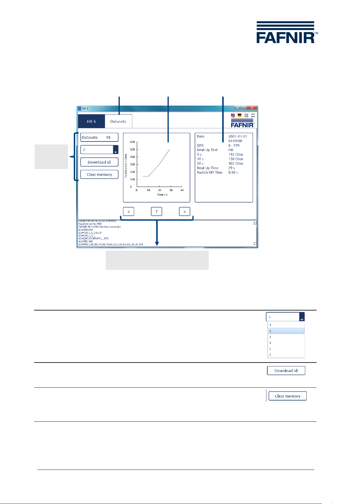
Select
Open the list of record indices by clicking on the arrow
Downloading
Clicking on the button downloads all saved data of the
Delete
By clicking on the button, the testing device's memory is
Table 2: Read out the readings in the memory
Heating-up
curve
Readings
Last/next record with display
of the current index
Control
tab
5.2.2 Records
tools
Records
Figure 31: ME 6 software, records
record
and saving data
memory.
and then select the required one.
testing device and saves it in a file specified by the user.
emptied after a prompt for confirmation. Data saved up
to that point is then no longer available.
Starting the ME 6 Software Page 26/33

Temperature
range
Overfill prevention
identification
Spiral cable (max. 3 m) with
Overfill prevention
identification
Spiral cable (max. 3 m) with
Overfill prevention
petroleum gas
Spiral cable (max. 3 m) with
Battery Type
Size
Nominal Voltage [V]
Capacity [mAh]
NiMH
AA
1.2
2000
6 Technical Data
Type
ME 6
ME 6 P
ME 6 F
Table 3: Technical data of the ME 6 … types
Table 4: Battery type
Measuring range
sensor without product
sensor with product
sensor in liquefied
-20 … +50 °C
-20 … +50 °C
-20 … +50 °C
Connection
Socket coupler type 903,
USB type B
Socket coupler type AS 903,
USB type B
Socket coupler type CEE,
USB type B
Page 27/33 Starting the ME 6 Software

7 List of figures
Figure 1: The ME 6 ... overfill prevention sensor testing device ...............................................3
Figure 2: Scope of delivery in carrying case as a set (e.g. ME 6 P) ..........................................5
Figure 3: Activation fields of the graphical user guidance.........................................................6
Figure 4: Status display ...........................................................................................................................7
Figure 5: Battery compartment in the rear side of the testing device ...................................8
Figure 6: Calibrating the touch screen ..............................................................................................9
Figure 7: Results of touch screen calibration ..................................................................................9
Figure 8: Country selection ................................................................................................................. 10
Figure 9: Date and time b) Setting the date c) Setting the time ................................. 10
Figure 10: Toggle switch in the measuring position ............................................................... 11
Figure 11: Main menu, operating mode "Measurement"...................................................... 11
Figure 12: Fault display "Short circuit" and "Resistance too high" ..................................... 12
Figure 13: Test for heating-up time b) Error message c) Test result............................... 13
Figure 14: Images showing the test of the switch-off time .................................................. 14
Figure 15: Images relating to the immersion of the overfill prevention sensor ............ 14
Figure 16: Checking the QSS code (ME 6 P) ............................................................................... 15
Figure 17: Settings ............................................................................................................................... 16
Figure 18: Symbols of settings ........................................................................................................ 16
Figure 19: Country selection ............................................................................................................ 17
Figure 20: Setting the date and time ............................................................................................ 17
Figure 21: Setting the screen brightness ..................................................................................... 18
Figure 22: Calibrating the touch screen ....................................................................................... 18
Figure 23: Results of the touch screen calibration ................................................................... 19
Figure 24: ME 6 P QSS codes and identifiers ............................................................................. 20
Figure 25: Display of saved readings in the archive ................................................................ 21
Figure 26: Deleting the readings memory .................................................................................. 21
Figure 27: Resetting the testing device to factory settings .................................................. 22
Figure 28: Toggle switch in Charge position .............................................................................. 23
Figure 29: Charge statuses displayed in the status bar .......................................................... 23
Figure 30: ME 6 software, device information and settings ................................................. 24
Figure 31: ME 6 software, records .................................................................................................. 26
8 List of tables
Table 1: Software settings ................................................................................................................. 25
Table 2: Read out the readings in the memory ......................................................................... 26
Table 3: Technical data of the ME 6 … types .............................................................................. 27
Table 4: Battery type ........................................................................................................................... 27
Starting the ME 6 Software Page 28/33


Page 1/2
FAFNIR GmbH ⚫ Schnackenburgallee 149 c ⚫ 22525 Hamburg ⚫ Tel.: +49 / (0)40 / 39 82 07-0 ⚫ www.fafnir.de ⚫ info@fafnir.de
Instructions IBExU 15 ATEX 1080 X
Overfill prevention sensor testing device type ME 6 … Version: 06.2015
I Range of application
The purpose of the overfill prevention sensor testing device type ME 6 … is to test the function of overfill
prevention sensors by means of the PTC resistor principle. The overfill prevention sensor may be in
Zone 0 during testing, but the overfill prevention sensor testing device may only be operated outside
the potentially explosive area.
II Standards
The OPS testing device is designed in accordance with the following European standards
EN 60079-0:2012 + A11:2013 Equipment – General requirements
EN 60079-11:2012 Equipment protection by intrinsic safety "i"
III Instructions for safe …
III.a … use
The overfill prevention sensor testing device acts as associated equipment and is not approved for use
in potentially explosive areas. The intrinsically safe sensor circuit can be brought into Zone 0 and is
suitable for all gas groups (IIA, IIB and IIC).
Because of the construction of the socket couplers the connection of the overfill prevention sensor must
be in Zone 1 or in a less hazardous area. The socket coupler type 903 and the CEE socket coupler are
classified as simple electrical equipment. The socket coupler type AS 903 is also marked and is suitable
for use in Zone 1 or a less hazardous area.
If the connection of the overfill prevention sensor is in potentially explosive areas with gases in temperature class T5 or T6*, the overfill prevention sensor testing device with product identification type ME 6 P
and the socket coupler type AS 903 may not be used.
The approval applies to equipment types
ME 6 OPS testing device without product identification (with socket coupler type 903)
ME 6 F OPS testing device for LPG overfill prevention sensors (with CEE socket coupler)
ME 6 P OPS testing device with product identification (with socket coupler type AS 903)
III.b … assembling and dismantling
The overfill prevention sensor testing device may only be assembled or dismantled when no overfill
prevention sensor is connected!
Only the battery compartment may be opened. Opening the case is not allowed as this could be damaged and the approval would therefore be void.
III.c … installation
No installation is necessary to operate the device.
III.d … adjustment
No safety-related arrangement or fittings are necessary to operate the device.
III.e … putting into service
The overfill prevention sensor testing device may only be connected to an overfill prevention sensor if
nothing is connected to the USB port.
The overfill prevention sensor may be connected and disconnected while the overfill prevention sensor
testing device is in operation.
* Overfill prevention sensor testing devices using the PTC resistor principle are certified to T3, maximum T4

Page 2/2
FAFNIR GmbH ⚫ Schnackenburgallee 149 c ⚫ 22525 Hamburg ⚫ Tel.: +49 / (0)40 / 39 82 07-0 ⚫ www.fafnir.de ⚫ info@fafnir.de
III.f … maintenance (servicing and emergency repair)
The device is normally maintenance-free. In the event of a defect, the device must b e s end back to
FAFNIR or one of its agencies.
The overfill prevention sensor testing device may only be charged via a USB connection if no overfill
prevention sensor is connected.
If the batteries used are found to be defective they may be replaced by batteries of the same type.
IV Equipment marking
1
Manufacturer:
FAFNIR GmbH, 22765 Hamburg
2
Type designation:
ME 6 …
3
Certificate number:
IBExU 15 ATEX 1080 X
4
Ex marking:
OPS testing device type ME 6 …:
II (1) G
[Ex ia Ga] IIC
Socket coupler type AS 903:
II 2 G
Ex ia IIC T4 Gb
5
CE marking:
0044
6
Technical data:
Ta ≤ +50 °C
Uo 20.8 V
Io 133 mA
Po 690 mW
Li 10 µH
Ci 2 nF
Lo 500 µH
Co 110 nF
V Technical data
To charge the batteries (secondary cells), the overfill prevention sensor testing device is suitable for
connection to a USB interface (5 V; 500 mA).
The electric circuit of the sensor is designed with "intrinsic safety" (ia) ignition protection class with a
linear output characteristic. The safety-relevant data are as follows:
Output voltage Uo 20,8 V
Output current Io 133 mA
Output power Po 690 mW
Internal, externally effective inductance Li 10 µH
Internal, externally effective capacitance Ci 2 nF
Permissible external inductance Lo 500 µH
Permissible external inductance Co 110 nF
The overfill prevention sensor testing device can be used in the following ambient temperature range:
Ambient temperature range Ta = -20 °C … +50 °C
The overfill prevention sensor testing device has a degree of protection provided by enclosure of:
Degree of protection provided by enclosure IP30
VI Special conditions of use
1. It is not permitted to connect simultaneously the overfill prevention sensor at sensor connector and
the auxiliary energy at USB connector.
2. If the connector of the overfill prevention sensor is located in a potentially explosive atmosphere of
gases with a temperature class T5 or T6, the type ME 6 P respectively connector type AS 903 is not
permitted for use.

Blank Page

Blank Page

Blank Page

FAFNIR GmbH
Schnackenburgallee 149 c
22525 Hamburg, Germany
Tel.: +49 / 40 / 39 82 07 – 0
Fax: +49 / 40 / 390 63 39
E-mail: info@fafnir.com
Web: www.fafnir.com
 Loading...