

Page 1

1
Code 924.812.030 (rev. 0720)
Gentile Signora, Egregio Signore
ci congratuliamo con Lei per la Sua nuova Faema.
Con questo acquisto Lei ha scelto una macchina per caffè
espresso d'avanguardia costruita secondo i più avanzati
principi della tecnica moderna; una macchina che non
soltanto è in grado di offrirLe una perfetta sintesi di efficienza
e funzionalità ma mette a Sua disposizione tutti gli strumenti
per darLe la "sicurezza di lavorare meglio".
Il consiglio di dedicare un poco di tempo alla lettura di
questo Libretto di Uso e Manutenzione nasce dal desiderio
di aiutarLa a prendere confidenza con la Sua nuova
macchina; desiderio che siamo certi Lei condividerà
pienamente.
Le auguriamo buon lavoro.
GRUPPO CIMBALI S.p.A.
Dear Customer,
We congratulate with you for your new Faema.
With this purchase you’ve chosen an up to date machine,
built after the most advanced principles of modern
technology, a unit, which gives you not only a perfect
synthesis of efficiency and functonality, but puts also at
your disposal everything you need for a good working.
The advice we give you of spending a bit of your time in
reading this manual comes from our desire of helping
you in reaching a good knowledge of your new machine.
We’re sure of finding you of the same advice.
With our best wishes of a good work.
GRUPPO CIMBALI S.p.A.
I GB
Sehr geehrter Kunde,
Wir gratulieren lhnen zur lhrer neuen Faema und heissen
sie in unserem Kundenkreis willkommen. Mit diesem
Gerät haben Sie eine Maschine ausgewählt, die nach
den letzten technischen Entwicklungen auf diesem Sektor
gebaut wurde: eine Maschine die mehr als die perfekte
Synthese zwischen Leistungsfähigkeit und Funktionalität
anbietet: nämlich die Gewissheit, ein betriebsicheres,
seinen Aufgaben gewachsenes Gerät zu besitzen.
Wir empfehlen lhnen dieses Handbuch zum Studium,
wissend, dass Sie damit lhre Kenntnisse über lhre neue
Maschine vertiefen können.
Wir verbleiben mit unseren besten Wünschen für ein
gutes Arbeiten mit lhrem neuen Gerät.
GRUPPO CIMBALI S.p.A.
Cher Client,
Nous vous félicitons pour l’acquisition de votre nouvelle
Faema.
Avec cet achat vous avez choisi une machine à café
moderne, construite selon les principes les plus avancés
de la technique d’aujourd’hui, une machine qui vous offre
une parfaite synthèse d’efficacité et de fonctionnalite et
qui met ê votre disposition tout ce dont vous avez besoin
pour obtenir un bon travail.
Le conseil que nous vous donnons de consacrer un peu
de votre temps à la lecture de cette brochure vient du désir
que nous avons de vous aider à atteindre une bonne
connaissance de votre nouvelle machine.
Nous sommes certains que vous serez du même avis.
Avec nos meilleurs souhaits de bon travail.
GRUPPO CIMBALI S.p.A.
F D
Estimado Cliente,
nos felicitamos con Usted para su nueva Faema.
Con esta compra Usted ha escogido una máquina para
café a la vanguardia, construida según los principios
mas adelantados de la técnica moderna; una máquina
que no sólo le ofrece una perfecta eficiencia y
funcionalidad, mas también le da todo lo que Usted
necesita para alcanzar la garantía de un buen trabajo.
Le aconsejamos de poner un poco de su atención en la
lectura de este manual, consejo que nos viene del deseo
de aiudarle a lograr un buen conocimiento de su nueva
máquina.
Estamos seguros que Usted tiene la misma opinión.
Con un deseo particular de buen trabaio.
GRUPPO CIMBALI S.p.A.
Exmª. Senhora, Exm°. Senhor,
Felicitamo-nos e a si pela sua nova máquina para café.
Com deste acquisição escolheu uma máquina para
café de vanguarda, construída segundo os mais
avançados principios da técnica moderna, uma máquina
que está não somente em condições de lhe oferecer
uma sintese perfeita de eficiência e funcionalidade, mas
põe à sua disposição todos os instrumentos para darlhe a "segurança de trabalhar melhor".
O conselho de dedicar um pouco de tempo à leitura deste
livreto de uso e manutenção nasce do desejo de o ajudar
a tomar familiaridade com a sua nova máquina; desejo
que estamos certos partilhará plenamente.
Desejamos-lhe bom trabalho.
GRUPPO CIMBALI S.p.A.
E
P
Page 2
2
E92/A
Manuale - Manual - Manuel - Handbuch - Manual - Manual
Leggere attentamente le avvertenze contenute nel
presente manuale, prima di utilizzare o manipolare in
qualsiasi modo la macchina, in quanto forniscono importanti
indicazioni riguardanti la sicurezza d'uso della stessa.
La macchina per caffè è prevista unicamente per la
preparazione di caffè espresso e bevande calde mediante
acqua calda o vapore e per il preriscaldamento delle tazzine.
Ogni utilizzazione diversa da quella sopra descritta è
impropria e può essere fonte di pericolo per persone e
macchina.
Il produttore non assume responsabilità alcuna in caso di
danni risultanti da un uso improprio della macchina per caffè.
Read the instructions in this manual carefully before
using or handling the machine in any way. The
instructions provide important information regarding the
safety precautions to be followed.
The coffee machine is to be used solely for preparing
expresso coffee and hot drinks made with hot water or steam
and for heating cups.
Improper use of the machine for operations other than the
above can constitute a safety risk to persons and to the
equipment.
The producer disclaims all liability in case of damage due to
improper use of the coffee machine.
Leer cuidadosamente las advertencias contenidas en
el presente manual antes de utilizar o manejar de
cualquier forma la máquina, ya que proporcionan importantes
indicaciones sobre la seguridad de manejo de la misma.
La máquina para café sólo está prevista para la preparación
de café expreso y bebidas calientes mediante agua caliente
o por vapor, así como para el calentamiento de las tacitas.
Cualquier utilización diferente de la anteriormente descrita
es impropia y puede ser fuente de peligro para las personas
y la máquina.
El fabricante no se asume ninguna responsabilidad en el
caso de daños causados por un empleo impropio de la
máquina para café.
Lire attentivement les informations contenues dans
ce manuel avant que vous n’utilisiez et que vous ne
manipuliez la machine à café de manière erronnée. En effet,
ces informations vous fourniront d’importantes indications
concernant la sécurité d’utilisation de votre machine à café.
La machine à café n’est apte qu’à la préparation de cafés
espresso et de boissons chaudes, en n’utilisant que de l’eau
chaude ou de la vapeur , ou encore, pour chauffer vos tasses.
Toute opération différente de celles qui sont indiquées cidessus ne peut être effectuée car elle pourrait être la source
de dangers pour les personnes et pour la machine même.
Le producteur ne s’assume aucune responsabilité dans le
cas de dommages provenant d’une utilisation incorrecte de
la machine à café.
Bevor Sie die Maschine einschalten oder gebrauchen,
sollten Sie die vorliegende Bedienungsanleitung
genau durchlesen, da sie wichtige Angaben zum sicheren
Einsatz der Maschine enthält.
Die Maschine darf ausschließlich zur Zubereitung von
Espressokaffee, die Heißwasser- und Dampfausgabe zur
Zubereitung von Getränken (z. B. für Teewasser oder zum
Milchaufschäumen) oder zum Vorwärmen von Tassen benutzt
werden.
Alle anderen Arten des Einsatzes gelten als unsachgemäß
und beinhalten die Gefahr der Verletzung oder der
Beschädigung der Maschine.
Der Hersteller übernimmt keine Haftung für Schäden oder
Verletzungen, die auf einen unsachgemäßen Einsatz der
Kaffeemaschine zurückzuführen wären.
Ler atentamente as advertências contidas no
presentemanual, antes de utilizar a máquina ou de a
manusear, visto fornecerem indicações importantes relativas
à segurança de utilização da mesma.
A máquina de café destina-se unicamente à preparação de
café expresso e bebidas quentes com água quente ou vapor
e para o aquecimento prévio das chávenas.
Qualquer utilização diferente das acima descritas é
imprópria, podendo tornar-se fonte de perigo para as
pessoas e a máquina.
O construtor não assume nenhuma responsabilidade
perante danos decorrentes de um uso impróprio da máquina
de café.
P
I GB
F D
E
Page 3
3
Indice - Index - Index - Inhaltsverzeichnis - Indice - Indice
Pag. - Page - Page
Seite - Pag. - Pag.
Descrizione - Description - Description - Beschreibung - Descripcíon - Descrição 4
Installazione - Installation - Installation - Installation - Instalación - Instalação 8
Messa fuori servizio definitiva - Dismantling the machine
Endgültige Ausserbetriebstellung - Mise hors service definitive 27
Interrupción definitiva del servicio - Colocação fora de serviço definitiva
Uso - Dichiarazione di Conformità CE 29
PROGRAMMAZIONE - MODALIT A' UTENTE 39
Use - EC Declaration of Conformity 49
PROGRAMMING - USER MODE 59
Usage - Certificat de Conformité CE 69
PROGRAMMATION - MODALITES USAGER 79
Gebrauch - EG - Konformitätserklärung 89
PROGRAMMIERUNG DURCH BENUTZER 99
Uso - Declaraciòn de Conformidad CE 10 9
PROGRAMACIÓN - MODALIDAD USUARIO 1 19
Uso - Declaração de Conformidade CE 12 9
PROGRAMAÇÃO - MODALIDADE DO UTILIZADOR 139
Programmazione - Modalità tecnico 149
Programming - Engineer mode 161
Programmation – Modalités techniques 173
Programmierung durch Monteur 185
Programación - Modalidad técnico 197
Programação - Modalidades Técnico 209
Smontaggio - Disassembly - Demontage - Abmontierung - Desmontaje - Desmontagem 22 1
Regolazioni - Setting - Reglages - Einstellungen - Regolaciones - Regulações 223
Schema elettrico - Wiring diagram - Schema electrique 229
Schaltplan - Esquema electrico - Esquéma electrico
Circuito idraulico - Hydraulic circuit - Circuit hydraulique 23 6
Hydraulikplan - Circuito hidraulico - Circuito hidráulico
Service Line 240
I
GB
P
E
D
F
Questi capitoli del manuale sono ad uso del personale
tecnico autorizzato.
The procedures described in this manual must be performed
by qualified technicians.
Ces châpitres du manuel sont utilisables par le personnel
technique autorisé.
Die Kapitel der vorliegenden Bedienungsanleitung richten
sich an zur Aufstellung, Demontage und Programmierung
befugte Techniker.
Estos capítulos del manual son para uso del personal técnico autorizado.
Estes capítulos do manual deverão ser utilizados pelo
pessoal técnico autorizado
I
GB
P
E
D
F
Page 4
4
E92/A
14
16
11
18
9
21
13
17
10
19
20 8
22
25
23
651231a 4
15
12
cba
15Idp
24
323733 34 3531 36
26 27 28 2930
91
Page 5

5
Legenda - Legend - Legende - Legende - Leyenda - Legenda
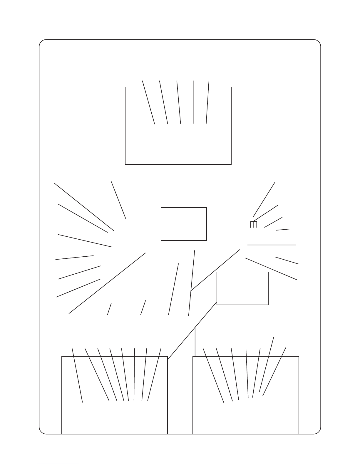
LEGENDA
1 Interruttore generale
1a Interruttore inserimento resistenze caldaia
2 Spia luminosa macchina accesa (verde)
3 Spia luminosa inserimento resistenze caldaia
(arancione)
4 Spia luminosa (livello) carico acqua in caldaia
(rossa)
5 Spie luminose scaldatazze acceso (3 LED)
6 Pulsante scaldatazze
8 Manometro rete/ pompa
9 Lancia destra erogazione vapore
10 Lancia erogazione acqua calda
11 Leva erogazione vapore lancia (9 dx)
12 Pulsante vapore automatico AUTOSTEAM (*)
13a Pulsante erogazione acqua calda (dose 1/STOP)
13b Pulsante stop - continuo acqua calda
13c Pulsante erogazione acqua calda (dose 2/STOP)
14 Display alfanumerico
15 Display pubblicitario
15Idp Interruttore display pubblicitario
16 Pulsante latte (vapore *)
17 Leva erogazione vapore lancia (20 sx)
18 Cappuccinatore (*)
19 Indicatore livello ottico acqua in caldaia
20 Lancia sinistra erogazione vapore
21 Portafiltro per una tazza
22 Leva riempimento manuale acqua in caldaia
23 Finestrella per controllo fiamma
24 Manopola-pulsante rubinetto gas (*)
25 Portafiltro per due tazze
26 Pulsante erogazione un caffè ristretto
27 Pulsante erogazione due caffè ristretti
28 Pulsante erogazione un caffè lungo
29 Pulsante erogazione due caffè lunghi
30 Pulsante erogazione continua/STOP
31 Pulsante visualizzazione quadri di programmazione
32 Pulsante PROG
33 Pulsante freccette
34 Pulsante incremento valori (+)
35 Pulsante diminuzione valori (-)
36 Pulsante reset
37 Tastiera di programmazione
91 Bacinella appoggiatazze
I componenti -*- sono applicati solo su alcune
configurazioni di prodotti.
LEGEND
1 Main switch
1a Boiler heat resistance switch
2 Machine “ON” indicator light (green)
3 Boiler heating element pilot light (orange)
4 Boiler water fill indicator (level) light (red)
5 Cup warmer “ON” indicator light (3 LED)
6 Cupwarmer button
8 Pump pressure gauge
9 Right steam wand
10 Hot water wand
11 Steam lever (9 dx)
12 Automatic steam button AUTOSTEAM (*)
13a Hot water touche button (dose 1/STOP)
13b Stop button, continuous hot water
13c Hot water touche button (dose 2/STOP)
14 Alphanumeric display
15 Promotional display
15ldp Ad display switch
16 Milk switch (steam*)
17 Steam lever (20 sx)
18 Cappuccino maker (*)
19 Boiler water level indicator
20 Left steam delibery wand
21 Filter-holder for one cup
22 Manual refill water lever in boiler
23 Flame check window
24 Gas tap-button (*)
25 Filter-holder for two cups
26 One coffee key long
27 Two coffees key long
28 One coffee key short
29 Two coffees key short
30 Continue / STOP key
31 Panels display button
32 PROG key
33 Arrows key
34 Values increase key (+)
35 Values decrease key (-)
36 Reset button
37 Programming control panel
91 Cup rest tray
Items marked - * - are fitted in some product
configurations only.
I GB
Page 6

6
LEGENDE
1 Hauptschalter
1a Schalter zur Aktivierung der
Wasserkesselbeheizung
2 Kontrolleuchte ‘Maschine eingeschaltet’ (grün)
3 Kontrolleuchte Heizelemente (orange)
4 Kontrolleuchte (Standanzeige) Wasserzuführung in
Kessel (rot)
5 Kontrolleuchte Tassenvorwärmer (3 LED)
6 Taste „Tassenvorwärmer"
8 Manometer
9 Dampfrohr rechs
10 Heißwasserausgabe
11 Hebel Dampfausgabe (9 Rechtes )
12 Taste „automatische Dampfabgabe“ AUTOSTEAM (*)
13a Heißwasserausgabe (Dosis 1/STOP)
13b Stopp-Taste (Fortsetzung Heißwasserabgabe)
13c Heißwasserausgabe (Dosis 2/STOP)
14 Display alfanymmering
15 Werbedisplay
15Idp Taste Werbedisplay
16 Taste „Milchabgabe (Dampfabgabe *)"
17 Hebel Dampfausgabe (20 Linkes)
18 Cappuccinatore
19 Optische Anzeige des Wasserstandes im Kessel
20 Dampfrohr links
21 Filterhalter für 1 Tasse
22 Hebel manuelle füllung Wasser in Kessel
23 Kontrollöffoung für Gasflamme
24 Regler-Taste Gasventil (*)
25 Filterhalter für 2 Tassen
26 Taste Kaffeeausgabe 1 Tasse (Ristretto)
27 Taste Kaffeeausgabe 2 Tassen (Ristretto)
28 Taste Kaffeeausgabe 1 Tasse (gross)
29 Taste Kaffeeausgabe 2 Tassen (gross)
30 Taste Kaffeeausgabe kontinuierlich und STOP
31 Taste zur Menüabbildung
32 Programmiertaste (PROG)
33 Pfeiltasten
34 Plus-Taste (+)
35 Minus-Taste (-)
36 Taste Rücksetzung (Reset)
37 Tastenfeld zur Programmierung
91 Wanne zur Tassenablage
Die mit - * - gekennzeichneten Komponenten sind
nur in bestimmten Modellen installiert.
Legenda - Legend - Legende - Legende - Leyenda - Legenda
LEGENDE
1 Interrupteur général
1a Interrupteur branchement résistance chaudière
2 Témoin lumineux de la machine en marche (verte)
3 Témoin lumineux allumage résistance chaudière
(orange)
4 Voyant lumineux (niveau) charge de l’eau dans
la chaudière (rouge)
5 Témoin lumineux chauffe-tasses allumé (3 LED)
6 Bouton poussoir chauffe-tasses
8 Manomètre
9 Lance droite de débit vapeur
10 Lance de débit d'eau chaude
11 Levier de débit de lance vapeur (9 droite )
12 Bouton poussoir vapeur automatique AUTOSTEAM (*)
13a Clavier débit d’eau chaude (dose 1/STOP)
13b Bouton poussoir stop - continue eau chaude
13c Clavier débit d’eau chaude (dose 2/STOP)
14 Display alphanumérique
15 Ecran publicitaire
15Idp Interrupteur écran publicitaire
16 Bouton poussoir lait (vapeur *)
17 Levier de débit pour lance vapeur lance (20 sx)
18 “cappuccinomatic”
19 Indicateur du niveau optique de l’eau dans la
chaudière
20 Lance gauche de débit vapeur
21 Porte-filtre pour une tasse
22 Levier remplissage manuel eau dans chaudière
23 Petite fenêtre de contrôle de la flamme
24 Bouton-bouton poussoir robinet du gaz (*)
25 Porte-filtre pour deux tasses
26 Touche de débit de café restreint
27 Touche de débit de deux cafés restreints
28 Touche de débit de café long
29 Touche de débit de deux cafés longs
30 Touche de débit continu / STOP
31 Bouton poussoir affichage tableaux
32 Touche PROGR.
33 Touche des petites flèches
34 Touche d’ augmentation des valeurs (+)
35 Touche de diminution des valeurs (-)
36 Bouton poussoir reset
37 Clavier de programmation
91 Cuve appui-tasses
Les détails - * - ne sont appliqués qu'à certaines
configurations de produit.
F D
Page 7

7
Legenda - Legend - Legende - Legende - Leyenda - Legenda
LEYENDA
1 Interruptor general
1a Interruptor accionamiento resistencias caldera
2 Indicador luminoso máquina encendida (verde)
3 Indicador luminoso conexión resistencias caldera
(naranja)
4 Indicador luminoso (nivel) carga agua en la caldera
(roja)
5 Indicador luminoso calienta-tazas encendido (3 LED)
6 Botón calienta-tazas
8 Manómetro
9 Tubo derecho erogación vapor
10 Tubo erogación agua caliente
11 Palanca erogación vapor tubo(9 derecha)
12 Botón vapor automático AUT OSTEAM (*)
13a Botón erogación agua caliente (dosis 1/STOP)
13b Botón stop – continuo agua caliente
13c Botón erogación agua caliente (dosis 2/STOP)
14 Visualizador alfanumérico
15 Display publicitario
15Idp Interruptor display publicitario
16 Botón leche (vapor*)
17 Palanca erogación vapor tubo (20 sx)
18 Cappuccinador
19 Indicador nivel óptico agua en la caldera
20 Tubo izquierdo erogación vapor
21 Portafiltro para una taza
22 Palanca llenado manual agua en la caldera
23 Ventanilla para control llama
24 Mango-botón grifo gas (*)
25 Portafiltro para dos tazas
26 Botón erogación un café corto
27 Botón erogación dos cafés cortos
28 Botón erogación un café largo
29 Botón erogación dos cafés largos
30 Botón erogación continua/STOP
31 Botón visualización cuadros
32 Botón PROG
33 Botón flechas
34 Botón incremento valores (+)
35 Botón disminución valores (-)
36 Botón reset
37 Panel mandos de programación
91 Bandeja apoya-tazas
Los detallos -*- se pueden aplicar sólo en
algunas configuraciones del producto.
LEGENDA
1 Interruptor geral
1a Interruptor de inserimento de resistências da
caldeira
2 Indicador luminoso da máquina acesa (verde)
3 Indicador luminoso de inserimento das
resistências da caldeira (laranja)
4 Indicador luminoso (nível) de carregamento da
água na caldeira (vermelho)
5 Indicadores luminosos do aquecedor de chávenas
aceso (3 LED)
6 Botão do aquecedor de chávenas
8 Manómetro rede/bomba
9 Lança direita de distribuição do vapor
10 Lança de distribuição da água quente
11 Alavanca de distribuição do vapor na lança (9 dir)
12 Botão de vapor automático AUTOSTEAM (*)
13a Botão de distribuição da água quente (dose 1/
STOP)
13b Botão stop – contínuo da água quente
13c Botão de distribuição da áqua quente (dose 2/
STOP)
14 Mostrador alfanumérico
15 Mostrador publicitário
15Idp Interruptor do mostrador, publicitário
16 Botão do leite (vapor)
17 Alavanca de distribuição do vapor lança (20 esq)
18 Preparador de cappuccino (*)
19 Indicador de nível óptico da água na caldeira
20 Lança esquerda de distribuição do vapor
21 Porta-filtro para una chávena
22 Alavanca de enchimento manual da água na
caldeira
23 Janelinha para o controle da chama
24 Manípulo-botão da torneira do gás (*)
25 Porta-filtro para duas chávenas
26 Botão de distribuição de um café forte
27 Botão de distribuição de dois cafés fortes
28 Botão de distribuição de dois cafés cimbalinos
29 Botão de distribuição de dois cafés cimbalinos
30 Botão de distribuição contínua /STOP
31 Botão de visualização dos quadros de
programação
32 Botão PROG
33 Botão das setas
34 Botão de aumento dos valores (+)
35 Botão de diminuição dos valores (-)
36 Botão de rearme
37 Teclado de programação
91 Bacia para apoiar as chávenas
Os componentes “*“ – são aplicados apenas sobre
algumas configurações de produtos
PE
Page 8
8
!!
!!
!
!!
!!
!
!!
!!
!
ATTENZIONE
L'installazione, lo smontaggio e le
regolazioni devono essere eseguite
esclusivamente da personale tecnico
qualificato.
ATTENTION
Installation, disassembly and setting should
be carried out by qualified technical
personnel only.
ATTENTION
L’inst allation, le démont age et les réglages
doivent être faits uniquement par le
personnel technique qualifié et autorisé.
ACHTUNG!
Die Installation, die Demontage und die
Einstellung des Gerätes darf nur durch
entsprechend qualifizierte Fachkräfte
vorgenommen werden.
!!
!!
!
ATENCIÓN
Las operaciones de instalación, desmontaje
y regulación tienen que ser realizadas por
personal técnico capacitado.
Installazione - Installation - Installation - Installation - Instalación - Instalação
ATENÇÃO
A instalação, a desmontagem e as
regulações terão de ser executadas
exclusivamente por pessoal técnico
qualificado.
!!
!!
!
I GB
F D
E P
!!
!!
!
Page 9

9
!!
!!
!
INDICAZIONI PER L'INSTALLAZIONE
1. Leggere attentamente le avvertenze contenute nel presente libretto
in quanto forniscono importanti indicazioni riguardanti la sicurezza
di installazione, d'uso e di manutenzione. Conservare con cura
questo libretto per ogni ulteriore consultazione.
2. Questo apparecchio dovrà essere destinato solo all'uso per il quale
è stato espressamente concepito. Il costruttore non può essere
considerato responsabile per eventuali danni derivanti da usi impropri,
erronei ed irragionevoli.
3. Dopo aver tolto l'imballaggio assicurarsi dell'integrità
dell'apparecchio. Gli elementi dell'imballaggio (sacchetti in plastica,
polistirolo espanso, chiodi, ecc.) non devono essere lasciati alla
portata dei bambini in quanto potenziali fonti di pericolo.
4. Prima di collegare l'apparecchio accertarsi che i dati di targa siano
rispondenti a quelli della rete di distribuzione elettrica e idrica.
5. La macchina per caffè deve essere appoggiata su una superficie
piana e stabile, ad una distanza minima di 20 mm dalle pareti e
dalla superficie d'appoggio. Inoltre deve essere installata tenendo
conto che la superficie d’appoggio più alta (scaldatazze) sia ad
un’altezza non inferiore a 1,5 metri. La temperatura ambiente deve
essere compresa tra 0 e 32°C.
6. Deve avere i collegamenti di alimentazione (energia elettrica ed
acqua) e lo scarico dell'acqua dotato di sifone nelle immediate
vicinanze; inoltre occorre prevedere una superficie di appoggio per
gli accessori.
7. All'installazione occorre prevedere un interruttore onnipolare con
distanza di apertura dei contatti uguale o superiore a 3 mm e una
protezione da corrente di dispersione con valore pari a 30 mA.
8. La sicurezza elettrica di questo apparecchio è assicurata soltanto
quando lo stesso è correttamente collegato ad un efficace impianto
di messa a terra come previsto dalle vigenti norme di sicurezza
elettrica. E' necessario verificare questo fondamentale requisito di
sicurezza e, in caso di dubbio, richiedere un controllo accurato
dell'impianto da parte di personale professionalmente qualificato. Il
costruttore non può essere considerato responsabile per eventuali
danni causati dalla mancanza di messa a terra dell'impianto.
9. In generale è sconsigliabile l'uso di adattatori, prese multiple e/o
prolunghe. Qualora il loro uso si rendesse indispensabile è necessario
utilizzare solamente adattatori semplici o multipli e prolunghe conformi
alle vigenti norme di sicurezza, facendo però attenzione a non
superare il limite di portata in valore di corrente, marcato
sull'adattatore semplice e sulle prolunghe, e quello di massima
potenza marcato sull'adattatore multiplo.
10. Per evitare surriscaldamenti pericolosi, si raccomanda di svolgere
per tutta la sua lunghezza il cavo di alimentazione.
11. Per salvaguardare le caratteristiche di funzionalità e di sicurezza,
si raccomanda di non lasciare la macchina per caffè esposta ad
agenti atmosferici (pioggia, sole, gelo).
12. Non installare in locali (cucine) in cui sia prevista la pulizia mediante
getti d'acqua. In ogni caso, evitare di pulire l'apparecchio con getti
d'acqua.
13. Non ostruire le aperture o fessure di ventilazione o di smaltimento
calore.
14. In caso di danneggiamento del cavo di alimentazione, lo stesso
deve essere sostituito solo dall'assistenza tecnica autorizzata.
15. Se la macchina viene immagazzinata in locali in cui la temperatura
può scendere sotto il punto di congelamento, vuotare in ogni caso
la caldaia e le tubazioni di circolazione acqua.
NOTICE FOR THE SERVICEMAN
1. Carefully read the instruction herein, which contain important
information for safe installation, use and maintenance. Keep this
booklet on hand for further reference.
2. This appliance shall only be used for its specific purpose. The
manufacturers shall not be liable for damages due to improper,
wrong or unreasonable use.
3. Unpack and check machine for soundness. Do not leave packaging
components ( plastic bags, expanded polystyrene, nails, etc.) within
children's reach, as they represent potential hazards.
4. Prior to plugging in, check that nameplate data correspond with
those of the electric and water mains.
5. The coffee machine should be placed on a stable flat surface with
the bodywork at a minimum distance of 20 mm from the supporting
surface and the walls. Furthermore, it must be installed taking into
account that the highest shelf (cup warmer) must sit at a height that
is at least 1.5 meters.
Room temperature must range between 0 and 32°C (32÷89.6°F).
6. The (electricity and water) supply connections and a water outlet
fitted with a siphon should be close to the machine. A support
surface should also be available for accessories.
7. Install an omnipolar switch with minimum 3 mm. gap between
contacts and 30 mA dispersion-current protection.
8. This appliance is electrically safe only when properly earthed as
set forth in the current electric safety specifications. Check for
compliance and, when in doubt, have the wiring thorougly inspected
by skilled personnel. The manufacturers shall not be liable for any
damage caused by faulty earting.
9. Using adapters, multiple plugs and cable extensions is not
recommended. Should they be indispensable, use simple or multiple
adapters and extensions that comply with the current safety
regulations, take care not to exceed the limit current load shown on
simple adapters and extensions, and the limit power load shown on
multiple adapters.
10. T o prevent dangerous overheating, uncoil the power cable to its full
length.
11. To ensure correct operation and safety, the coffee machine should
not be exposed to outdoor weather conditions (rain, sun, ice).
12. Do not install in rooms (kitchens) cleaned using water jets. At any
rate, avoid cleaning the machine with water jets.
13. Do not plug or clog the ventilation and heat-exhausting louvres.
14. If the machine’s electrical cord is damaged, it should be replaced.
This should only be done by an authorized service technician.
15. If the machine is stored on premises where the temperature may
drop below freezing point, always empty the boiler and the water
circulation pipes
Installazione - Installation - Installation - Installation - Instalación - Instalação
I
!!
!!
!
!!
!!
!
GB
!!
!!
!
Page 10

10
INDICATIONS POUR L'INST ALLA TION
1. Lire attentivement les avertissements contenus dans le présent
livret du fait qu'ils fournissent d'importantes indications concernant
la sécurité d'installation, d'utilisation et d'entretien. Conserver ce
livret avec soin pour toute consultation ultérieure.
2. Cet appareil dévora être employé seulement par l'usage par le quel
a été expressivement construit. Le constructeur ne peut être tenu
pour responsable des dommages éventuels provoqués par usage
impropres, erronées où non corrigés.
3. Après avoir retiré l'emballage, s'assurer de l'integrité de l'appareil. Les
éléments de l'emballage (sachets de plastique, polystyréne expansé,
clous, etc.) ne doivent pas être laissées à la portée des enfants dans la
mesure où ils constituent des sources de danger potentielles.
4. Avant de brancher, l'appareil s'assurer que les donnée de la plaque
correspondent à celles du réseau de distribution électrique et hydrique.
5. La machine pour café doit être plaçée sur une surface plate et
stable, à une distance minimum de 20 mm des cloisons et de la
surface d'appui. En outre, elle doit être installée en tenant compte
du fait que la surface d'appui la plus élevée (chauffe-tasses) se
trouve bien à une hauteur qui n'excède pas 1,5 m. La température
ambiante doit être comprise entre 0 et 32°C.
6. Elle doit avoir les connexions d’alimentation (énergie électrique et
eau) ainsi que le déchargement de l’eau, doté de siphon à un endroit
très proche; en outre, vous devrez prévoir un plan d’appui pour les
accessoires de la machine.
7. Lors de l'installation, il convient de prèvoir un interrupteur omnipolaire
avec un écartement des contacts supérieur ou égal à 3 mm et protection
contre la dispersion de courant ayant une valeur égale à 30 mA.
8. La sécurité électrique de cet appareil est assurée seulement lorsqu'il
est correctement raccordé à une installation de mise à terre efficace,
comme prévu par les normes de sécurité électrique en vigueur. Il
est nécessaire de vérifier cette condition fondamentale de sécurité
et, en cas de doute, de demander un contrôle complet de l'installation
par du personnel professionnellement qualifié. Le constructeur ne
peut être tenu pour responsable des dommages éventuels provoqués
par la non mise à terre de l'installation.
9. En géneral, il est déconseillé d'utiliser des adaptateurs, prises
multiples et/uo des rallonges. S'avérerait au cas où leur utilisation
indispensable, il est nécessaire d'utiliser seulement des adaptateurs
simples ou multiples et des rallonges conformes aux normes de
securité en vigueur, en prêtant cependant attention à ne pas dépasser
la limite de débit maximum en valeur de courant, indiquée sur
l'adaptateur simple et sur les rallonges, ou celle de puissance
maximum figurant sur l'adaptateur multiple.
10. Afin d'éviter des surchauffes dangereuses, on recommande de
dérouler le câble d'alimentation sur toute sa longueur.
11. Pour sauve-garder les caractéristiques de bon fonctionnement et de
sécurité de votre machine à café, il est recommandé de ne pas l’exposer
à des agents atmosphériques tels que la pluie, le soleil, le gel, etc...
12. Ne pas installer votre machine à café dans des pièces (sur une
cuisinière par exemple) où l’on prévoit un nettoyage par jets d’eau.
De toute façon, éviter de nettoyer l’appareil par jets d’eau.
13. Ne pas obstruer les ouvertures ou fentes de ventilation et
d'evacuation de la chaleur.
14. Si le câble d’alimentation est endommagé, s’adresser uniquement à
un centre d’assistance technique autorisé pour le substituer.
15. Si l’appareil devait être mis dans des pièces où la température
pourrait descendre sous un degré de congélation, vider de toute
manière la chaudière ainsi que les conduites de circulation de l’eau.
ANGABEN ZUR INSTALLA TION
1. Die im vorliegenden Anleitungsheft enthaltenen Anweisungen sind
aufmerksam zu lesen, da sie wichtige Hinweise zur Installation,
Bedienungs- und Wartungssicherheit liefern. Dieses Anleitungsheft
ist zum späteren Nachschlagen sorgfältig aufzubewahren.
2. Dieses Gerät darf ausschließlich nur für den vorgesehenen
Verwendungszweck eingesetzt werden. Der Hersteller kann nicht
für eventuelle eintretende Schäden herangezogen werden, die auf
unsachgemäßen, fehlerhaften oder fahrlässigen Gebrauch
zurückzuführen sind.
3. Nach Entfernung des Verpackungsmaterials ist das Gerät auf
Unversehrtheit zu überprüfen. Das Verpackungsmaterial
(Kunststoffbeutel, Styropor, Nägel usw.) kann für Kinder gefährlich
sein - halten Sie es von ihnen fern.
4. Bevor Sie das Gerät anschließen, vergewissern Sie sich, daß die
Angaben auf dem Typenschild den Lieferwerten des Strom- und des
Wassernetzes entsprechen.
5. Stellen Sie die Kaffeemaschine auf eine stabile und ebene Fläche,
in einem Abstand von mindestens 20 mm zu den Wänden und zur
Aufstellfläche. Die Maschine muß so installiert werden, daß die
Bodenhöhe der höchsten Auflagefläche (Tassenvorwärmer)
wenigstens 1,5 m beträgt. Die Umgebungstemperatur muß im
Bereich 0 bis 32°C liegen.
6. Vergewissern Sie sich, dass in unmittelbarer Nähe der Aufstellungsfläche
die verschieden Anschlüsse zur V ersorgung der Maschine (Strom und
Wasser) sowie ein Ablauf mit Syphon vorhanden sind und dass eine
weitere Fläche zur Ablage der Zubehörteile vorhanden ist.
7. Bei der Installation des Geräts ist ein allpoliger Schalter mit einer
Kontaktöffnungsweite von mindestens 3 mm. vorzusehen und
fehlerstromschutz für 30 mA.
8. Die elektrische Betriebssicherheit dieses Geräts ist nur
gewährleistet, wenn es sachgerecht mit einer wirksamen
Erdschlußanlage verbunden ist, wie von den einschlägigen
Bestimmungen zur Sicherheit von Elektroanlagen vorgesehen. Es
muß garantiert sein, daß diese grundlegende Sicherheitsanforderung
erfüllt wird; lassen Sie im Zweifelsfall eine sorgfältige Kontrolle der
Elektroanlage durch qualifiziertes Fachpersonal vornehmen. Der
Hersteller kann nicht für eventuelle Schäden herangezogen werden,
die auf mangelnde Erdung der Elektroanlage zurückzuführen sind.
9. Vom Gebrauch von Stecker-Adaptern, Mehrfachsteckern und/oder
Verlängerungskabeln wird allgemein abgeraten. Sollte ihre V erwendung
unerläßlich sein, dürfen ausschließlich Ein- bzw. Mehrfach-Adapter
und Verlängerungskabel benutzt werden, die den einschlägigen
Sicherheitsbestimmungen entsprechen; man muß jedoch
sicherstellen, daß bei Einfach-Adaptern und Verlängerungskabeln der
darauf markierte Stromabgabe-Grenzwert nicht überschritten wird
bzw. der markierte Leistungs-Höchstwert bei Mehrfach-Adaptern.
10. Um gefährliche Überhitzungen zu verhüten, empfiehlt es sich, das
Speisungskabel in seiner ganzen Länge abzuwickeln.
11. Um eine einwandfreie Funktion und den sicheren Betrieb der
Maschine zu gewährleisten, darf die Kaffeemaschine keinen
kritischen Umgebungsbedingungen (Regen, starke
Sonneneinstrahlung, Frost) ausgesetzt werden.
12. Stellen Sie die Maschine nicht in Räumen auf (z. B. Küche), in
denen eine Reinigung mittels Wasserstrahl vorgesehen ist. In jedem
Fall darf die Maschine nicht mittels Wasserstrahlen gereinigt werden.
13. Die Öffnungen oder Schlitze zur Belüftung bzw. zur Wärmeableitung
sind frei zu halten.
14. Wenn das Netzkabel beschädigt wird, darf es nur durch einen
autorisierten Kundendiensttechniker ersetzt werden.
15. Sollte die Maschine in Räumen gelagert werden, in denen Frostgefahr
gegeben ist, so müssen in jedem Falle sowohl der Wassertank als
auch die Leitungen des Wasserkreises geleert werden.
Installazione - Installation - Installation - Installation - Instalación - Instalação
!!
!!
!
F
!!
!!
!
!!
!!
!
D
!!
!!
!
Page 11
11
INDICACIONES PARA LA INST ALACIÓN
1. Leer atentamente las advertencias contenidas en el presente
manual ya que las mismas suministran importantes indicaciones
con respecto a la seguridad de instalación, de uso y de
manutención. Conservar con cuidado este manual para cualquier
ulterior consulta.
2. Este aparato deberá ser destinado solo par el uso por el cual ha
sido expresamente concebido. El fabricante no puede ser
considerado responsable de los eventuales daños derivados por
usos impropios, erróneos o irracionales.
3. Después de haber quitado el embalaje, controlar la integridad del
aparato. Los elementos del embalaje (bolsitas de plástico, poliestirol
expandido, clavos, etc.) no deben ser dejados al alcance de los
niños ya que constituyen potenciales fuentes de peligro.
4. Antes de conectar el aparato, controlar que los datos de la placa
correspondan a los de la red de distribución eléctrica e hidrica.
5. La máquina para café se tiene que apoyar sobre una superficie
plana y estable, a una distancia mínima de 20 mm de las paredes
y de la superficie de apoyo. Además se tiene que instalar teniendo
en cuenta que la superficie de apoyo más alta (calienta-tazas)
esté a una altura no inferior a 1,5 metros.
La temperatura ambiente tiene que estar incluida entre 0 y 32°C.
6. Tiene que tener las conexiones de alimentación (energía eléctrica
y agua) y el desagüe del agua equipado con un sifón cerca, además
hay que prever una superficie de apoyo para los accesorios.
7. En el momento de la instalación es necesario preveer un interruptor
omnipolar con distancia de abertura de los contáctos igual o
superior a 3 mm e una proteccion contra corriente de dispersion
con valor de 30 mA.
8. La seguridad eléctrica de este aparato está aseguranda solamente
cuando el mismo se halla correctamente conectado con una eficaz
instalación de puesta a tierra, según lo previsto por las normas
de seguridad eléctrica en vigor. Es necesario controlar este
fundamental requisito de seguridad y, en caso de duda, requerir
un cuidadoso control de la instalación por parte de personal
profesionalmente cualificado. El fabricante no puede ser
considerado responsable de los eventuales daños causados por
la falta de puesta a tierra de la instalación.
9. En general no es aconsehable el uso de adaptadores, tomas
múltiples y/o extensiones. En el caso de que el uso de los
mismos fuera indispensable, es necesario utilizar solamente
adaptadores simples o múltiples y extensiones conformes a las
normas de seguridad en vigor, prestando atención a no superar el
limite de alcance en valor de corriente, marcado en el adaptador
simple o en las extensiones, o el de maxima potencia marcado
en el adaptador múltiple.
10. Para evitar peligrosos recalentamientos, se recomienda
desenvolver en toda su longitud el cable de alimentación.
11. Para salvaguardar las características de funcionalidad y de
seguridad, se aconseja no dejar la máquina de café expuesta a la
acción de los agentes atmosféricos (lluvia, sol, hielo).
12. No instalar en locales (cocinas) en los que se prevea la limpieza
mediante chorros de agua. En cualquier caso, evitar la limpieza
del aparato con chorros de agua.
13. No obstruir las aberturas u orificios de ventilación o de dispersión
de calor.
14. En caso de que el cable de alimentación resulte dañado, el mismo
debe ser substituido sólo por la asistencia técnica autorizada.
15. Si la máquina se almacena en locales en los que la temperatura
puede descender por debajo del punto de congelación, vaciar en
cualquier caso la caldera y los tubos de circulación del agua.
INDICAÇÕES PARA A INSTALAÇÃO
1. Ler atentamente todas as advertências contidas na presente
publicação as quais fornecem indicações importantes relativas à
segurança da instalação, uso e manutenção. Conservar
devidamente esta publicação para futuras consultas.
2. Este aparelho deverá ser usado apenas para a finalidade para a
qual foi especificamente concebido. O construtor não pode ser
considerado responsável por eventuais danos derivados de usos
impróprios, errados ou irracionais.
3. Depois de se ter retirado a embalagem, controlar que o aparelho
se encontre em perfeitas condições. Os vários componentes da
embalagem (sacos de plástico, esferovit, agrafes, etc.) devem
ser mantidos fora do alcance das crianças dado que se podem
demonstrar muito perigosos
4. Antes de conectar el aparato, controlar que los datos de la placa
correspondan a los de la red de distribución eléctrica e hidrica.
5. A máquina de café deve ser apoiada sobre uma superfície plana
e estável e a uma distância de 20 mm das paredes e da superfície
de apoio. Além disso, tem de ser instalada, considerando que a
superfície de apoio mais alta (aquecedor de chávenas) se encontra
a uma altura não inferior a 1,5 metros.
A temperatura ambiente tem de ser entre os 0 e os 32°C.
6. As ligações de alimentação (energia eléctrica e água) e a descarga
da água dotada de sifão deverão ficar muito próximas; é
necessário ainda prever uma superfície de apoio para os
acessórios.
7. É necessário montar na instalação um interruptor omnipolar com
uma distância entre os contactos igual ou superior a 3 mm, uma
protecção da corrente de dispersão com valor igual a 30 mA.
8. A segurança eléctrica deste aparelho è garantida apenas quando
o mesmo se encontra devidamente ligado a uma eficaz instalação
de terra, tal como previsto pelas vigentes normas de segurança.
É necessário verificar esta importante norma de segurança e, no
caso de dúvida, solicitar um controle da instalação por parte de
pessoal técnico profissionalmente qualificado. O fabricante não
pode ser considerado responsável por eventuais danos causados
pela falta de ligação á terra da instalação.
9. Em geral é desaconselhável o emprego de adaptadores, tomadas
múltiplas e extensões. No caso em que o seu uso fosse
indispensável é necessário usar apenas adaptadores simples ou
múltiplos e extensões conformes às vigentes normas de
segurança, prestando no entanto atenção a não ultrapassar o
limite maximo de capacidade do valor da corrente, marcado sobre
o adaptador simples ou sobre as extensões e aquele de potência
máxima marcado sobre o adaptador múltiplo.
10. A fim de evitar sobreaquecimentos perigosos, recomenda-se utilizar
o cabo eléctrico de alimentação completamente desenrolado.
11. Para proteger as características de funcionalidade e de segurança,
recomenda-se não deixar a máquina de café exposta aos agentes
atmosféricos (chuva, sol, gelo).
12. Não instalar em locais (cozinha) em que a limpeza seja realizada
mediante jactos de água. Seja como for, evitar limpar o aparelho
com jactos de água.
13. Não obstruir a aberturas ou canais de ventilação e de dispersão
do calor.
14. No caso de desarranjo do cabo de alimentação, o mesmo deve
ser substituído apenas pela assistência técnica autorizada.
15. Se a máquina for armazenada em locais em que a temperatura
possa baixar para além do ponto de congelação, esvaziar a
caldeira e os tubos de circulação da água.
Installazione - Installation - Installation - Installation - Instalación - Instalação
!!
!!
!
P
!!
!!
!
!!
!!
!
E
!!
!!
!
Page 12
12
Installazione - Installation - Installation - Installation - Instalación - Instalação
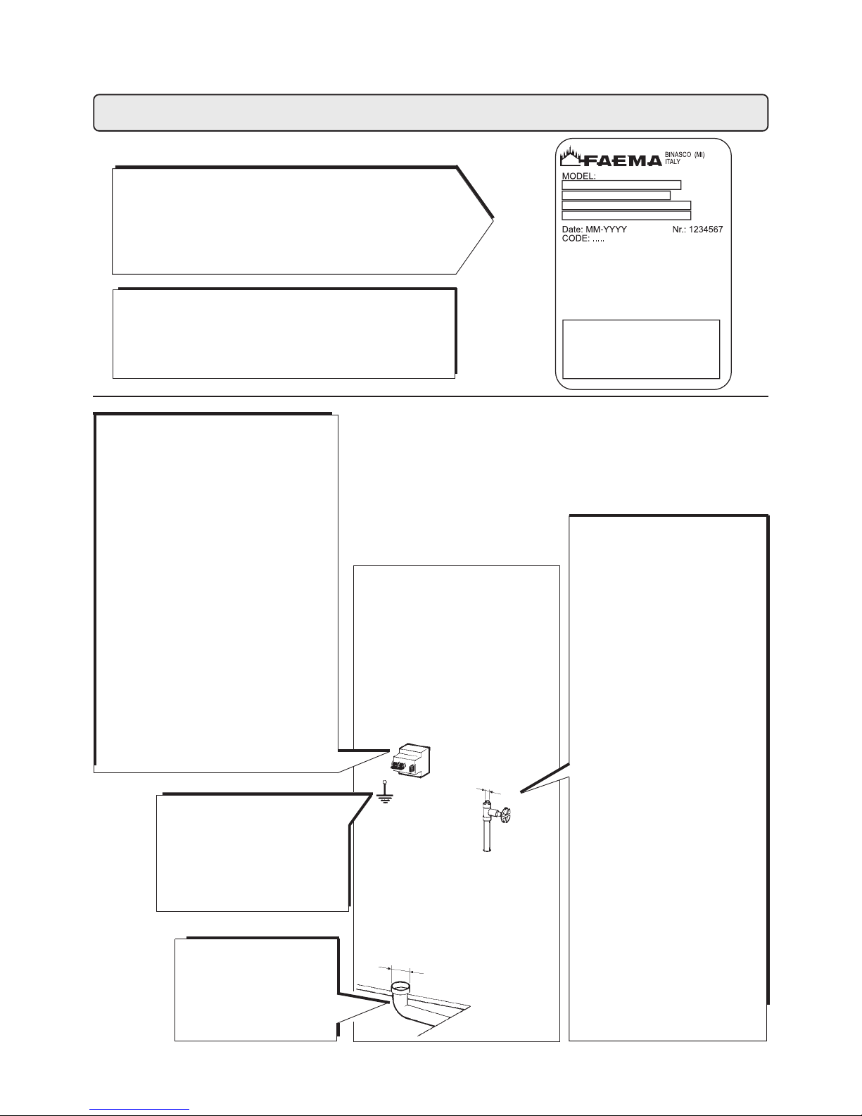
RUMOROSITA'
NOISE
BRUIT
GERÄUSCH
RUIDOSIDAD
RUIDO
L'apparecchio non supera i 70 dB
The equipment does not exceed 70dB
L'appareil ne depasse pas 70 dB
Das Gerät überschreitet 70 dB nicht
El aparato no supera los 70 dB
O aparelho não ultrapassa os 70 dB
Dati tecnici
Technical data
Données techniques
Technische Daten
Datos técnicos
Datos técnicos
Vedere la targa dati della macchina
See the machine's nameplate
Voir la plaque signalétique de la machine
Siehe Datenschild der Maschine
Ver la placa con los datos de la máquina
Ver a placa das características da
máquina
z IMPIANTO CLIENTE
z CONNECTIONS WHICH MUST BE
PREPARED BY THE CUST OMER
z BRANCHEMENTS, QUI DOIVENT
ÉTRE PRÉPARÉS PAR LE CLIENT
z VOM KUNDEN ZU ERSTELLENDE
ANSCHLÜSSE
z CONEXIONES, QUE DEBEN SER
PREPARADAS POR EL CLIENTE
z CONEXÕES QUE DEVEM SER
PREP ARADAS PELO CLIENTE
Min. Ø 50 mm.
Ø 3/8 GAS
SCARICO A PA VIMENTO
DRAIN
VIDANGE DU LOCAL
BODENABFLUSS
DESCARGA
DESCARGA
PRESSIONE MAX. RETE
WA TER MAINS MAX. PRESSURE
PRESSION MAX. EAU DE VILLE
MAX. DRUCK DER
WASSERLEITUNG
PRESION MAX. RED
PRESSÃO MAX. REDE
6 bar
(per pressioni più alte installare un
riduttore di pressione)
(for pressure beyond this value,
install a pressure reducer)
(pour pression plus haute installer
un deténdeur)
(bei höheren Druckwerten
Druckreduzierer erforderlich)
(para presiones más altas instalar
un reductor de presión)
(para pressões mais elevadas
instalar um redutor de pressão)
MESSA A TERRA: OBBLIGATORIA
GROUNDING: COMPULSORY
MISE A TERRE: OBLIGAT OIRE
ERDUNG: VORGESCHRIEBEN
PUESTA A TIERRA: OBLIGAT ORIA
INSTALAÇÃO DE TERRA:
OBRIGATORIA
INTERRUTTORE: Onnipolare con distanza di
apertura contatti 3 mm
Protezione da corrente di dispersione con
valore pari a 30 mA
SWITCH: Omnipolar switch with 3 mm
contact opening 30 mA dispersion-current
protection
INTERRUPTEUR: Omnipolaire, avec distance
d’ouverture des contacts égale à 3 mm
Protection contre la dispersion de courant
ayant une valeur égale à 30 mA
SCHALTER: Allpoliger Schalter mit
Kontaktöffnungsweite von 3 mm
Fehlerstromschutz für 30 mA
INTERRUPTOR: Omnipolar con distancia de
apertura contactos 3 mm
Proteccion contra corriente de dispersion
con valor de 30 mA
INTERRUPTOR: Omnipolar com uma
distância de abertura dos contatos de 3 mm
Protecção da corrente de dispersão com
valor igual a 30 mA
Rubinetto alimentazione acqua
Water feeding tap
Robinet alimentation eau
Wasserversorgungshahn
Torneira alimentação água
Torneira alimentação água
Page 13
13
Installazione - Installation - Installation - Installation - Instalación - Instalação
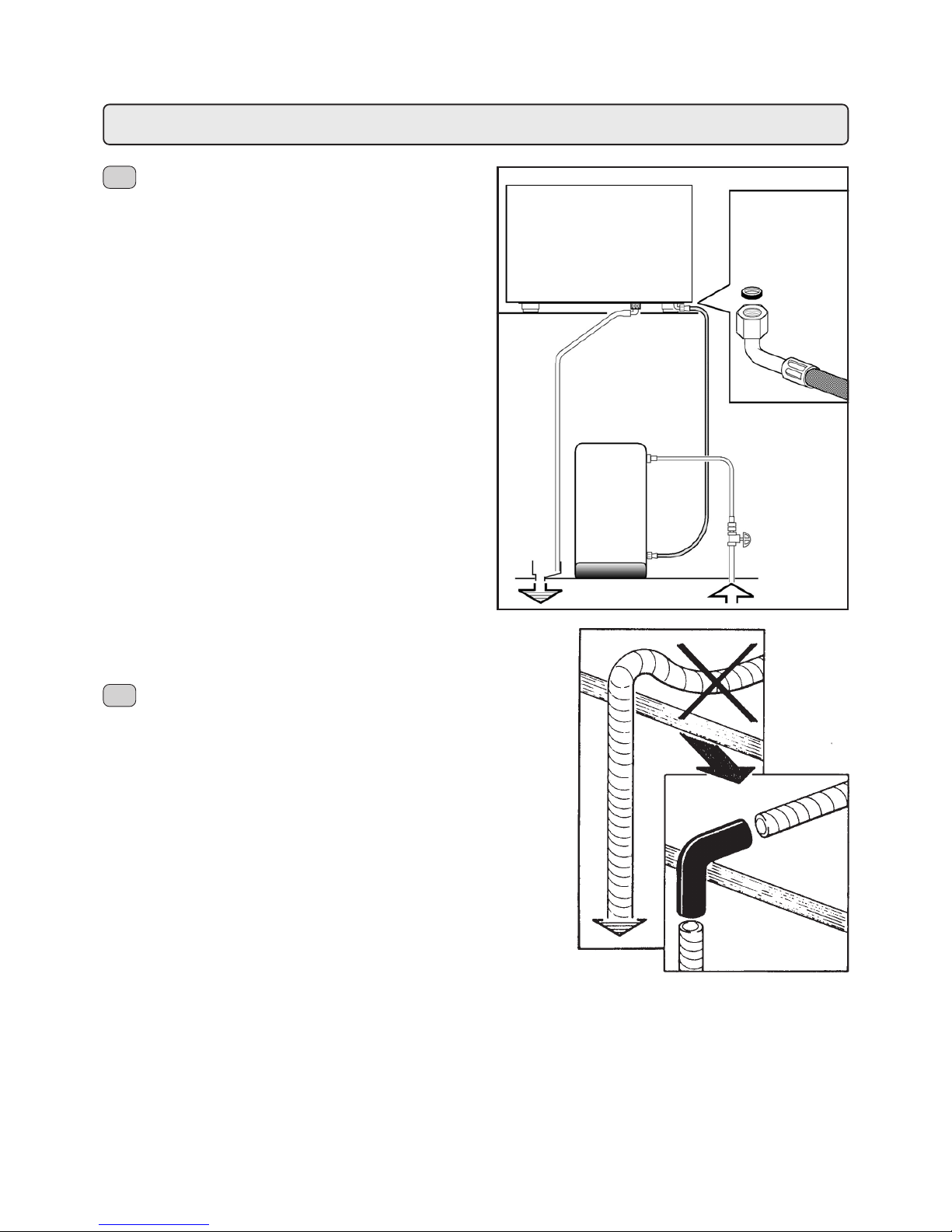
COLLEGAMENTI IDRAULICI
Posizionare l'apparecchio in perfetto piano orizzontale
agendo sui piedini, indi fissarli.
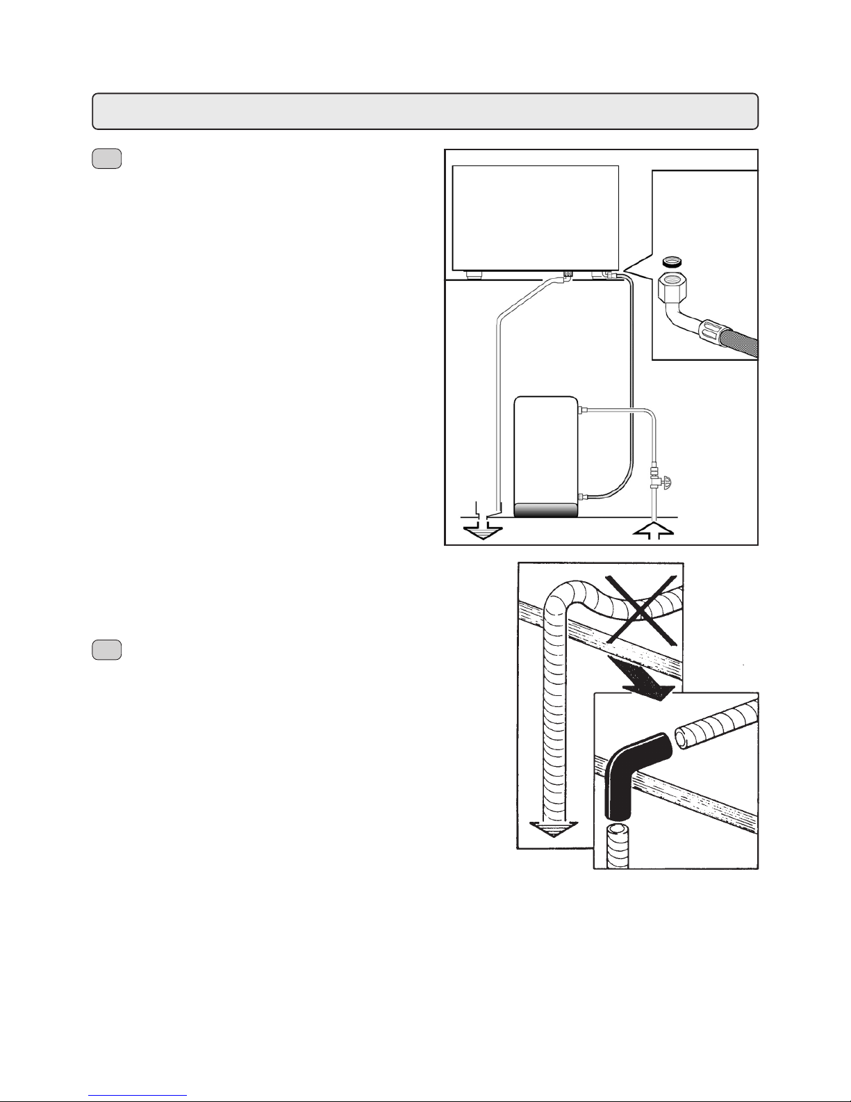
Eseguire i collegamenti idraulici come indicato in figura 1,
rispettando le vigenti norme di sicurezza idraulica del paese
di installazione.
Ricordarsi di interporre nelle giunzioni tra tubi e raccordi le
relative guarnizioni.
Se la durezza dell’acqua è superiore ai 8°F, si consiglia
l’installazione di un appropriato addolcitore ed eventualmente
di una valvola di non ritorno a monte dello stesso; per la
scelta attenersi alle norme locali vigenti in materia di igiene.
Nel caso si dovesse alimentare la macchina con acqua di
durezza superiore agli 8°F, per il buon funzionamento della
stessa, occorre applicare un piano di manutenzione specifico.
La quantità di cloro contenuta nell'acqua non deve superare
i 100 mg/l; in caso contrario provvedere all'installazione di
appropriati dispositivi.
N.B.: nel caso la pressione di rete possa salire oltre 6 bar,
prima dell'addolcitore installare un riduttore di pressione
tarato a 2÷3 bar.
Tubo di scarico: mettere un'estremità del tubo di scarico in
un pozzetto dotato di sifone per l'ispezione e la pulizia.
IMPORTANTE: il tubo di scarico, nelle curve, NON deve avere
un andamento come indicato in figura 2; in tal caso operare
come indicato in figura 3.
HYDRAULIC CONNECTION
Place the machine on a perfectly levelled surface, adjusting
and then fixing the feet in place.
Make the hydraulic connections as per Figure 1, in conformity
to the hidraulics safety laws in force in the country of
installation.
Remember to put the relevant washer in the junctions
between the tubes and the connectors.
If water hardness is higher than 8° F, it is advised to install a
water softener and, possibly, a non return valve before it. For
the choice, please comply with local hygiene laws.
If the machine is fed with water with a hardness of over 8° F,
a specific maintenance plan must be implemented to ensure
correct functioning of the machine.
The amount of chlorine in the water must not exceed 100
mg/l; otherwisw, install the appropriate devices.
N.B.: if the main pressure could rise above 6 bar, install a
pressure reducer calibrated at 2÷3 bar before the softener.
Drain tube: place one end of the drain tube into a tank with a
siphon for inspection and cleaning.
IMPORTANT: The disposal tube must NOT bend as in Figure
2. See Figure 3 for correct positioning.
I
GB
Fig. 1
MACCHINA
MACHINE
addolcitore
automatico
automatic
softener
Fig. 3
Fig. 2
Page 14
14
Installazione - Installation - Installation - Installation - Instalación - Instalação
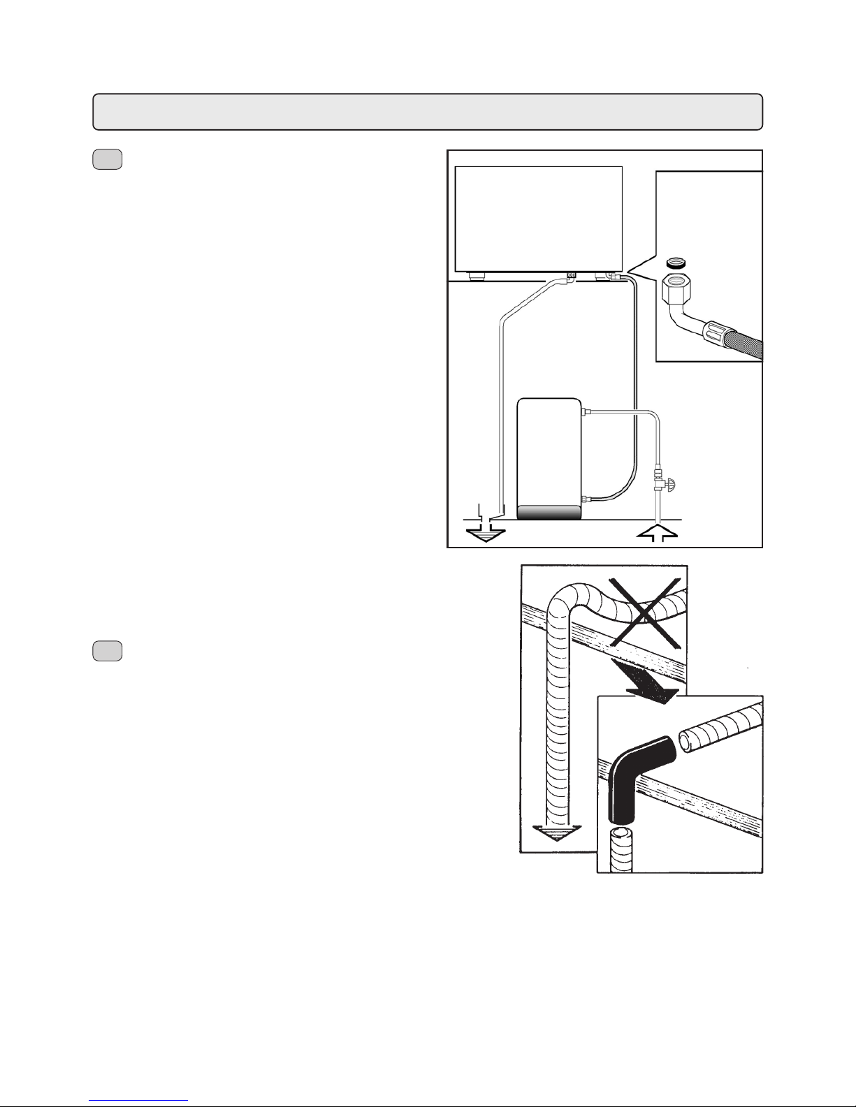
CONNECTION HYDRAULIQUE
Positionner l'appareil parfaitement horizontal en agissant
sur les pieds.
Faire les connections hydrauliques comme indiqué dans la
fig. 1, respectant les normes en vigueur de sécurité
hydraulique du pais d'installation.
Se rappeler d'interposer dans les jonctions entre tuyaux et
raccords les joints relatifs.
Si la dureté de l’eau est supérieure à 8°F, il est conseillé
d’installer un adoucisseur approprié et eventuellment d’un
clapet de non retour en amont de celui-ci; pour faire son
choix, se référer aux normes locales en vigueur en matière
d’hygiène.
Au cas où l’alimentation de la machine avec une eau de
dureté supérieure à 8°F serait nécessaire, pour le bon
fonctionnement de cette dernière, appliquer un plan
d’entretien spécifique.
La quantité de chlore contenue dans l'eau ne doit pas
dépasser 100 mg/l; en cas contraire veiller à l'installation de
dispositifs appropriés.
N.B.: dans les cas où la pression de réseau puisse monter
à plus de 6 bar installer , avant de l'adoucisseur, un réducteur
de pression taré à 2÷3 bar.
Tube de décharge: plaçer une extrémité du tube de décharge
dans une fosse dotée de syphon pour l’inspection et le
nettoyage.
IMPORTANT : dans les tournant s, le tube de décharge NE
DOIT PAS apparaitre comme sur la Fig. 2; dans ce cas,
procéder comme indiqué sur la Fig. 3.
WASSERANSCHLÜSSE
Die Maschine muß vollkommen waagerecht stehen (zu
diesem Zweck sind die entsprechend verstellbaren Füße zu
verwenden); dann sind die Füße mit den Sperrmuttern zu
sichern.
Die Wasseranschlüsse sind nach Abbildung 1 anzubringen,
unter Beachtung der am Aufstellungsort des Gerätes
geltenden einschlägigen Bestimmungen zur
Betriebssicherheit von hydraulischen Anlagen.
Es ist daran zu erinnern, dass Dichtungen zwischen Rohre
und entsprechende Anschlussstücke zu fügen sind.
Bei einer Wasserhärte über 8°F wird geraten, einen
Wasserenthärter sowie ggf. vor dem Wasserenthärter ein
Rückschlagventil zu installieren. Halten Sie sich bei der Wahl
des zu installierenden Systems an die am Aufstellungsort
der Maschine in Sachen der Hygiene geltenden
Bestimmungen.
Sollte die Maschine mit Wasser mit einer Härte über 8°F
versorgt werden müssen, so muß, um die vorschriftsmäßige
Funktion der Maschine zu gewährleisten, ein spezifischer
Wartungsplan eingehalten werden.
Der Chlorgehalt des Wassers darf 100 mg/l nicht
überschreiten; anderenfalls muß ein geeignetes Klärsystem
installiert werden.
ANMERKUNG: Falls der Netzwasserdruck über 6 bar steigen
könnte, ist vor dem Enthärter ein auf 2 bis 3 bar tarierter
Druckreduzierer zu installieren.
Ablaßschlauch: Positionieren Sie ein Ende des Schlauchs
in einem Ablauf, der mit Syphon zur Inspektion und Reinigung
ausgestattet sein muss.
WICHTIG: Der Ablaßschlauch darf nicht wie in Abb. 2 gezeigt
gekrümmt werden; setzen Sie bei Krümmungen ein
entsprechend gebogenes Rohr ein (Abb. 3).
F
D
Fig. 1
MACHINE
MASCHINE
adoucisseur
automatique
automatischer
Enthärter
Fig. 3
Fig. 2
Page 15
15
Installazione - Installation - Installation - Installation - Instalación - Instalação
LIGAÇÕES HIDRÁULICAS
Colocar o aparelho em perfeita posição horizontal regulando
mediante os pés e depois fixá-los.
Proceder às ligações hidráulicas tal como ilustrado na figura
1, respeitando as normas de seguranca hidráulica em vigor
no país de instalação.
Não esquecer de interpor nas ligações entre os tubos e os
acessórios as respectivas juntas.
Se a dureza da água for superior a 8°F, aconselha-se a
instalação de um adoçante apropriado e eventualmente de
uma válvula anti-regresso a colocar na parte superior do
mesmo; para a escolha respeitar as normas locais em vigor
em matéria de higiéne.
Caso se tenha de alimentar a máquina com água de dureza
superior aos 8°F, para um bom funcionamento da mesma,
é necessário aplicar um plano de manutenção específico.
A quantidade de cloro contida na água não pode ultrapassar
os 100 mg/l; em caso contrário proceder à instalação de
dispositivos específicos.
A quantidade de cloro existente na água não deve superar
os 100 mg/l; caso contrário proceder à instalação de
dispositivos apropriados.
N.B.: no caso em que a pressão de rede possa subir além
de 6 bar, antes do adoçador instalar um redutor de pressão
tarado a 2÷3 bar.
CONEXIONES HIDRAULICAS
Posicionar el aparato en un perfecto plano horizontal,
obrando sobre los piés, luego fijarlos.
Efectuar las conexiones hidràulicas según lo indicado en la
figura 1, respectando las vigentes normas de siguridad
hidráulica del país de instalación.
Acordarse de interponer las relativas ensambladuras en los
empalmes que unen los tubos a las conexiones.
Si la dureza del agua es superior a los 8°F, se aconseja la
instalación de un adecuado ablandador y eventualmente de
una válvula de retención antes del mismo; para la elección
hay que tener en cuenta las normas locales vigentes en
materia de higiene.
En el caso de que tuviese que alimentar la máquina con
agua que tenga una dureza superior a los 8°F, para el buen
funcionamiento de la misma, hay que aplicar un programa
de mantenimiento específico.
La cantidad de cloro contenida en el agua no tiene que
superar los 100 mg/l; en caso contrario, hay que instalar
adecuados dispositivos.
N.B.: si la presión de la red hidrica pudiese subir a más de
6 bar, instalar antes del adulcorador un reductor de presión,
calibrado a 2÷3 bar.
Tubo de desagüe: meter un extremo del tubo de desagüe en
un pozo equipado con sifón para la inspección y la limpieza.
IMPORTANTE: el tubo de desagüe, en las curvas, NO tiene
que tener un recorrido como se indica en la figura 2; en
dicho caso, realizar la operación descrita en la figura 3.
Tubo de descarga: colocar a extremidade do tubo de
descarga num poço dotado de sifão para a inspecção e a
limpeza.
IMPORTANTE: o tubo de descarga, nas curvas, NÃO deve
ter um desvio, conforme indicato na figura 2; neste caso
actuar conforme indicato na figura 3.
E
P
Fig. 1
MÁQUINA
MÁQUINA
adulcorador
automàtico
adoçador
automàtico
Fig. 3
Fig. 2
Page 16

16
Installazione - Installation - Installation - Installation - Instalación - Instalação
COLLEGAMENTO ELETTRICO
! Prima del collegamento verificare se l'impianto elettrico
predisposto a cura del Cliente rispetta le norme vigenti e
se ha la messa a terra regolamentare. Ricordiamo che il
Gruppo Cimbali Spa non risponde dei danni provocati da
un non corretto collegamento elettrico. Ricordiamo inoltre
la responsabilità dell'installatore nel caso di danni.
! Controllare inoltre:
- il tipo di collegamento indicato sulla etichetta posta sul
cavo di alimentazione
- la tensione deve corrispondere a quella indicata sulla
targa dati posta sul coperchio scatola.
! Le macchine sono predisposte per un collegamento:
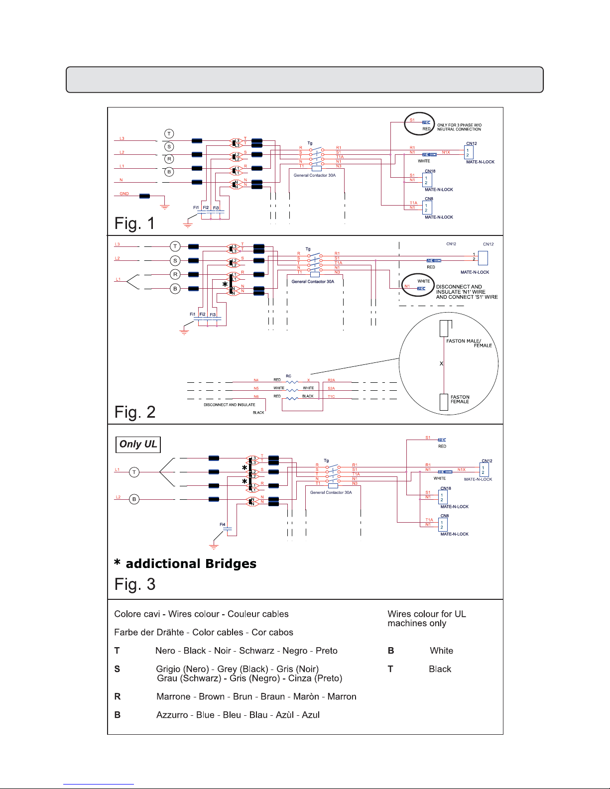
normalmente Y (fig. 1)
! Nel caso si debba modificare il collegamento da (Y) a (∆)
occorre intervenire seguendo gli schemi indicati in figura 2.
! Le macchine con collegamento monofase sono con
cablaggio specifico (vedi UL).
BRANCHEMENT ELECTRIQUE
! Avant de brancher, vérifier que l'installation électrique
prédisposée par le client respecte les normes en vigueur
et que la mise à terre soit règlementaire. Rappelons que
Gruppo Cimbali Spa ne répond pas des dommages
provoqués par un mauvais branchement électrique.
Rappelons en outre la responsabilité de l'installateur en
cas de dégâts.
! Contrôler également:
- le type de branchement indiqué sur l'étiquette apposée
sur le câble d'alimentation.
- la tension doit correspondre á celle qui est indiquée sur la
plaquette de données apposée sur le couvercle de la boîte.
! Les machines sont prédisposées pour un branchement:
normalement Y.
! Au cas où une modification du raccordement monophase
de (Y) avec (∆) serait nécessaire, intervenir en suivant les
schémas indiqués dans la figure 2.
! Les machines à raccordement monophase sont dotées
d’un câblage spécifique (voir UL).
ELECTRIC CONNECTION
! Before making the connection, verify that the electric wiring
prepared by the customer follows the current regulations and
that it has been earted according to regulations. Remember
that Gruppo Cimbali Spa is not responsible for damages
due to incorrect electrical connections and, furthermore, that
the installer is responsible in case of damage.
! Besides the above, check:
- the type of connection indicated on the label found on the
power cable.
- that the voltage corresponds to that indicated on the
nameplate data found on the box cover.
! The machines are planned for these connections: normally
Y (fig. 1).
! If the connection between (Y) and (∆) needs to be
changed, follow the instructions in the diagrams in
Figure 2.
! The machines with single phase connection have a
special wiring system (see UL).
I
GB
F
STROMANSCHLUSS
! Überprüfen Sie vor der Erstellung des Stromanschlusses, ob
die vom Kunden vorbereitete Elektroanlage den einschlägigen
Bestimmungen entspricht und über eine vorschriftsmäßige
Erdung verfügt. Wir weisen erneut darauf hin, daß die Firma
Gruppo Cimbali Spa keinerlei Haf tung für Schäden übernimmt,
die durch eine unsachgemäße Elektroanlage verursacht
werden. Wir erinnern außerdem an die Haftbarkeit des
Installateurs für eventuell enstehende Schäden.
! Ferner folgendes kontrollieren:
- die am Stromkabel angegebene Anschlußart
- ob die Netzspannung mit den Angaben des T ypenschilds
übereinstimmt, das auf dem Gehäusedeckel des Geräts
angebracht ist.
! Die Geräte sind für folgende Anschlußarten vorgesehen:
Normalerweise Stern-Verbindung ( Y ).
! Gehen Sie zur Modifikation der Verbindung zwischen (Y)
und (∆) wie in der Abbildung 2 dargestellt vor.
! Die Maschinen mit einphasigem Anschluß haben eine
spezifische Verdrahtung (siehe UL).
D
LIGAÇÃO ELÉCTRICA
! Antes da ligação verificar se o equipamento eléctrico
preparado pelo Cliente respeita as normas em vigor e
tem a instalação à terra regulamentar. Recordamos que o
Gruppo Cimbali Spa não responde pelos danos
provocados por uma ligação eléctrica
! Verificar ainda:
- el tipo de conexión indicado en la etiqueta situada en el
cable de alimentación.
- a tensão deve corresponder àquela indicada sobre a
placa dos dados colocada sobre a tampa da caixa.
! As máquinas são preparadas para uma ligação:
geralmente Y (fig. 1).
! No caso de se ter que modificar a ligação de (Y) para (∆) é
necessário intervir seguindo os esquemas indicados na
figura 2.
! As máquinas com ligação mono-fásica têm uma
cablagem específica. (ver UL).
CONEXION ELECTRICA
! Antes de conectarse, verificar si la instalación eléctrica
efectuada por el cliente está conforme con las normas
vigentes y si la puesta a tierra es regulamentar. Hacemos
presente que el Gruppo Cimbali Spa no responde de los
daños causados por una instalación électrica defectuosa.
Recordamos además la responsabilidad del instalador,
en el caso de que se verificasen daños.
! Además hay que controlar:
- o tipo de ligação indicado na etiqueta colocada sobre o
cabo de alimentação
- la tensión tiene que corresponder a la indicada en la
placa con los datos situada sobre la tapa del contenidor.
! Las máquinas están ya predispuestas para las siguientes
conexiónes: normalmente Y.
! En el caso de que se tenga que modificar la conexión de
(Y) a (∆), hay que intervenir siguiendo los esquemas
indicados en la figura 2.
! Las máquinas con conexión monofásica tienen un
cableado específico (véase UL).
E P
Page 17
17
Installazione - Installation - Installation - Installation - Instalación - Instalação
Page 18
18
Installazione - Installation - Installation - Installation - Instalación - Instalação
LIGAÇÃO EQÜIPOTENCIAL
Este aparelho está equipado com um borne, colocado
sob a sua base, para a ligação a um condutor externo
eqüipotencial.
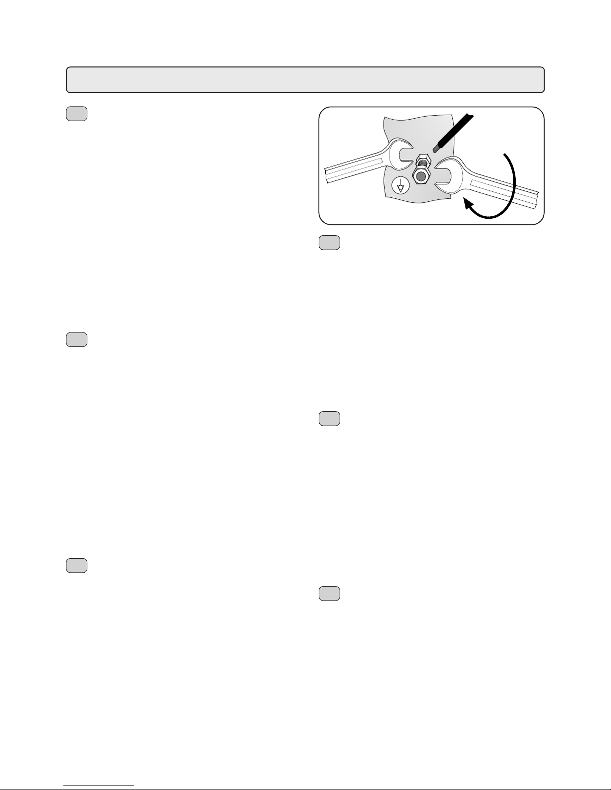
Uma vez terminada a instalação é NECESSÁRIO efectuar
este tipo de ligação:
- usar um condutor com uma secção nominal em
conformidade com as normas vigentes;
- ligar o borne, ver a figura.
A falta de cumprimento desta norma de segurança alivia o
fabricante de qualquer responsabilidade por avarias ou
danos que poderiam ser causados a pessoas ou bens.
NOTA: NÃO LIGAR À LIGAÇÃO DE TERRA DA INST ALAÇÃO
DE DISTRIBUIÇÃO ELÉCTRICA ENQUANTO O CONDUTOR
DE LIGAÇÃO DE TERRA NÃO É CONSIDERADO UM
CONDUTOR DE LIGAÇÃO EQÜIPOTENCIAL.
STROMANSCHLUSS MIT POTENTIALAUSGLEICH
Dieses Gerät ist unter dem Untergestell mit einer
Anschlußklemme versehen, die mit einem externen
Stromausgleichsleiter zu verbinden ist.
Nach der Installation MUSS der Stromanschluß wie folgt
vorgenommen werden:
- Einen Leiter verwenden, dessen Nennquerschnitt den
einschlägigen Unfallschutzbestimmungen entspricht;
- ihn wie in der Abbildung gezeigt an die Klemme
anschließen.
Bei Nichtbeachtung dieses Sicherheitshinweises schließt
der Hersteller jedwede Haftungsansprüche für Personenoder Sachschäden aus.
HINWEIS: NICHT AN DIE ERDUNG DER
STROMZUFUHRANLAGE ANSCHLIESSEN, DA DER
ERDUNGSLEITER EINES SPEISUNGSKABELS NICHT ALS
AUSGLEICHSLEITER GEL TEN KANN.
CONEXION EQUIPOTENCIAL
Este aparato está preajustado con un borne ubicado
debajo de la base para la conexión de un conductor externo
equipotencial.
Una vez terminada la instalación es NECESARIO efectuar
este tipo de conexión:
- usar un conductor con una sección nominal conforme con
las normas vigentes.
- conectar al borne (ver figura).
La falta de respeto de esta norma de seguridad exime al
fabricante de toda responsabilidad por desperfectos o daños
que puedan ser causados a personas o cosas.
NOTA: NO CONECTAR CON LA PUESTA A TIERRA DE LA
INST ALACION DE DISTRIBUCION ELECTRICA DADO QUE EL
CONDUCTOR DE PUESTA A TIERRA EN UN CABLE DE
ALIMENTACION NO ES CONSIDERADO UN CONDUCT OR DE
CONEXION EQUIPOTENCIAL.
POTENTIAL-EQUALIZING CONNECTION
This connection, which is the one called for by several
norms, avoids electrical potential differences building up
between any equipment that may be installed in the same room.
There is a terminal clip on the under side of the base of the
machine to which an external potential-equalizing wire should
be connected.
This connection is ABSOLUTELY NECESSARY and must be
made right after the machine is installed.
- Use a wire whose cross-sectional area conforms to the
existing norms.
- Make the terminal connection (see diagram) and then
connect the other end to the ground connections located
on the adjacent equipment.
Failure to do observe these safety precautions will exempt the
manufacturer from any responsibility as regards damage
caused to persons or property.
NOTE: DO NOT CONNECT THE MACHINE’S TERMINAL CLIP TO
THE MAINS GROUND TERMINAL BECAUSE THE GROUND
TERMINAL OF ANY MAIN SOURCE OF ELECTRICAL POWER IS
NOT CONSIDERED TO BE A POTENTIAL-EQUALIZING
CONNECTION.
CONNEXION EQUIPOTENTIELLE
Ce raccordement, prévu par certaines normes, permet
d'éviter les différences de niveau de potentiel électrique entre
les masses des appareils installés dans une même pièce.
Cet appareil poss de sous sa base d’une borne servant pour
la connexion d’un conducteur externe équipotentiel.
Une fois terminée l’installation, il est NECESSAIRE d’effectuer
ce type de connexion:
- utiliser un conducteur ayant une section nominale
conforme aux normes en vigueur;
- relier à la borne (voir figure) et l'autre extrémité aux masses
des appareils adjacents.
Le non-respect de cette norme de sécurité libère le fabricant
de toute responsabilité en cas de panne ou de dommages
causés aux personnes ou aux choses.
N.B.: NE PAS RELIER A LA TERRE DE L’INST ALLA TION DE
DISTRIBUTION ELECTRIQUE CAR LE CONDUCTEUR DE TERRE
D’UN CABLE D’ALIMENTA TION N’EST PAS CONSIDERE COMME
ETANT UN CONDUCTEUR DE CONNEXION EQUIPOTENTIEL.
I
GB
COLLEGAMENTO EQUIPOTENZIALE
Questo collegamento previsto da alcune norme, ha la
funzione di evitare le differenze di livello di potenziale elettrico,
tra le masse delle apparecchiature installate nello stesso
locale.
Questo apparecchio è predisposto con un morsetto posto
sotto il basamento per il collegamento di un conduttore esterno
equipotenziale.
T erminata l'inst allazione è NECESSARIO eseguire questo tipo
di collegamento:
- usare un conduttore avente una sezione nominale in
conformità con le norme vigenti.
- collegare al morsetto (vedi figura) e l'altro capo alle masse
delle apparecchiature adiacenti.
La mancata attuazione di questa norma di sicurezza scagiona
il costruttore da ogni responsabilità per guasti o danni che
possano essere causati a persone o cose.
N.B. NON COLLEGARE ALLA MESSA A TERRA DELL'IMPIANTO
DI DISTRIBUZIONE ELETTRICA IN QUANTO IL CONDUTTORE
DI MESSA A TERRA IN UN CA VO DI ALIMENT AZIONE NON
VIENE CONSIDERAT O UN CONDUTTORE DI COLLEGAMENTO
EQUIPOTENZIALE.
F
D
E
P
Page 19
19
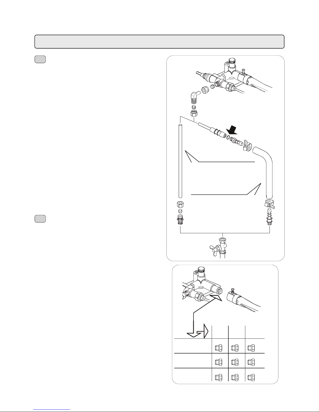
COLLEGAMENTO DEL GAS
(solo per modelli con + GAS)
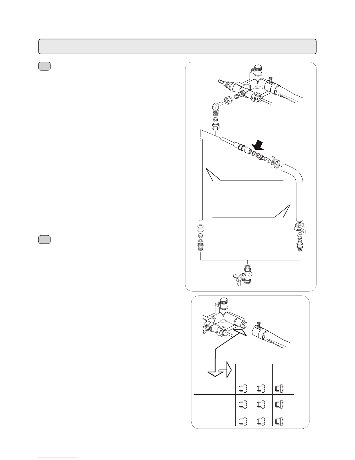
Tenendo presente i regolamenti locali, il collegamento alla
tubazione del gas può essere fatto sia con tubo rigido che
con tubo flessibile vedi figura.
Per l'installazione con tubo flessibile:
- In dotazione vengono forniti 2 raccordi portagomma per
favorire il montaggio di tubi, rispondenti alle normative di
sicurezza, con diverse dimensioni, in funzione del tipo di
gas utilizzato.
- Bloccare il tubo sui raccordi portagomma con fascette
rispondenti alle normative di sicurezza.
Una volta effettuato il collegamento, verificare e individuare
le eventuali fughe con soluzione saponosa ed eliminarle;
rammentiamo le responsabilità dell'installatore nel caso di
imperfetto funzionamento dell'impianto.
Sostituzione iniettori
La macchina è predisposta per l'alimentazione con GPL (gas
liquido) ossia ha l'iniettore e l'autoregolatore montato e tarato
in fabbrica per tale tipo di gas. Se il gas è di tipo diverso,
occorre cambiare l'iniettore " A " montato con quello adatto;
- sganciare la molletta blocca bruciatore.
- far scorrere il bruciatore dopo aver allentato la vite " B ".
- sostituire l'iniettore con quello adatto vedere tabella.
- riposizionare il tutto ricordandosi di riagganciare la molletta
blocca bruciatore.
GAS CONNECTION
(only for models with + GAS)
Keeping local regulations in mind, the connection to gas
tubig can be done with either a rigid tube or a flexible tube,
see Figure.
For installation with flexible tube:
- Two hose-adaptor connectors, with differing dimensions
according to the type of gas used, are supplied for the
installation of the tube. The connectors conform to safety
norms.
- Block the tube on the hose-adapter connectors with clamps
that conform to the safety norms.
Once the connection is made, check for possible gas leaks
with a soapy solution and eliminate them. We remind you
that any improper functioning of the installation is the
responsibility of the installer.
Substitute injectors
The machine is prepared for the use of GPL (liquid propane
gas), that is, it has an injector and self-adjuster installed and
calibrated in the factory for that type of gas. If the gas is of a
different type, the injector " A " must be replaced with a suitable
injector;
- disconnect the burner block spring.
- let the burner slide after having loosened screw " B ".
- replace the injector with the suitable one. See table.
- reposition the parts, remembering to reconnect the burner
block spring.
I
Collegamento con tubo rigido in rame ricotto
Connection with rigid annesied copper pipe
GB
Collegamento con tubo flessibile per gas
Connection with gas hose
2
34
gruppi
units
gruppi
units
gruppi
units
GAS LIQUIDO
LIQUID GAS
GAS METANO
METHANE GAS
GAS CITTÀ
TOWN GAS
70 80 90
100 120 140
160 190 220
Installazione - Installation - Installation - Installation - Instalación - Instalação
Page 20
20
Installazione - Installation - Installation - Installation - Instalación - Instalação
BRANCHEMENT DU GAZ
(seulement pour modèles avec + GAS )
Dans le respect des règlementations locales, le branchement
aux conduites de gaz peut se faire aussi bien avec un tuyau
rigide qu'avec un tuyau flexible (voir figure).
Pour l'installation avec un tuyau flexible:
- 2 raccords porte-caoutchouc sont livrés en dotation pour
faciliter le montage de tuyaux, répondant aux normes de
sécurité, avec différentes dimensions, en fonction du type
de gaz utilisé.
- Bloquer le tuyau sur les raccords porte-caoutchouc avec
des colliers aux normes de sécurité.
Une fois le branchement effectué, vérifier et déceler les fuites
éventuelles avec une solution savonneuse, et les éliminer;
nous rappelons la responsabilité de l'installateur en cas de
fonctionnement imparfait de l'installation.
Remplacement injecteurs
La machine est prédisposée pour l'alimentation au GPL (gaz
liquide), c'est-à-dire que l'injecteur et l'autorégulateur sont
montés et tarés en usine pour ce type de gaz. Si le gaz est
d'un autre type, il faut remplacer l'injecteur déjà monté par
celui qui convient;
- détacher la pince qui bloque le brûleur.
- faire coulisser le brûleur après avoir dévisser la vis " B ".
- remplacer l'injecteur par celui qui est adapté (voir tableau).
- repositionner le tout sans oublier de raccrocher la pince
qui bloque le brûleur.
GASANSCHLUSS
( ausschl. für modelle + GAS )
Je nach örtlich geltenden Bestimmungen kann für den
Anschluß an die Gasleitung sowohl ein Rohr als auch ein
Schlauch verwendet werden (siehe Abbildung).
- Unter den mitgelieferten Extrateilen befinden sich 2
Schlauchhalterungsanschlüsse zur leichteren Anbringung
der Schläuche, die den Sicherheitsbestimmungen
entsprechen und in zwei verschiedenen Größen ausgeführt
sind (auszuwählen je nach gegebener Gasart).
- Den Schlauch an den Schlauchhalterungsanschlüssen
mit Schlauchschellen sichern, die den
Sicherheitsbestimmungen entsprechen.
Nach Erstellung des Gasanschlusses die Leitungen mit Hilfe
einer Seifenlösung auf Austritte überprüfen und
gegebenenfalls beseitigen. Wir erinnern, daß für eine
unsachgemäße Funktionstüchtigkeit der Anlage der
Installateur haftbar gemacht wird
Ersetzung der Einspritzventile
Das Gerät ist vorbereitet für die Versorgung mit GPL-Gas
(Flüssiggas), d.h. das Einspritz- und das Selbstregelventil
sind im Werk für diese Gasart ausgewählt und tariert worden.
Sollte das Gerät mit einer anderen Gasart versorgt werden,
ist das eingebaute Einspritzventil " A " mit dem jeweils
erforderlichen zu ersetzen;
- Die Sperrfeder des Brenners aushaken.
- nach Lockern der Schraube " B " den Brenner
wegschieben.
- das Einspritzventil mit dem geeigneten Ventil ersetzen
(siehe Tabelle).
- alle T eile in ihre vorherige Position zurückbringen und auch
die Sperrfeder des Brenners wieder einhaken.
F
Branchement rigide avec tuyau en culvre recuit
Verbindung mit festem Höhr sus gegrühiem Kupfor
D
Branchement avec durite pour gaz
Verbindung mit Gasschlauch
2
34
groupes
gruppen
groupes
gruppen
groupes
gruppen
GAZ LIQUIDE
FLUESSIGGAS
GAZ METHANE
METHANGAS
GAZ DE VILLE
STADTGAS
70 80 90
100 120 140
160 190 220
Page 21
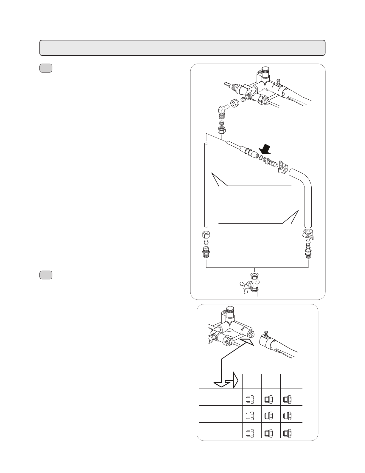
21
Installazione - Installation - Installation - Installation - Instalación - Instalação
CONEXION DEL GAS
( solo para modelos con + GAS )
Tomado en consideración los reglamentos locales, la
conexión con la tuberia del gas se puede efectuar sea con
un tubo rigido, que con un tubo flexible, ver figura. Para la
instalación con tubo flexible:
- En dotación se suministran dos empalmes portagoma
que favorecen la instalación de las tuberías, conformes a
las normativas de seguridad, con diferentes dimensiones,
en función del tipo de gas utilizado.
- Bloquear el tubo sobre los empalmes portagoma con
sbrazaderas conformes a las normativas de seguridad.
Una vez que se haya efectuado la conexión, verificar e
individuar eventuales fugas con solución jabonosa y
eliminarlas; nos permitimo recordar la responsabilidad del
instalador en el caso de funcionamento defectuoso de la
instalación.
Sustitucion de los inyectores
La máquina estápredispuesta para su alimentación con GPL
(gas liquido), o sea tiene el inyector y el autoregulador y
calibrados en fábrica para dicho tipo de gas.
Si a caso el gas fuera diferente, es necesario cambiar el
inyector " A " instalado, con otro idóneo:
- desenganchar la pinza que bloquea el quemador.
- hacer resbalar el quemador después de haber aflojado el
tornillo " B ".
- substituir el inyector con el fabricado adrede (ver
prospecto).
- posicionar de nuevo todas las piezas acordandose de
enganchar nuevamente le abrazadera que bloquea el
quemador.
LIGAÇÃO DO GÁS
(apenas para modelos con + GAS)
Respeitando as normas internacionais de segurança, a
ligação do gás pode ser feita quer com tubo rigido quer com
tubo flexível (ver figura).
No caso de instalação com tubo flexível:
- Em dotação são fornecidos 2 ligações para borracha a
fim de favorecer a mon tagem de tubos, as quais
correspondem às normas de segurança com diversas
dimensões, em função do tipo de gas utilizado.
- Fixar o tubo nas ligações de borracha usando braçadeiras
com parafuso correspondentes às normas de segurança.
Uma vez que a ligação foi efectuada, verificar e controlar
eventuais fugas de gás mediante o uso de água e sabão e
eliminá-las; lembramos que no caso de imperfeito
funcionamento a responsabilidade é do instalador.
Substituição dos injectores
A máquina encontra-se predisposta para funcionar com GPL
(gás liquido) ou seja, tem o injector e o auto-regulador
montados e regulados na fábrica para tal tipo de gás.
Se o gás é diferente é necessário mudar o injector " A " que
se encontra montado, com aquele apropriado:
- desprender a mola de bloqueagem do queimador.
- retirar o queimador depois de ter desapertado o parafuso
" B ".
- substituir o injector com aquele apropriado (ver tabela).
- montar tudo de novo não se esquecendo de montar a
mola de bloqueagem do queimador.
E
Conexión con tubo rigido en cobre reconcido
Ligação com tubo rigido em cobre recondido
P
Conexión con manguera para gas
Ligação com tubo flexivel para gas
2
34
grupos
grupos
grupos
grupos
grupos
grupos
GAS LÍQUIDO
GÁS LÍQUIDO
GAS METANO
GÁS METANO
GAS DE CIUDAD
GÁS DA CIDADE
70 80 90
100 120 140
160 190 220
Page 22
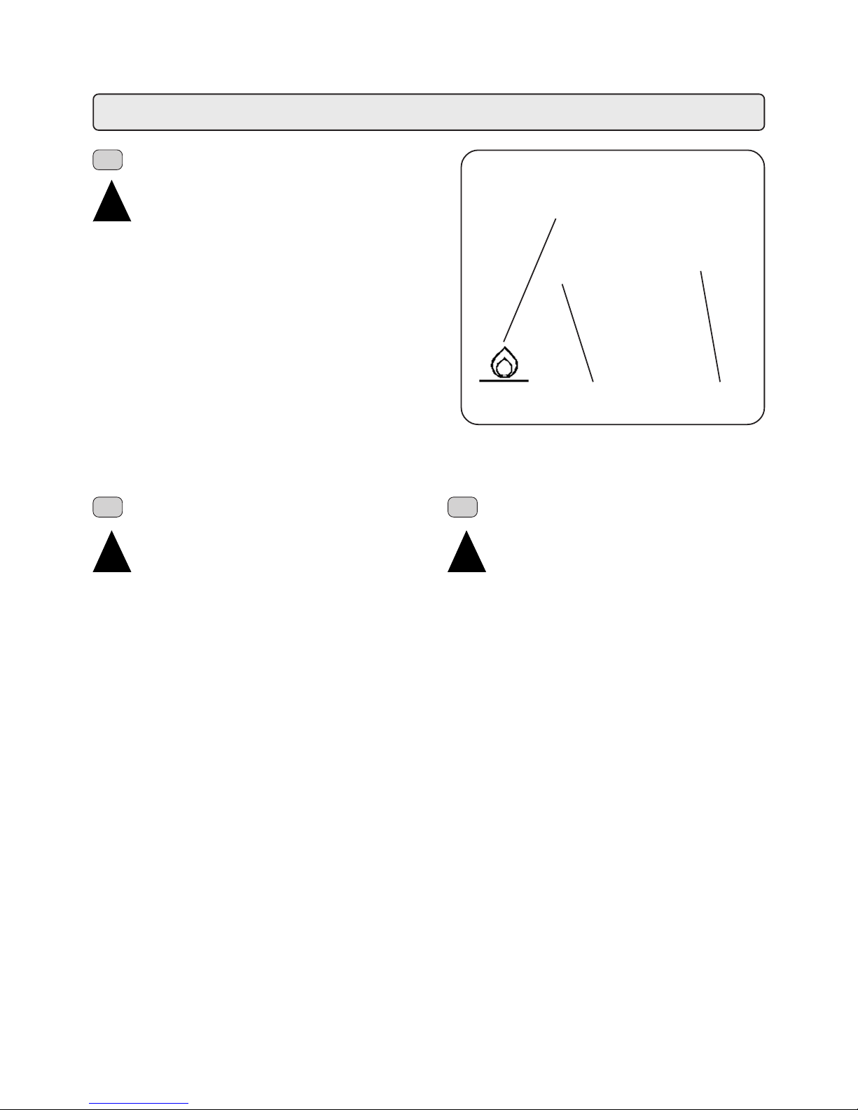
22
ELECTRONIC GAS LIGHTING
(only for models with + GAS)
“Do not light the gas when the boiler is under
pressure”.
Before switching on the machine, check that:
- The Mains electric switch is on.
- The water tap is open.
- The gas tap is open.
Press and rotate the knob of tap 24 towards the left to position
B, and keep pressed for about 30 seconds. Check that
window (23) is open and after a few seconds release knob
24.
The boiler is heating up. Wait until the indication on the display
(14) corresponds to the pressure value required.
At the end of the working day, switch of f the machine by rotating
the general switch (1) to the 0 position and turn of the gas tap
(24) turning it to the “0” position.
ALLUMAGE ELECTRONIQUE DU GAZ
(seulement pour modèles avec + GAS)
"Ne pas allumer le gaz quand la chaudière est
sous pression".
Avant de mettre en service la machine, contrôler que:
- s'assurer que l'interrupteur général de l'alimentation
électrique est bien enclenché;
- le robinet principal e l'alimentation hydrique est ouvert;
- le robinet d'étranglement sur le réseau de gaz est ouvert.
Appuyer et tourner vers la gauche la poignée du robinet (24)
sur la position B en la maintenant appuyée pendant 30"
environ; contrôler que la lucarne (23) est bien en marche et
après quelques secondes relâcher la poignée (24) .
Le chauffage de la chaudière est en marche et il faut attendre
que l'indication affichée sur l'écran (14) corresponde à la
valeur de pression prévue pour le fonctionnement de la
machine.
Au terme de l'activité journalière, éteindre la machine en
tournant l'interrupteur général (1) jusqu'à la position 0 et
fermer le robinet du gaz (24) en le remettant sur la position "0".
ACCENSIONE ELETTRONICA DEL GAS
(solo per modelli con + GAS)
"Non accendere il gas quando la caldaia è in
pressione".
Prima di mettere in funzione la macchina controllare che:
- l'interruttore generale dell'alimentazione elettrica sia
inserito;
- il rubinetto principale dell'alimentazione idrica sia aperto;
- il rubinetto di intercettazione sulla rete gas sia aperto.
Premere e ruotare verso sinistra la manopola del rubinetto
24 sulla posizione B mantenendola premuta per circa 30";
controllare l'avvenuta accensione dalla finestrella (23) e dopo
alcuni secondi rilasciare la manopola 24.
Il riscaldamento della caldaia è in funzione, ed occorre
attendere che l'indicazione sul display (14) corrisponda al
valore di pressione previsto per l'esercizio.
Al termine dell'attività giornaliera, spegnere la macchina
premendo l'interruttore generale (1) e chiudere il rubinetto del
gas (24) riportandolo sulla posizione "0".
24
1
B
Installazione - Installation - Installation - Installation - Instalación - Instalação
!!
!!
!
I
GB F
!!
!!
!
!!
!!
!
Page 23
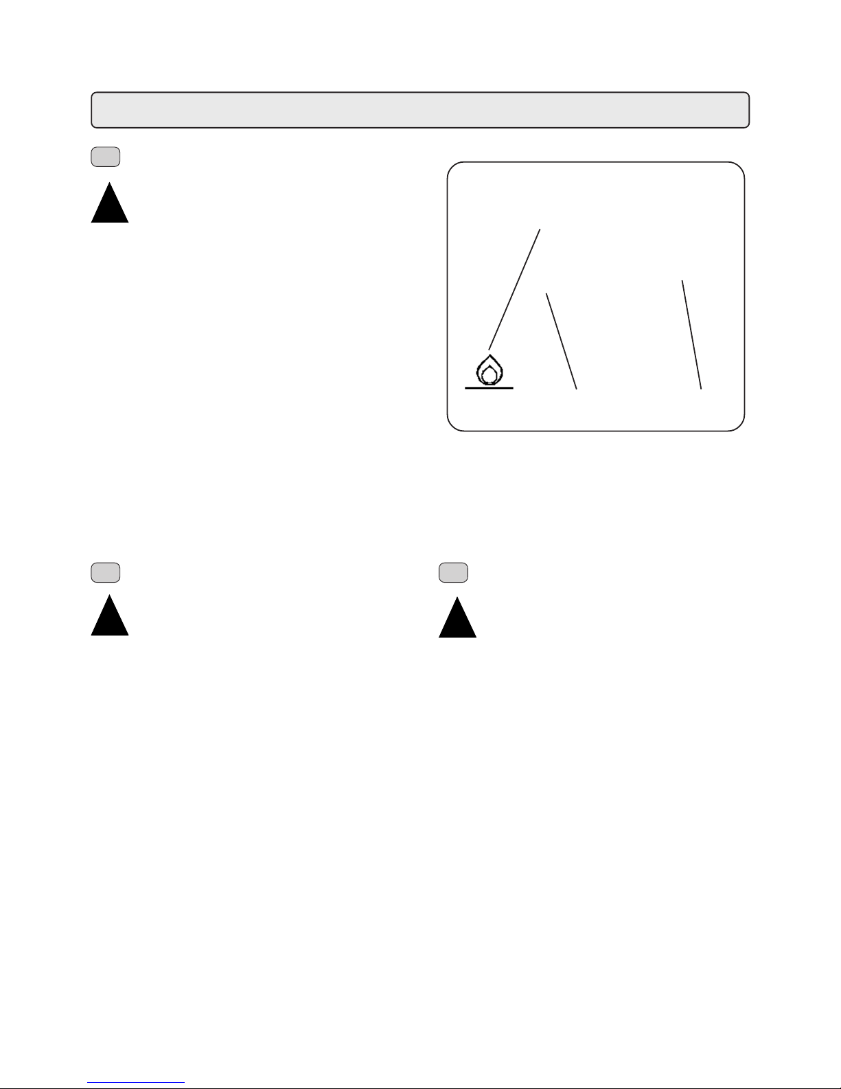
23
ELEKTRONISCHES ANSCHAL TEN DES GASES
(ausschl. für modelle + GAS)
"Das Gas darf nicht gezündet werden, wenn der
Heizkessel unter Druck steht!"
Kontrollieren Sie vor Einschaltung der Maschine folgende
Punkte:
- der Hauptschalter zur Stromversorgung muß eingeschaltet
sein;
- der Haupthahn zur Wasserversorgung muß geöffnet sein;
- der Hahn zur Absperrung des Gaskreises muß geöffnet
sein.
Drehen Sie den Regler des Hahns 24 auf die Position B, und
halten Sie ihn in dieser Stellung etwa 30 Sekunden lang
gedrückt; vergewissern Sie sich von der erfolgten Zündung,
indem Sie durch das Sichtfenster (23) schauen, und lassen
Sie den Regler des Hahns (24) nach einigen Sekunden
wieder los.
Der Kessel wird nun beheizt, und Sie müssen abwarten, bis
auf dem Display (14) der vorgeschriebene Betriebsdruck
angezeigt wird.
Nach dem täglichen Betrieb muß die Maschine ausgeschaltet
werden, indem Sie den Hauptschalter (1) auf die Position „0"
stellen und den Gashahn (24) schließen, indem Sie ihn
ebenfalls auf die Position „0" stellen.
24
1
B
ENCENDIDO ELECTRÓNICO DEL GAS
(solo para modelos con + GAS)
“No encienda el gas cuando la caldera esté bajo
presión”
Antes de poner en funcionamiento la máquina, controle que:
- el interruptor general de la alimentación eléctrica esté
conectado;
- el interruptor principal de la alimentación hídrica esté
abierto;
- la válvula de cierre en la red del gas esté abierto.
Presione y gire hacia la izquierda la manivela de la válvula
(24) hasta llegar a la posición B, manteniéndola presionada
unos 30”; controle que se haya encendido la ventanilla (23)
y después de unos segundos deje de presionar la manivela
(24).
El calentamiento de la caldera está en funcionamiento y hay
que esperar a que la indicación en el display (14)
corresponda con el valor de presión previsto para el ejercicio.
Al final del trabajo de cada día, apague la máquina girando
el interruptor general (1) hasta la posición 0 y cierre la válvula
del gas (24) volviéndolo a colocar en la posición “0”.
ACENDIMENTO ELECTRÓNICO DO GÁS
(só para os modelos com + GÁS)
"Não acender o gás quando a caldeira se encontra
em pressão"
Antes de colocar a máquina em função verificar que:
- interruptor geral da alimentação eléctrica seja inserido;
- a torneira principal da alimentação hídrica esteja aberta;
- a torneira de intercepção sobre a rede gás esteja aberta.
Carregar e rodear o manípulo da torneira A para a esquerda
em posição B, mantendo-o carregado durante cerca de 30",
verificar a ocorrência do acendimento através da janelinha
(23) e após alguns segundos abandonar o manípulo A.
Aquecimento da caldeira encontra-se em função e é
necessário aguardar que a indicação no mostrador (78)
corresponda ao valor de pressão previstos para o exercício.
No fim da actividade diária desligar a máquina carregando no
interruptor geral (1) e fechar a torneira do gás (24) recolocandoo sobre a posição "0".
Installazione - Installation - Installation - Installation - Instalación - Instalação
D
E P
!!
!!
!
!!
!!
!
!!
!!
!
Page 24
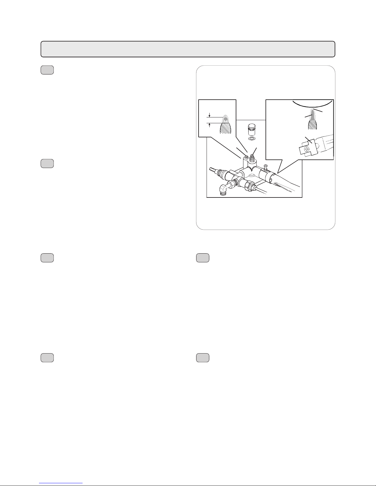
24
Installazione - Installation - Installation - Installation - Instalación - Instalação
CONNECTION TO GAS HEA TING
(only for models with + GAS)
Adjustment of the combustion
- The flame must be blue. It should not be detached from
the burner and should not be yellowish around the edges.
- Position the air lock C at the right moment.
- For the height of the flame see figure 1.
Adjustment of the flame in operation
- Adjust screw D.
- The calibration must be less than that imposed for the
pressurestat.
Adjustment of the operating minimum
- Adjust screw E.
- The height of the flame must be as shown in figure 2.
IMPIANTO DI RISCALDAMENTO A GAS
(solo per modelli con + GAS)
Regolazione della combustione
- La fiamma si deve presentare di colore azzurro, non deve
staccarsi dal bruciatore e non deve avere bordi giallognoli.
- Posizionare opportunamente la serranda aria “C”.
- Altezza della fiamma vedere figura 1.
Regolazione della fiamma in esercizio
- Agire sulla vite “D”.
- La taratura deve essere inferiore a quella impostata per il
pressostato.
Regolazione del minimo di esercizio
- Agire sulla vite “E”.
- L’altezza della fiamma deve risultare come indicato in figura 2.
INSTALLA TION DE CHAUFFAGE A GAZ
(seulement pour modèles avec + GAS)
Réglage de la combustion
- La flamme doit présenter une couleur bleue claire, ne doit
pas se détacher du brûleur ni avoir les bords jaunâtres.
- Bien positionner le bouchoir à air “C”.
- Hauteur de la flamme, voir fig. 1
Réglage de la flamme en fonctionnement
- Agir sur la vis “D”
- Le calibrage doit être inférieure à celui qui est imposé
pour le pressostat.
Réglage du minimum de fonctionnement
- Agir sur la vis “E”.
- La hauteur de la flamme doit être comme indiqué sur la
figure 2.
INSTALACION DE CALEF ACCION DE GAS
(solo para modelos con + GAS)
Regulación de la combustión
- La llama tiene que ser de color azul, no tiene que alejarse
del quemador y no tiene que tener los bordes amarillentos.
- Posicionar oportunamente el cierre metálico de aire “C”.
- La llama tiene que ser alta como indicado en la figura 1.
Regulación de la llama en ejercicio
- Obrar sobre el tornillo “D”
- La calibración tiene que ser inferior a la establecida por el
presóstato.
Regulación del mínimo de ejercicio
- Obrar sobre el tornillo “E”.
- La llama tiene que ser alta como indicado en la figura 2.
INSTALAÇÃO DE AQUECIMENTO A GÁS
(apenas para modelos con + GAS)
Regulação da combustão
- A chama deve ter uma côr azul, não se deve separar do
queimador e não deve ter os bordos amarelados.
- Regular devidamente a abertura do ar “C”.
- Altura da chama (ver figura 1).
Regulação de chama durante o funcionamento
- Usar o parafuso “D”
- A regulação deve ser inferior àquela programada para o
pressostato.
Regulação do “Minimo” de funcionamento
- Usar o parafuso “E”
- A altura da chama deve resultar tal como indicado na fig.2.
GAS-BEHEIZUNGSANLAGE
(ausschl. für modelle + GAS)
Verbrennungs-Einstellung
- Die Flamme muss hellblauer Farbe sein, sie muss direkt
am Brenner anliegen und darf keine gelblichen Raender
aufweisen.
- Die Luftklappe “C” sachgerecht einstellen.
- Zur Flammenhoehe siehe Abbildung 1.
Einstellung der Betriebs-Flammenhoehe
- Einstellung bei Schraube “D” vornehmen.
- Die Tarierung muss niedriger als die beim Druckschalter
eingestellte sein.
Einstellung der Betriebs-Minimalflamme (Sparflamme)
- Einstellung bei Schraube “E” vornehmen.
- Die Flammenhoehe muss der Angabe in Abbildung 2
entsprechen.
I
GB
F
D
E
P
Fig. 2
Fig. 1
4 ÷ 5 mm
A - Azzurro
Light blue
Bleu clair
Hellblau
Azul claro
Azul claro
B - Blu
Blue
Bleu
Blau
Azul
Azul
A
B
C
DE
Page 25

25
I
CHECK UP FUNZIONAMENTO
Verificare le condizioni per un buon funzionamento
1) ALLACCIAMENTO IDRAULICO
Assenza di perdite dagli allacciamenti o dai tubi
2) ALLACCIAMENTO GAS
Assenza di perdite
Combustione corretta
3) FUNZIONAMENTO
Tenuta valvola antirisucchio
Pressione in caldaia e d’esercizio rispondenti ai valori normali
Corretto funzionamento del pressostato
Corretto funzionamento pressostato del gas (quando esiste)
Corretto funzionamento dell’autolivello
Corretto funzionamento delle valvole di espansione
Verifica dell’erogazione di acqua dal gruppo
Verifica dosi
Verifica temperatura di erogazione acqua calda
Verifica della dose di macinato e della funzionalità del
macinacaffé
CHECK-UP OPERA TIONS
For correct operation, check these conditions:
1) HYDRAULIC CONNECTION
Absence of leaks from the connection or from the tubes
2) GAS CONNECTION
Absence of leaks
Correct combustion
3) OPERATION
Antisuction valve seal
Boiler pressure and operating pressure in conformity
with normal values
Correct functioning of the pressurestat
Correct functioning of the gas pressurestat (when there is one)
Correct functioning of the autolevel
Correct functioning of the expansion valve
Check of the water output of the group
Dose check
Temperature check of the hot water output
Check of the ground doses and of the functioning of the
coffee grinder
CHECK-UP FONCTIONNEMENT
Vérifier les conditions pour un bon fonctionnement
1) RACCORDEMENT HYDRAULIQUE
Absence de pertes des raccords ou des tuyaux
2) RACCORDEMENT GAZ
Absence de pertes
Combustion correcte
3) FONCTIONNEMENT
Tenue valve anti-remous
Pression en chaudière et de fonctionnement répondant
aux valeurs normales
Fonctionnement correct du pressostat
Fonctionnement correct du pressostat du gaz (quand il existe)
Fonctionnement correct des valves d’expansion
Vérification du débit d’eau du groupe
Vérification des doses
Vérification de la température du débit d’eau chaude
Vérification des doses de moulu et du bon fonctionnement
du moulin à café
RUNDUM-ÜBERPRÜFUNG FUNKTIONSTÜCHTIGKEIT
Überprüfen Sie, ob die Bedingungen für eine
einwandfreieFunktionstüchtigkeit gegeben sind:
1) WASSERANSCHLUSS
keine Austritte bei den Anschlüssen und Leitungen
vorhanden.
2) GASANSCHLUSS
keine Austritte
sachgerechte Verbrennung.
3) BETRIEB
Dichtigkeit des Ruecksaugschutzventils
Kessel- und Betriebsdruckwert entsprechen den
Normalwerten
Einwandfreie Funktion des Druckschalters
Einwandfreie Funktion des Gas-Druckschalters (sofern
vorhanden)
Einwandfreie Funktion des Wasserniveaureglers
Einwandfreie Funktion der Überdruckventile
Überprüfung der Soll-Wasserausgabe aus der Ausgabe Gruppe
Überprüfung Dosiermengen
Überprüfung der Kaffeepulver-Dosiermengen und der
Funktionstüchtigkeit der Kaffeemühle
CHECK-UP FUNCIONAMENTO
Verificar as condições necessária para se obter
um bom funcionamento:
1) LIGAÇÃO DA ÁGUA
Ausência de perdas
2) LIGAÇÃO DO GÁS
Ausência de perdas
combustão perfeita
3) FUNCIONAMENTO
Vedação da válvula "anti-chupagem"
Pressão da caldeira e de funcionamento
correspondentesmaos valores normais
Perfeito funcionamento do pressostato
Perfeito funcionamento do pressostato do gás (quando existe)
Perfeito funcionamento do auto-nivel
Perfeito funcionamento das válvulas de expanção
Controle da saida de água do grupo
Verificar as doses
Controle temperatura do fornecimento de água quente
Controle da dose de café moido e do funcionamento do
moínho de café
CHECK-UP FUNCIONAMIENTO
Verificar las condiciones p ara un buen funcionamiento:
1) ENLACE HIDRAULICO
No deben verificarse pérdidas en las conexiones o en las
tuberías.
2) ENLACE GAS
No deben verificarse pérdidas.
La combustión debe ser correcta.
3) FUNCIONAMIENTO
Hermeticidad de la válvula contra el rechupe (anterechupe).
Presión en caldera y del ejercicio correspondiente a los
valores normales.
Funcionamiento correcto del presóstato.
Funcionamiento correcto del presóstato del gas (si hay).
Funcionamiento correcto del auto-nivel.
Correcto funcionamiento de las válvulas de expansión.
Comprobación de la erogación de agua del grupo
Comprobación de las dósis.
Comprobación de la temperatura de erogación de agua caliente.
Comprobación de las dósis del molido y del
funcionamiento del molinillo.
F
E
GB
D
P
Installazione - Installation - Installation - Installation - Instalación - Instalação
Page 26
26
ATENÇÃO: UMA VEZ TERMINADA A INST ALAÇÃO
DA MÁQUINA, ANTES DE INICIAR O TRABALHO
PROCEDER À LAVAGEM DO INTERIOR
SEGUINDO AS INSTRUÇÕES A SEGUIR
INDICADAS.
GRUPOS:
- Prender o manípulo dos filtros aos grupos (sem café).
- Mandar sair água de cada grupo durante cerca de 1 minuto.
ÁGUA QUENTE:
- Distribuir mais vezes água quente (accionando o respectivo
comando) até levantar pelo menos 4 litros de água para a
máquina de 1 grupo, 6 litros para a máquina de 2 grupos,
9 litros para a máquina de 3 grupos, 12 litros para a
máquina de 4 grupos.
VAPOR:
- Mandar sair vapor dos esguichos por cerca de um minuto,
utilizando os comandos específicos.
NB: para proceder à distribuição de água, água quente e
vapor consultar as instruções contidas no MANUAL DE
UTILIZAÇÃO E MANUTENÇÃO.
!!
!!
!
Installazione - Installation - Installation - Installation - Instalación - Instalação
ATTENTION: AFTER INST ALLING THE MACHINE
AND BEFORE STA RTING TO OPERA TE IT , CLEAN
ALL THE INTERNAL COMPONENTS AS
DESCRIBED BELOW:
COFFEE DISPENSERS:
- Connect the (empty) filter-holders to the dispenser units.
- Dispense water from each dispenser for about one minute.
HOT WA TER:
- Dispense hot water repeatedly (using the relative command)
until at least 4 liters of water have been dispensed from the
1-group machine, 6 liters of water from the 2-group machine,
9 liters of water from the 3-group machine and 12 liters from
the 4-group machine.
STEAM:
- Allow the steam to flow through the nozzles for approximately
one minute, using the appropriate commands.
NOTE:See the instructions in the USE and MAINTENANCE
MANUAL for dispensing water, hot water and steam.
ACHTUNG: IST DIE AUFSTELLUNG ERFOLGT
MÜSSEN DIE INNEREN BESTANDTEILE
GESPÜLT WERDEN, BEVOR DIE MASCHINE
IN BETRIEB GESETZT WIRD. MAN MUß DABEI
FOLGENDERMAßEN VORGEHEN:
FUNKTIONSEINHEITEN:
- Die Filterhalter in die Einheiten einrasten (ohne Kaffee).
- Aus jeder Einheit etwa 1 Minute lang Wasser ausströmen
lassen.
WARMES W ASSER:
- Wiederholt (über den entsprechenden Steuerbefehl)
Heißwasser austreten lassen, bis bei Maschinen mit 1
Abgabeeinheiten wenigstens 4 Liter, bei Maschinen mit 2
Abgabeeinheiten wenigstens 6 Liter, bei Maschinen mit 3
Abgabeeinheiten wenigstens 9 Liter und bei Maschinen mit
4 Abgabeeinheiten wenigstens 12 Liter abgegeben wurden.
DAMPF:
- Führen Sie den Zyklus zur Wasserdampfabgabe etwa eine
Minute lang durch, indem Sie wiederholt die
entsprechenden Tasten drücken.
Nebenbemerkung: In dieser Gebrauchs- und
Wartungsanleitung wird erklärt wie man das Wasser, bzw.
das warme Wasser oder den Dampf ausströmen läßt.
ATTENTION: UNE FOIS TERMINÉE
L’INST ALLA TION ET A V ANT DE COMMENCER À
UTILISER LA MACHINE, EFFECTUER UN LA V AGE
DES COMPOSANTS INTERNES EN SUIVANT
LES INDICATIONS REPORTÉES CI-APRÈS.
GROUPES:
- fixer les porte-filtres aux groupes (sans café);
- faire couler l’eau par chaque groupe pendant 1 minute
environ.
EAU CHAUDE:
- Débiter de façon répétée de l’eau chaude (en enclenchant
la commande correspondante) jusqu’à ce que vous ayez
prélevé au moins 4 litres d’eau par machine à 1 groupe, 6
litres par machine à 2 groupes, 9 litres par machine à 3
groupes, 12 litres par machine à 4 groupes.
VAPEUR:
- Faire sortir la vapeur des tuyaux pendant environ une
minute, en utilisant ses propres touches de commande.
N.B.: pour l’émission de l’eau froide ou chaude ou de la
vapeur, voir les instructions reportées sur le MANUEL
D’UTILISATION ET D’ENTRETIEN.
ATENCION: UNA VEZ TERMINADA LA
INSTALACION, ANTES DE COMENZAR EL
TRABAJO EFECTUAR UN LAVADO DE LOS
COMPONENTES INTERNOS SIGUIENDO LAS
INSTRUCCIONES MENCIONADAS A
CONTINUACION.
GRUPOS.
- Enganchar los portafiltros a los grupos (sin café)
- Erogar agua de cada grupo durante cerca de 1 minuto.
AGUA CALIENTE:
- Abrir el agua caliente de forma continua, accionando el
mando correspondiente, hasta sacar al menos 4 litros de
agua de la máquina a 1 grupo, 6 litros de la máquina a 2
grupos, 9 litros de la máquina a 3 grupos, 12 litros de la
máquina a 4 grupos.
VAPOR:
- Erogar vapor de las lanzas durante aproximadamente un
minuto, usando los mandos correspondientes.
NOT A:para efectuar la erogación de agua, agua caliente y
vapor ver las instrucciones en el MANUAL DE USO Y
MANUTENCION.
ATTENZIONE:TERMINATA L'INSTALLAZIONE
PRIMA DI INIZIARE IL LAVORO ESEGUIRE UN
LAVAGGIO DEI COMPONENTI INTERNI
SEGUENDO LE ISTRUZIONI SOTTOINDICA TE:
GRUPPI
- Agganciare i portafiltri ai gruppi (senza caffè).
- Eseguire erogazioni per circa un minuto, per ogni gruppo.
ACQUA CALDA
- Erogare ripetutamente acqua calda (azionando il relativo
comando) sino a prelevare almeno 4 litri di acqua per
macchina a 1 gruppo, 6 litri per macchina a 2 gruppi, 9 litri
per macchina a 3 gruppi, 12 litri per macchina a 4 gruppi.
VAPORE
- Erogare vapore dalle lance per circa un minuto, usando i
relativi comandi.
NB. per eseguire le operazioni sopra riportate vedere le
istruzioni riportate nei capitoli EROGAZIONE.....
!!
!!
!
I
!!
!!
!
GB
!!
!!
!
F
!!
!!
!
D
!!
!!
!
E
!!
!!
!
P
Page 27
27
Messa fuori servizio definitiva - Dismantling the machine - Mise hors service definitive
L’apparecchiatura elettrica non può essere smaltita
come un rifiuto urbano, ma è necessario rispettare la
raccolta separata introdotta dalla disciplina speciale per lo
smaltimento dei rifiuti derivanti da apparecchiature elettriche
(dlg n 151 del 25/7/05. Appena sarà disponibile sulla G.U).
Questi rifiuti sono raccolti a cura del consorzio Ecocaffé sito
in Milano, via Scarsellini, 13
Tel. 0245416201, 0245418562;
Fax 0245416240;
e-mail [email protected],
istituito per smaltire la macchina acquistata, una volta che
sia giunta alla fine dell’utilizzo.
Le apparecchiature elettriche del GRUPPO CIMBALI sono
contrassegnate da un simbolo recante un contenitore di
spazzatura su ruote barrato. Il simbolo indica che
l’apparecchiatura è stata immessa sul mercato dopo il 13
agosto 2005 e che deve essere oggetto di raccolta separata.
Lo smaltimento inadeguato o abusivo delle apparecchiature,
oppure un uso improprio delle stesse, in considerazione
delle sostanze e dei materiali contenuti può causare danni
alle persone e all’ambiente. Lo smaltimento dei rifiuti elettrici
che non rispetti le norme vigenti comporta l’applicazione di
sanzioni amministrative e penali.
MESSA FUORI SERVIZIO DEFINITIV A
Per la salvaguardia dell’ambiente
procedere secondo la normativa locale
vigente.
Quando l’apparecchio non è più utilizzabile
nè riparabile, procedere allo smontaggio
delle parti per lo smaltimento differenziato
dei componenti.
Electrical equipment cannot be disposed of as
ordinary urban waste: it must be disposed of according
to the special EU directive for the recycling of electric and
electronic equipment.
GRUPPO CIMBALI electrical equipment is marked with a
pictogram of a garbage can inside a barred circle. This
symbol means that the equipment was sold on the market
after August 13, 2005, and must be disposed of accordingly.
Due to the substances and materials it contains,
inappropriate or illegal disposal of this equipment, or
improper use of the same, can be harmful to humans and
the environment. Improper disposal of electric equipment
that fails to respect the laws in force will be subject to
administrative fines and penal sanctions.
L’appareillage électrique ne peut pas être jeté comme
un déchet urbain. En effet, il faut respecter le
ramassage séparé introduit par la discipline visant à
l’élimination des ordures dérivant d’appareillages
électriques.
Les appareillages électriques du GRUPPO CIMBALI sont
caractérisés par un symbole portant une benne à ordures
sur roues barrée. Le symbole indique que l’appareillage a
été mis sur le marché après le 13 août 2005 et qu’il doit faire
l’objet de ramassage séparé.
L’écoulement inadéquat ou abusif des appareillages ou
encore une utilisation impropre de ces derniers, si l’on
considère les substances et matériaux contenus dans ces
appareillages, peut provoquer des dommages aux
personnes ou à l’environnement. L’écoulement des déchets
électriques qui ne respectent pas les normes en vigueur
comporte l’application de sanctions administratives et
pénales.
DISMANTLING THE MACHINE
To protect the environment, please
proceed in compliance with the local laws
in force.
When the machine can no longer be used
or repaired, dismantle the parts for
recycling and disposal.
MISE HORS SERVICE DEFINITIVE
Pour la sauvegarde de l’environnement,
procéder selon la normative locale en
vigueur.
Lorsque l’appareil n’est plus utilisé ni
réparable, procéder au montage des
parties pour le tri différencié des
composants.
I
GB
F
Page 28
28
Endgültige Ausserbetriebstellung - Interrupción definitiva del servicio
Colocação fora de serviço definitiva
Elektrische Geräte dürfen nicht in den normalen
Haushaltsmüll gegeben sondern müssen
entsprechend der Bestimmungen zur Abfalltrennung als
Industrieabfall gesondert entsorgt werden.
Die elektrischen Geräte der GRUPPO CIMBALI sind mit
einem besonderen Kennzeichen (durchkreuzter
Müllbehälter) versehen. Dieses Kennzeichen zeigt an, daß
das Gerät nach dem 13. August 2005 in den Handel gebracht
wurde und im Rahmen der Abfalltrennung als Industrieabfall
gesondert entsorgt werden muß.
Eine unangemessene oder nicht den gesetzlichen
Vorschriften entsprechende Entsorgung von elektrischen
Geräten sowie ein unsachgemäßer Einsatz kann aufgrund
der Präsenz von gesundheitsschädlichen Substanzen u/o
Materialien zu schweren Gesundheitsschäden und / oder zu
einer schwerwiegenden Umweltbelastung führen. Jede nicht
den einschlägigen Vorschriften entsprechende Entsorgung
von elektrischen Materialien beinhaltet die Verhängung von
Geldbußen u/o strafrechtlichen Maßnahmen.
ENDGÜLTIGE AUSSERBETRIEBSETZUNG
Hinsichtlich des Umweltschutzes gelten
die am Aufstellungsort der Maschine
gültigen Vorschrif ten.
Wenn die Maschine nicht mehr benutzt und
/ oder repariert werden kann, müssen die
verschiedenen Maschinenkomponenten
ihrer jeweiligen Beschaffenheit getrennt
und entsprechend entsorgt werden.
El aparato eléctrico no se debe eliminar como residuo
urbano, si no que es necesario respetar la recolección
separada de residuos introducida por la Directiva especial
para la eliminación de residuos derivados de equipos
eléctricos
Los aparatos eléctricos del GRUPPO CIMBALI están
marcados por un símbolo que representa un contenedor de
basura sobre ruedas cruzado por una barra. El símbolo
indica que el aparato fue introducido en el mercado después
del 13 de agosto de 2005 y que debe ser objeto de recogida
selectiva de residuos.
La eliminación inadecuada o abusiva de los aparatos, o
bien el uso impropio de los mismos, en razón de las
sustancias y materiales que contienen, puede ser nociva
para las personas y el medio ambiente. La eliminación de
residuos eléctricos que no respete las normas vigentes
conlleva la aplicación de sanciones administrativas y
penales.
O equipamento eléctrico não pode ser eliminado
como lixo urbano, sendo necessário respeitar a
recolha separada introduzida pelo regulamento especial
para a eliminação do lixo decorrente de equipamentos
eléctricos.
Os equipamentos eléctricos do GRUPPO CIMBALI são
marcados por um símbolo representando um contentor do
lixo sobre rodas barrado. O símbolo indica que o aparelho
foi introduzido no mercado depois de 13 de Agosto de 2005
e terá que ser objecto de recolha separada.
A eliminação inadequada ou abusiva dos equipamentos,
ou um uso impróprio dos mesmos, em consideração das
substâncias e dos materiais contidos pode causar prejuízo
às pessoas e ao ambiente. A eliminação do lixo eléctrico
que não respeite as normas em vigor implica a aplicação
de sanções administrativas e penais.
COLOCAÇÃO FORA DE SERVIÇO
DEFINITIVA
Para a protecção do ambiente proceder
de acordo com o regulamento local em
vigor.
Quando o aparelho já não poder ser
utilizado nem reparado, proceder à
desmontagem das peças para a
eliminação diferenciada dos
componentes.
INTERRUPCIÓN DEFINITIVA DEL SERVICIO
Para la salvaguardia del ambiente hay que
actuar en conformidad a la normativa local
vigente.
Cuando el aparato no se pueda volver a
utilizar ni reparar, realizar el desmontaje
de las partes para efectuar una eliminación
diferenciada de los componentes.
D
E
P
Page 29
EnglishEnglish
49
Page
INDEX
USE
Certification for materials in contact with food used in FAEMA products
We, GRUPPO CIMBALI S.P.A. hereby certify that the cleaning materials (used as specified in the manual) and the materials used in
our products in contact with food, are suitable for foodstuff or substances for personal use, in compliance with law CE n° 1935/2004.
CE Declaration of conformity
According to the EC Directives
We, GRUPPO CIMBALI S.P.A. hereby declare that the design and construction of the machines designated below, are
conform to the relevant safety and health requirements of the EC Directive.
This declaration shall not apply to machines modified without constructor approval.
Machine type: refer to machine data
Machine number: refer to machine data
Relevant EC Directives: 98/37/CE EC Machinery Directive
73/23/CEE, 93/68/CEE EC Low Woltage Directive
89/336/CEE EC Electromagnetic Compatibility Directive
97/23/CE Pressure Equipment Directive (PED)
Applied harmonized EN 292-1, EN 292-2, EN 55014,
Standards: EN 60335-1, EN 60335-2-75, EN 61000-3
Description pressure equipment:
Source of applied standards: Via A. Manzoni 17, Binasco (Mi), Italy
Date: 01.02.2006
Signature: ...............................................
Amministratore Delegato
Service boiler 2 bar 133° C water/steam 1 1 17,5 24,1
P
max Tmax
Fluid
Capacity (L)
2 units 3 units 4 units
Heat exchanger 12 bar 133° C water 0,65 2 3 4
P
max Tmax
Fluid Capacity
(L)
2 units 3 units 4 units
N° Heat exchanger
1. Switching on – electric 50
2. Cup-Warmer 50
3. Switching on – gas 50
4. Switching-on – dual 51
5. Forced switching-on 5 1
6. Drinks distribution - coffee 5 1
6.1 Drinks distribution - hot water 5 2
6.2 Drinks distribution - milk 5 2
6.3 Drinks distribution - cappuccino 53
6.4 Cappuccino maker instruction 53
6.5 Drinks distribution - steam 5 4
Autosteam 5 4
7. Water level control of boiler 55
8. Rinsing 55
9. Cleaning 55
10. Caution 57
1 1 . Malfunctions 58
Page
Page 30
EnglishEnglish
50
1. Switching on – electric
“Before switching on the machine, ensure the
following:
The mains switch is on.
The water mains tap is open”.
Press the master switch (1); the indicator light “machine on”
(2) switches on.
At the same time, the current working pressure “boiler
pressure 0.00 bar” is displayed (14).
If the water level in the boiler is less than the minimum
required, the indicator light “boiler level” (4) lights up and the
boiler is filled up to the correct level (indicator light 4 switches
off).
Press the master switch (1a) to position 2.
The heating element inserted indicator light (3) lights up.
The boiler is heating. Wait until the pressure reading on the
display corresponds to the required working pressure value,
i.e. the indicator light (3) switches off.
!!
!!
!
CHARACTERISTICS
- Roomy cup-heating shelf
- Choice of several heating temperatures
Arrange the cups on the shelf. Best results are obtained
when NOT MORE than three layers of cups are put on the
shelf.
2. Cup-Warmer
!!
!!
!
CAUTION: do not put any cloth on the cup-warmer.
1241a 3 6
“Do not switch on the gas when the boiler is under
pressure”.
Before switching on the machine. check the following:
- The mains switch is on.
- The water mains tap is open.
- The gas cut-off cock is open
Press the mains switch (1) to position 1, the indicator light
“machine on” (2) lights up.
At the same time, the current working pressure “boiler
pressure 0.00 bar” is displayed (14).
If the water level in the boiler is less than the minimum
required, the indicator light “boiler level” (4) lights up and the
boiler is filled up to the correct level (indicator light 4 switches
off).
Press and rotate the knob of tap (24) towards the left to
position B, and keep pressed for about 30 seconds. Check
that window (23) is open and after a few seconds release
knob (24).
The boiler is heating up. Wait until the indication on the display
(14) corresponds to the pressure value required.
3. Switching on – gas (only for G machines)
!!
!!
!
24 421
B
T o change the cup-warmer power , press the key (6) a number
of times.
- All LEDS on = full power
- All LEDS off = OFF
When the machine is turned off after the day’s operations,
the selections will remain in the machine’s memory.
Page 31
EnglishEnglish
51
4. Switching-on – dual (gas and electric)
The boiler may be heated by both gas and electricity
simultaneously.
In this way the working pressure is reached more rapidly
since the water in the boiler is heated simultaneously by the
electrical heating elements inside the boiler and by the flame
from the burner under the boiler.
To switch on, follow the procedures in Paragraph 1.
SWITCHING ON – ELECTRIC and 3. SWITCHING ON – GAS.
5. Forced switching-on
At the end of the programmed switch-on time the following
message will be displayed:
When the machine needs to be used, keep a STOP (30) key
pressed down for 10 seconds.
The machine will again be activated for use.
To return to programmed switch-off, check the position of the
mains switch (1), disable it, and then return to the previous
position.
machine OFF
6. Drinks distribution - coffee
Remove the filter carrier (21 or 25), clean it of the used coffee
grounds and refill it with 1 or 2 doses of ground coffee,
according to the filter carrier used.
Press the coffee evenly in the filter , using the dose-grinder press.
Remove any coffee grounds from the edges of the filter.
Insert the filter carrier (21 or 25) to the group, locking it firmly
in place. Position the cup (or cups) under the spout (or
spouts) of the filter carrier (21 or 25).
Press the coffee distribution key (26, 27, 28 or 29)
corresponding to the desired dose. The corresponding led
lights up, the coffee will be issued and will stop automatically
upon completion.
Press the continuous/STOP distribution button (30) for a
continuous distribution.
The distribution, both dosed and continuous, may be interrupted
at any time by pressing the continuous/STOP key (30).
This function allows to visualize on the display the duration
of the coffee base drinks of each group of the machine.
For example, if a delivery is made from group 1, the following
message will appear on the display:
where "xxx" indicates the time of the delivery in seconds.
Time control (only if the function is active)
If deliveries are made at the same time (for example, from group
1 and from group 3), the display shows the time of every single
delivery:
Once the delivering phase is finished, the data remains
visualized for about 10''; after that the display will return to
show the date and the pressure of the boiler.
Note: the "time control" function is active only in normal
conditions of work of the machine and without any other
message on the display.
GR1
xxx
GR1 GR3
xxx xxx
26
29
28
25
30
27
Page 32
EnglishEnglish
52
6.1 Drinks distribution - hot water
After having positioned the appropriate container under the
hot water nozzle (32), distribution is made in two ways.
DOSED FUNCTION
Press one of the hot water distribution keys (13a or 13c). The
corresponding led will light up, hot water will be issued and
will stop automatically upon completion.
The distribution may be interrupted at any time by pressing
the previously active key again (shown by the lighted led), or
the Stop button, continuous hot water (13b).
CONTINUOUS FUNCTION
Press the hot water distribution key (13b).
Hot water will be issued continuously until the hot water key
(13b) is pressed again to stop this function.
In continuous function the progrmmed dosed in the key is
not changed.
6.2 Drinks distribution - milk
GENERAL INDICA TIONS
Milk is a delicate biological product and can easily deteriorate.
Heat modifies its structure. Milk must be kept at a storage
temperature no higher than 5°C (41°F) from the moment the
container is opened and throughout its entire period of use.
Our storage appliances are suitable for this purpose.
NOTE: at the end of the work day (or not more than 24 hours
from the time the container is opened), any remaining milk
must be discarded.
MILK DISTRIBUTION
Insert the tube (18d) into the milk.
After having positioned the appropriate container under the
cappuccino maker (18), press the milk distribution key (16).
The led above the selected key lights up.
The quantity of milk memorized during the programming
phase will flow into the cup and will stop automatically. The
flow can be stopped at any time by pressing the milk
distribution key (16) again.
Paragraph, “User Instructions for the Cappuccino Maker”
describes how to adjust the temperature of the milk and
the density of the milk froth.
“When the machine is not used for a long period of
time, comply with the hygiene procedures regarding
preservation of milk”.
!!
!!
!
16
18
18d
10
13c
13b
13a
Page 33
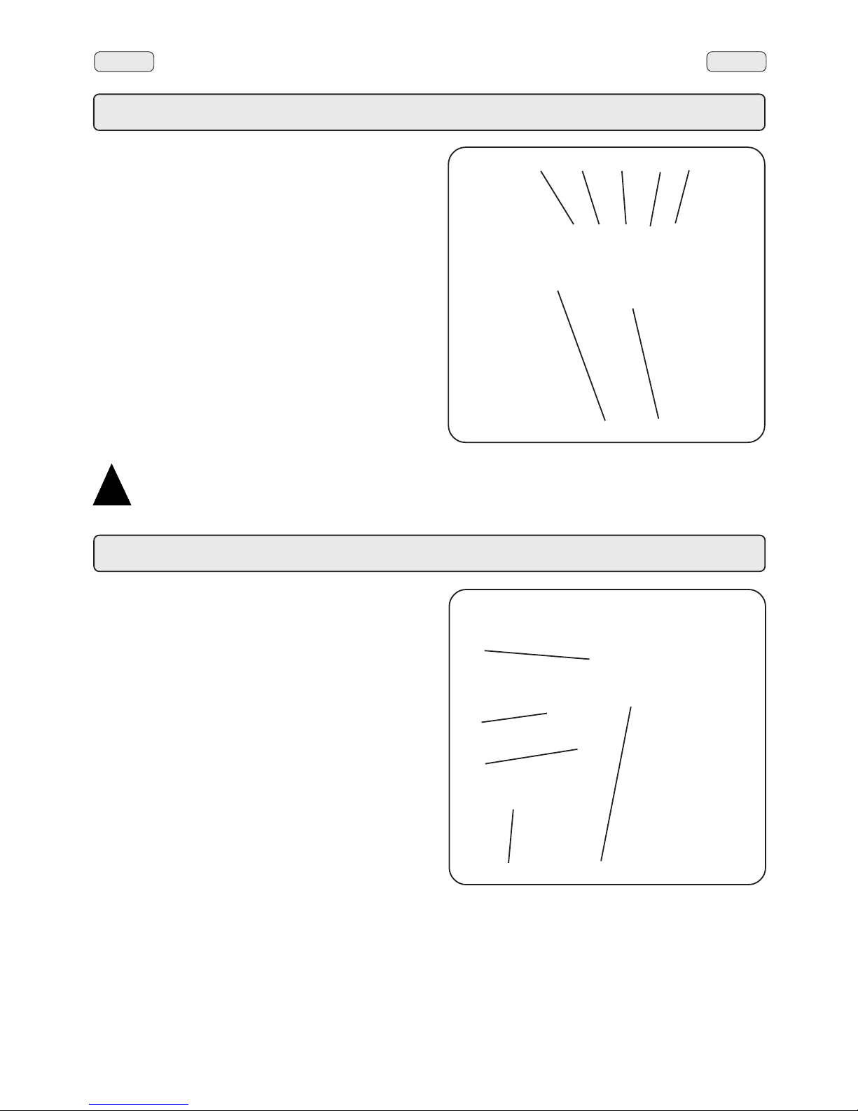
EnglishEnglish
53
6.3 Drinks distribution - cappuccino (only if the cappuccino function is active)
Use only the filter carrier (21) with a one-way spout and
the distribution group to the left.
After having removed the filter carrier (21) from the group and
emptied it of the previous grounds, fill with a new dose of
ground coffee and press.
Insert the filter carrier into the group, locking it well in place.
Place the cappuccino maker (18) close to the filter carrier
spout (21).
Position the cappuccino cup, or a suitable container in such
a way so that the coffee and milk can flow into the cup without
having to move it between the two flows.
Press one of the cappuccino distribution keys (26, 27, 28 or
29). The led above the selected key lights up, distribution
commences and then stops automatically.
It is possible to stop the distribution at any time by pressing
the continuous/STOP key (30).
As described in Chapter “Programming the cappuccino
distribution keys”, it is possible to select whether to distribute
first the milk and then the coffee or vice versa.
Paragraph, “User Instructions for the Cappuccino Maker”
describes how to adjust the temperature of the milk and the
density of the milk froth.
“When the machine is not used for a long period of
time, comply with the hygiene procedures regarding
preservation of milk”.
!!
!!
!
21
2928
3027
26
18
6.4 Cappuccino maker instruction
18
18d
18c
18b
18a
Insert the tube (18d) into the milk.
Place a container under the cappuccino maker (18).
Remove the knob (18b) to facilitate the circulation of air.
Completely rotate the air adjustment screw (18a) clockwise,
then turn it back by half a turn.
Completely rotate the temperature adjustment screw (18c)
clockwise, then turn it back by half a turn.
At this point, press the required key to obtain milk or
cappuccino.
Adjustment of the cappuccino froth
Too much froth:
Finely rotate the air adjustment screw (18a) clockwise.
Too little froth:
Finely rotate the air adjustment screw (18a) anticlockwise.
Cappuccino temperature
If the cappuccino is too hot:
Finely rotate the temperature adjustment screw (18c)
anticlockwise.
If the cappuccino is not hot enough:
Finely rotate the temperature adjustment screw (18c
clockwise.
Distribution of hot unwhipped milk
Press and completely push in the knob (18b), then press the
desired milk or cappuccino distribution key.
Page 34
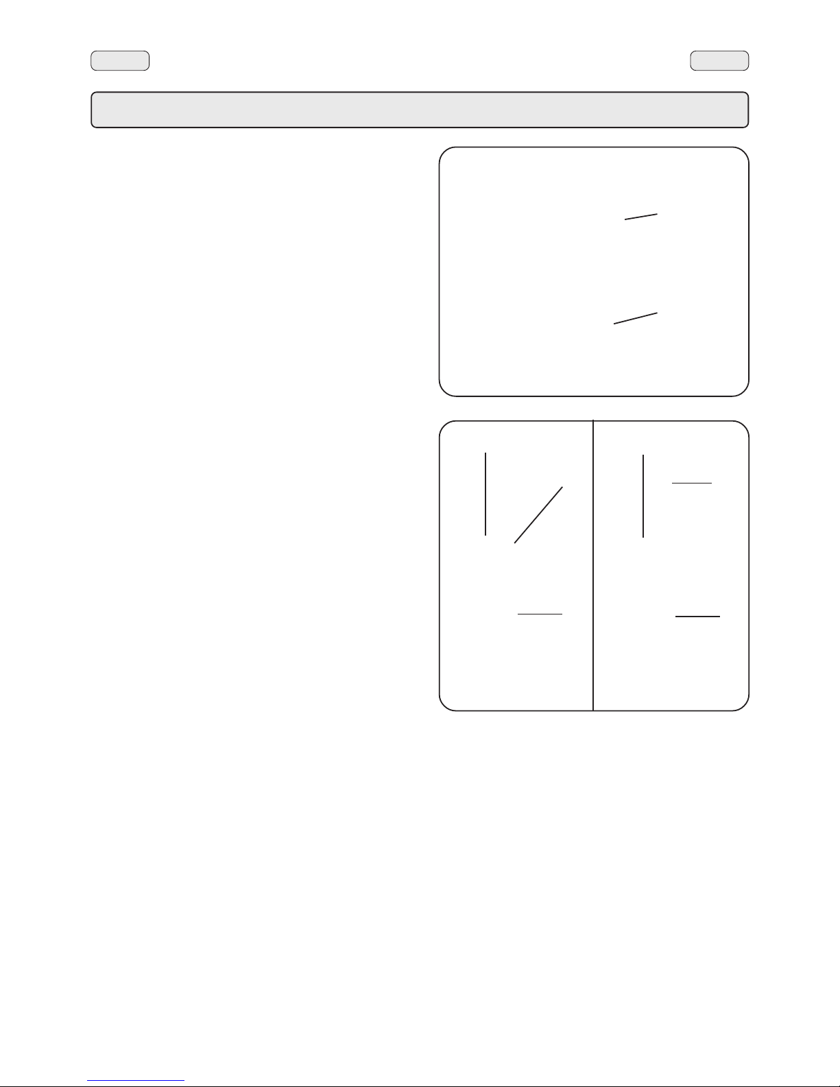
EnglishEnglish
54
6.5 Drinks distribution - steam
Completely immerse the right (9) or left (20) steam nozzle
into the container with the liquid to be heated and push the
steam control lever (11 or 17) upwards.
Wait until the liquid has reached the desired temperature,
then lower the steam command lever to stop the issue of
steam.
Note: At the conclusion of each steam dispensing phase,
clean the inside of the steam nozzle as follows:
Turn the nozzle towards the cup tray and carefully
activate steam dispensing at least once.
Dispensing with the Autosteam (Turbosteam) selector (12)
(when provided)
Machines equipped with the AUTOSTEAM (STOP STEAM)
dispensing system have the "stop steam dispensing when
set temperature is reached" function, and can rapidly heat
and froth milk.
Steam is dispensed when the key (12) is pressed, and the
lever (11) is pressed for the type of milk.
In particular:
- lever down: foamed milk
- lever up: heated milk.
After selecting the type of milk you desire (heated or frothed),
insert the steam nozzle (9) into a suitable container, making
sure the bulb is completely immersed in the milk.
After pressing the key (12), the temperature detected by the
probe appears on the display.
When the temperature is reached, steam dispensing can be
stopped either automatically or manually, as described in
paragraph "2.5 User dosage - automatic steam dispensing
key programming"
9
11
9
12
11
9
12
11
Frothed milk
Hot milk
Page 35
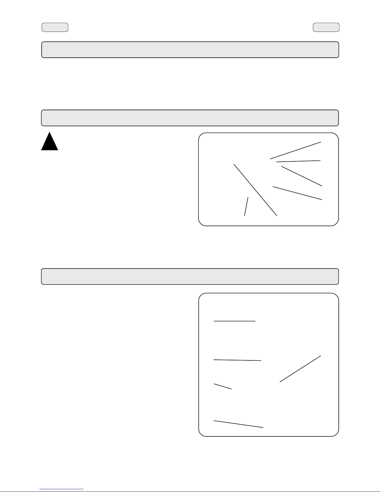
EnglishEnglish
55
The machine is fitted with a series of automatic level control
devices to keep the water in the boiler at a pre-set level.
The indicator light (4) comes on when water enters the boiler.
Filling the boiler with water using the manual service tap
This function should be used only if the electronic level control
devices are not working correctly.
Push the manual boiler water fill lever (22), taking care not to
exceed the MAX level on the optic indicator (19).
7. Water level control of boiler
9. Cleaning
Cleaning the cappuccino maker
This operation must be made at the end of each working day.
1. Fill a container with 0,5 litre of cold water and one dose of
liquid detergent (see product instructions).
2. Remove the suction (18d) tube from the milk container and
immerse it in the solution.
3. Press button (16) and repeat the operation until all the
detergent has been used up.
4. Disassemble the cappuccino maker (18):
Unscrew the knob (18b) and remove the cappuccino
maker (18).
Remove the cover.
Unscrew the ring nut of the knob (18b) and remove it.
Unscrew and remove the adjustment screw (18a).
Prepare another dose of detergent and clean each piece.
Remove any residue with a sponge.
Reassemble the cappuccino maker.
5. Rinse, pumping out at least one litre of cold water.
18
18d
18b
18a
16
!!
!!
!
Before operating the machine, perform a rinse of
theinternal circuits and change the water in the
boiler.”
8.1 Changing the water in the internal groups circuits
Remove the filter carriers (21, 25) of the distributor groups.
Via the continuous distribution key (30), empty the water from
each group for approximately one minute. Repeat this
operation twice.
8.2 Changing the water in the boiler
Ensure that the indication on the display corresponds to the
working pressure value.
Keep the hot water distributor key (13a - 13c) pressed down
for approximately 5 seconds.
The following message will be displayed: “water change”,
followed by an audio signal. The water from the boiler will
drain from the hot water nozzle (10).
All the other keys will be deactivated.
8. Rinsing
!!
!!
!
10
13c
13b
13a
30
21/25
When only steam is issued from the nozzle (10), press the
hot water stop key (13b).
The machine will return to its normal functions and the boiler
will be refilled with water.
Page 36
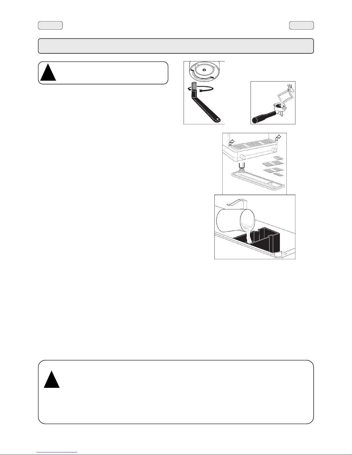
EnglishEnglish
56
9. Cleaning and maintenance
Cleaning dispensing unit
This operation must be made on all the groups at the end
of each working day
1) Using a brush, clean the cover gasket.
2) Insert the rubber disk into the filter-holder with its filter.
3) Pour in a packet or dosing cupful of detergent powder
4) Insert the filter carrier into the group and press the selection
button. After a few seconds, press the STOP button.
Repeat this operation a few times.
5) Remove the filter-holder and clean the shower with a
sponge.
6) Flush each dispenser unit with water for about 30
seconds.
First left-hand dispenser unit with cappuccino-selection
panel:
1) Remove the milk-aspiration tube from the milk container
and rest it against the grille of the cup-shelf basin.
2) Press one of the selection buttons. Wait a few seconds
and press the STOP button. Repeat this operation a few
times. Be careful, steam will come out of the cappuccinomaker’s dispensing spout.
Filter-holders
1) Put a liter of cold water in a suitable container and add
detergent.
2) Soak the filter-holders in this solution for about 2 hours.
3) Remove the filters from the filter-holders and wash the
parts in the same detergent solution, using a small
sponge.
4) Flush thoroughly with cold water.
5) Reinstall the filters in the filter-holders, making sure that
filter-retainer spring seats properly.
Steam and hot water dispensing pipes
Using a clean sponge, wash with hot water removing any
organic residue present. Rinse carefully.
To clean the inside of the steam nozzle, follow these steps:
Turn the nozzle towards the cup tray and carefully activate
steam dispensing at least once.
For correct application of the HACCP system,
please follow the instructions in this paragraph.
!!
!!
!
ATTENTION
When the machine has not been used for more
than 8 hours, and in any case once a day, the
internal components must be washed before
use, in accordance to the following
instructions:
Supply Groups
Insert the filter carriers into the groups (without coffee)
and dispense from each group for one minute.
Hot water
Dispense hot water repeatedly (using the relative
command) until at least 6 liters of water have been
dispensed from the 2-group machine, 9 liters of water
from the 3-group machine and 12 liters from the 4-group
machine.
Steam
Allow the steam to flow for approximately one minute,
using the appropriate commands.
!!
!!
!
Grille and Drip Basin
Remove the grille from the basin, extract the grille sections
and complete the cleaning operation under running water.
Discharge Basin
At the end of the working day, pour about a liter of hot water
into it to remove any discharge residues.
Bodywork
Use a soft cloth and cleaning products WITHOUT ammonia
or abrasives, removing any organic residue present in the
work area.
N.B. Do not spray liquids into the panel slots.
2
1
Page 37
EnglishEnglish
57
10. Caution
MAINTENANCE AND REPAIR
If the machine does not function correctly , switch it off, turn off
the main switch and call the service agent.
Only qualified and authorised servicing personnel should
be called.
Use only original spare parts.
Maintenance activities performed by unqualified personnel
may jeopardise the safety of the machine.
If the electric cable is damaged, switch off the machine and
apply to the servicing department for a replacement.
Regeneration of the Water Softener
The machine must be installed with an ionic resin water
softener.
The water softener may be of different types, with different
resin capacities and different periods of validity.
The resins are regenerated by adding coarse kitchen salt or
salt pastilles to the water softener.
If the regeneration of the resins is not made at the due dates,
calcareous deposits will form which progressively decrease
the machine’s efficiency until its functions are completely
blocked.
The regeneration due dates and method thereof may be
found in the instructions provided with the equipment.
If regeneration is performed at the due dates, the machine is
maintained in ideal working conditions.
GENERAL
Use of gas operated appliances in premises smaller than
12 m2 is not permitted.
If a gas heated installation is used, change the flexible
tube at the due expiry date.
The manufacturer disclaims all liability for damages to
items or persons due to improper use or due to the coffee
machine being used for reasons other than its intended
use.
Never work the coffee machine with wet hands or naked
feet.
Cup-warming plate
Place only coffee cups, cups and glasses to be used in
conjunction with the coffee machine on the cup-warming
plate.
Ensure that the coffee cups are completely drained before
placing them on the cup-warming plate.
No other objects shall be placed on the cup-warming plate.
Danger of Burns
Do not place the hands or other parts of the body close to the
coffee distribution points, or near to the steam and hot water
nozzles.
Ensure that the machine is not handled by children or
persons who have not been instructed in its correct use.
Danger of burns
The areas marked with this sign become hot.
Great care should be taken when in the vicinity
of these areas.
WARNING: Hot surface
ACHTUNG: Heisse Oberfläche
ATTENTION: Surface chaude
ATTENZIONE: Superficie calda
!!
!!
!
MACHINE CLOSE-DOWN
When the machine remains unattended for a
long period of time (at night, during the weekly
closing day or during holidays) the following
operations shall be performed:
- Remove the plug or switch off the main
switch.
- Close the water tap.
- Close the gas tap.
Non-compliance with these safety measures
exonerates the manufacturer from all liability
for malfunctions or damage to persons or
items.
!!
!!
!
The following measures are indispensable for
ensuring operational and functional safety:
- Comply with all the manufacturer’s
instructions.
- Ensure that specialized technicians
periodically verify that the protection
devices are intact and that all the safety
devices function correctly (the first
inspection should be made within 3 years
and subsequently once yearly).
!!
!!
!
Page 38

EnglishEnglish
58
11. Malfunctions
Direct intervention by the customer
In order to avoid unnecessary costs, ensure that the problem occurring in the machine is not included in the following table
before calling the servicing department.
DEFECT
The coffee machine does not function
and the indicator light (2) is off.
The coffee machine does not work but
the indicator light (2) is on.
The coffee machine does not heat up.
Leak from edge of filter-holder (21,
25).
Coffee flow time too short.
Water leaks from under the machine.
The coffee is warm and weak (after
normal time of brew and flow).
The reading on the pressure gauge
(8) of the pump pressure is greater
than 9 bars.
REMEDY
Check that the electricity is on.
Check the position of the main switch
(12).
Press the PROGR (32) key for a few
seconds to force switch-on.
Reprogram the clock
Press the switch knob (1a).
Clean with the supplied brush.
Grind the coffee more finely.
Change the coffee
Clean the tank.
Press the coffee distribution button 2/
3 times to try and eliminate the air
bubble.
Call the authorized servicing
department.
CAUSE
No electricity.
Wrong programming of the switch-on
times.
Wrong position of the switch (1a).
The undercup gasket is dirty with
coffee residue.
Coffee grinds too coarse.
Coffee too old.
Drainage tank clogged.
Air bubble in thermosyphonic
circulation system.
The pump’s by-pass valve is blocked.
Page 39
EnglishEnglish
59
INDEX
Page
PROGRAMMING - USER MODE
1. Data flow chart - Customer programming 60
2. Clock adjustment 61
3. How to access the programming mode 61
3.1 Programming the coffee distribution keys 62
3.2 Programming the cappuccino distribution 62
3.3 Programming the milk distribution key 64
3.4 Programming the hot water distribution keys 65
3.5 Programming the automatic steam key - AUTOSTEAM 66
4. Service time menu 67
5. Counter display and zeroing 68
6. Language selection 68
Page 40
EnglishEnglish
60
1. Data flow chart - Customer programming
Only if "Prog. cliente" is YES
To ACCESS menu press PROG
To EXIT menu press
444444
444444
444
$
#
CUSTOMER PROG.
KEY MENU
+
u
u
selection XXX
Milk dose 03.6s
+
u
u
selection XXX
coffee start 10
+
u
u
selection XXX
Water dose 090
+
u
u
CUSTOMER PROG.
SERVICE TIME
+
u
u
SERVICE TIME
DAY AND TIME
+
u
u
DATE AND TIME
DAY friday
+
u
u
DATE AND TIME
Hour 09
+
u
u
DATE AND TIME
Minutes 32
+
u
u
SERVICE TIME
TIME ON - DURATION
+
u
u
START PERIOD
08:25 MON 09:15
+
u
u
START PERIOD
08:05 TUE 09:10
+
u
u
...............
...............
START PERIOD
08:25 MON 09 :15
+
u
u
CUSTOMER PROG.
COUNTERS
+
u
u
COUNTERS
N° coffee GR1 25
+
u
u
COUNTERS
N° coffee GR1 25
+
u
u
N° coffee GR....
N° milk
N° water
N° steam
N° steam TS
N° steam + air TS
N° tot coffee
COUNTERS
N° coffee GR1 00
+
u
u
PROG
PROG
PROG
PROG
PROG
PROG
PROG
-
-
-
-
-
-
-
-
-
+
-
444
selection XXX
Milk dose 03.6s
+
u
u
Use the keys
to modify the message or number:
Press the key to confirm/
exit the menu:
Modifying data
Press the key;
When modifying data, the cursor
"
" changes to " ":
PROG
+
-
444
selection XXX
Milk dose 03.6s
+
u
u
selection XXX
Milk dose 02.4s
+
u
u
selection XXX
Milk dose 02.4s
+
u
u
Friday 09:20
Boiler P. 1.1bar
CUSTOMER PROG.
LANGUAGE
+
u
u
LANGUAGE
ITALIANO
+
u
u
ENGLISH
FRANCAIS
DEUTSCH
NEDERLANDS
ESPANOL
PORTUGUES
JAPONESE
PROG
-
-
Page 41
EnglishEnglish
61
Use the “+” (34) and “-” (35) keys to adjust the clock.
The time increases (or decreases) one minute each time
the key is pressed.
The time changing speed increases if one of the keys (34 or
35) is kept depressed.
2. Clock adjustment
3. How to access the programming mode
N.B. ONLY if the item “Customer Progr.” is set on “YES".
To access programming press the PROG (32) key; the following
message will appear on the display:
Press one of the dispensing keys on the selection panel; the
relative led will remain on.
Use the “+” (34) and “-“ (35) keys to position the cursor on the
desired line, then press the PROG (32) key.
Always use the "+" (34) and "-" (35) keys to change the setting;
confirm the changes made by pressing the
444444
444444
444
key.
Note: when modifying data, the cursor changes to "
ÆÆ
ÆÆ
Æ".
If the "Customer Progr." is set to "NO", the following message
will appear on the display:
CUSTOMER PROG.
NOT ENABLED!
ÀCUSTOMER PROG.
KEY MENU
+
u
u
fryday 09:20
Boiler P. 1.1bar
Page 42
EnglishEnglish
62
3.1 Programming the coffee distribution keys
Press one of the coffee dispensing keys on the selection
panel (the relative led will remain on, not flashing). The
following message will appear on the display:
Each dispensing unit is controlled by a panel that permits
programing the amount of desired dispensing for each
button.
The following coffee selection parameters can be modified:
- water dose (volumetric dosage pulses, from 0 to 999, with
increments of 1).
Programming measures using the “SELF-LEARNING”
function
To perform the coffee dose programming, follow the
procedure herebelow:
1) Fill the filter carrier (21) with the correct dose of ground
coffee) and insert into the group ensuring it is correctly
locked in place (do not use previously used coffee
grounds).
2) Place the cup by the filter carrier spout (21).
3) Press the PROG (32) key; the following message will
appear on the display:
when modifying data, the cursor changes to "
ÆÆ
ÆÆ
Æ".
4) Keep the distributor key pressed, as evidenced by the
flashing led (the coffee dose counter starts from zero and
increases in value).
selection XXX
Water dose 090
+
u
u
selection XXX
Water dose 090
+
u
u
ÆÆ
ÆÆ
Æ
selection XXX
Water dose 090
+
u
u
21
5) When the quantity of the coffee in the cup has reached the
desired level, release the key (the counter will indicate the
number of pulses that correspond to the set dose).
It is also possible to vary the coffee doses or set the dose
using the “+” (34) and “-” keys (35).
When the key
444444
444444
444 (33) is pressed, the following message
is again displayed:
3.2 Programming the cappuccino distribution keys
Press one of the cappuccino dispensing keys. The related
LED remains on and does not blink. The display appears as
follows:
Cappuccino selection parameters that can be changed are:
- Milk dose (milk dispensing time: 0 ÷ 60 seconds, with
increments of 0.1);
- Milk start/coffee start ** (milk dispensing delayed after
coffee dispensing, and vice versa)
- Water dose (volumetric dosage pulses, from 0 to 999, with
increments of 1).
selection XXX
Milk dose 03.6s
+
u
u
26
27
18
21
Page 43
EnglishEnglish
63
Programming measures using the “SELF-LEARNING”
function: milk dose
To memorize the programming of the milk dose, follow the
procedure herebelow:
1) Place the cup by the cappuccino maker (18).
2) Press the PROG (32) key; the following message will
appear on the display:
when modifying data, the cursor changes to "
ÆÆ
ÆÆ
Æ".
3) Keep the distributor key pressed, as evidenced by the
flashing led (the coffee dose counter starts from zero and
increases in value).
selection XXX
Milk dose 03.6s
+
u
u
ÆÆ
ÆÆ
Æ
selection XXX
Milk dose 03.6s
+
u
u
4) When the quantity of milk in the cup has reached the
desired level, release the key (the counter will indicate the
rime that correspond to the set dose).
It is also possible to vary the milk dose or set the dose using
the “+” (34) and “-” keys (35).
N.B.: If the coffee dose is set to “00.0”, the key may only be
used for coffee distribution.
When the key
444444
444444
444 (33) is pressed, the following message
is again displayed:
Programming measures using the “SELF-LEARNING”
function: coffee dose
To perform the coffee dose programming, follow the
procedure herebelow:
1) Fill the filter carrier (21) with the correct dose of ground
coffee) and insert into the group ensuring it is correctly
locked in place (do not use previously used coffee
grounds).
2) Place the cup by the filter carrier spout (21).
3) Press the PROG (32) key; the following message will
appear on the display:
when modifying data, the cursor changes to "
ÆÆ
ÆÆ
Æ".
4) Keep the distributor key pressed, as evidenced by the
flashing led (the coffee dose counter starts from zero and
increases in value).
selection XXX
Water dose 090
+
u
u
ÆÆ
ÆÆ
Æ
selection XXX
Water dose 090
+
u
u
5) When the quantity of the coffee in the cup has reached the
desired level, release the key (the counter will indicate the
number of pulses that correspond to the set dose).
It is also possible to vary the coffee doses or set the dose
using the “+” (34) and “-” keys (35).
When the key
444444
444444
444 (33) is pressed, the following message
is again displayed:
(**) Start milk/Start coffee function
By setting:
"Start milk 00" - milk dispensing takes place when the
selection key is pressed. After a few seconds, coffee is
dispensed;
"Start milk 99" or at a high setting that exceeds the coffee
dispensing time - milk dispensing starts after coffee is
dispensed.
"Start milk 05" - coffee dispensing starts, and 5 seconds after
the selection key is pressed, milk is dispensed.
Note: If the time setting exceeds the coffee dispensing time,
milk dispensing begins immediately after coffee is dispensed.
"Start coffee 00" - Coffee dispensing starts after milk is
dispensed.
"Start coffee 99" or any setting other than 0 - coffee dispensing
will start 99 seconds (or after the set time) after milk is
dispensed.
The cappuccino beverage can be made as follows:
- First dispensing coffee and then milk.
- First dispensing milk and then coffee.
You can use the"+" (34) and "-" (35) keys to change the "Start
milk" setting (milk dispensing start delayed after coffee
dispensing and vice versa) from "00" to "99" with "1" second
increments.
If over "99" is set, the "Start milk" setting will become the "Start
coffee" setting (coffee dispensing start delayed after the milk
dispensing), then the setting returns to "Start milk" in a cycle.
The default settings for
cappuccino selections
are: Start milk 00.
Start Milk
Start Coffee
00 99
0099
Page 44
EnglishEnglish
64
3.3 Programming the milk distribution key
N.B.: Also valid if the CAPPUCCINO function is not activated.
When the milk distribution key (16) is pressed (shown by the
flashing led), the following message will be displayed:
Milk selection parameters that can be changed are:
- Milk dose (milk dispensing time: 0 ÷ 60 seconds, with
increments of 0.1).
Programming measures using the “SELF-LEARNING”
function: milk dose
To memorize the programming of the milk dose, follow the
procedure herebelow:
1) Place the cup by the cappuccino maker (18).
2) Press the PROG (32) key; the following message will
appear on the display:
when modifying data, the cursor changes to "
ÆÆ
ÆÆ
Æ".
3) Keep the distributor key pressed, as evidenced by the
flashing led (the coffee dose counter starts from zero and
increases in value).
4) When the quantity of milk in the cup has reached the
desired level, release the key (the counter will indicate the
rime that correspond to the set dose).
It is also possible to vary the milk dose or set the dose using
the “+” (34) and “-” keys (35).
When the key
444444
444444
444 (33) is pressed, the following message
is again displayed:
selection XXX
Milk dose 03.6s
+
u
u
16
18
selection XXX
Milk dose 03.6s
+
u
u
ÆÆ
ÆÆ
Æ
selection XXX
Milk dose 03.6s
+
u
u
Page 45
EnglishEnglish
65
3.4 Programming the hot water distribution keys
Press one of the hot water distribution keys (13a - 13c). The
related LED remains on and does not blink. The display
appears as follows:
The following hot water selection parameters can be
modified:
- water dispensing time (from 0 to 60, with increments of
0.1 seconds).
Programming measures using the “SELF-LEARNING”
function
To memorize the programming of the hot water dose, follow
the procedure herebelow:
1) Place a container by the hot water distribution nozzle (10).
2) Press the PROG (32) key; the following message will
appear on the display:
3) Keep the distributor key pressed, as evidenced by the
flashing led (the hot water dose counter starts from zero
and increases in value).
selection XXX
dispens. time 05.0s
+
u
u
selection XXX
dispens. time 05.0s
+
u
u
10
13c
13b
13a
selection XXX
dispens. time 05.0s
+
u
u
ÆÆ
ÆÆ
Æ
4) When the quantity of water in the container has reached
the desired level, release the key (the counter will indicate
the time that corresponds to the set dose).
It is possible to vary the set dose via the “+” (34) and “-” (35)
keys (the time of the water distribution can also be increased
or decreased).
When the key
444444
444444
444 (33) is pressed, the following message
is again displayed:
Page 46
EnglishEnglish
66
3.5 Programming the automatic steam key - AUTOSTEAM (Turbosteam)
When the automatic steam dispensing key (12) is pressed
(indicated by the relative led), the following message is
displayed:
Press the PROG (32) key; the following message will
appear on the display:
You may now program the automatic steam function, by
setting a “xxx°C” temperature value for either hot or whipped
milk.
Setting options:
- "0" setting:
• manual steam stop
Note: The user controls when steam dispensing is
stopped. When the desired temperature is reached, the user
will push on key (12).
- Any number between "40°C ÷ 85°C" (104°F ÷ 185°F)
• automatic steam stop
- "OFF" setting:
• steam stop disabled
Use the “+” (34) and “-” (35) keys also to modify the message
or number.
When the key
444444
444444
444 (33) is pressed, the following message
is again displayed:
When the key
444444
444444
444 (33) is pressed another time, the
following message is displayed:
selection 021
T stop steam 070°C
+
u
u
selection 021
T stop steam 070°C
+
u
u
ÆÆ
ÆÆ
Æ
selection 021
T stop steam 070°C
+
u
u
12
ÀCUSTOMER PROG.
KEY MENU
+
u
u
Page 47
EnglishEnglish
67
4. Service time menu
fryday 09:20
Boiler P. 1.1bar
To access "service time" menu, press the PROG key (32)
and then the key "-" (35); the message shown below will
appear on the display:
Pressing the PROG key (32), the following message will
appear on the display:
Press the PROG (32) key.
Use the “+” (34) and “-“ (35) keys to move the cursor to the
entry to be modified, then press the PROG (32) key. The
cursor will turn into an arrow and it becomes possible to
change the number for the selected entry by using the “+”
(34) and “-“ (35) keys.
Once the operation is completed, press the
444444
444444
444
(33) key to
confirm the data.
Repeat the operation described above to modify other
parameters.
Pressing the "-" key (35) the following message will appear
on the display:
Pressing the PROG key (32), the following message will
appear on the display:
When the PROG key (32) is pressed another time, the activation
hour (e.g. 07) flashes.
Press the “+” (34) and “-” (35) keys until the correct activate
hour for Monday is displayed.
N.B. If the “+” (34) and “-” (35) keys are kept depressed, the
hours number changes at a greater speed.
When the PROG key (32) is pressed, the minutes of the
switch-on time will flash on the display (e.g. 30). Using the "+"
(34) and "-" keys (35) this figure can be changed to show the
corresponding minutes of the desired switch-on time.
ÀCUSTOMER PROG.
SERVICE TIME
+
u
u
ÀSERVICE TIME
DA Y AND TIME
+
u
u
ÀSERVICE TIME
ST ART AND PERIOD
+
u
u
START PERIOD
07:30 MON 16:30
+
u
u
When the PROG key (32), is pressed, the hour of the operation
time will flash on the display (e.g. 16). Using the "+" (34) and
"-" keys (35) this figure can be changed to show the
corresponding hour of duration for Monday.
When the PROG key (32) tis pressed, the minutes of the
operation time will flash on the display (e.g. 30). Using the "+"
(34) and "-" keys (35) this figure can be changed to show the
desired number of minutes.
Examples
1) When the set day (e.g. Monday) corresponds to the closing
day, set the activation time to “00:00” and the duration to
“00:00”.
2) If the machine needs to remain on at all times, set the
time of activation to “00:00” and the duration to “24:00”.
3) If the machine needs to be switched on at 07:30 and switch
off at midnight, set the activation time to “07:30” and the
duration to “16:30”.
How to perform other operations
When the PROG key (32) is pressed, the activation time will
once again be displayed (if this needs to be changed, follow
the above procedures).
Pressing the
444444
444444
444
(33) key, the following message will appear
on the display:
When the "-" (35) key is pressed, the message “ activate
duration “ for the next day is displayed:
START PERIOD
07:30 MON 16:30
+
u
u
START PERIOD
08:20 TUE 18:00
+
u
u
Page 48
EnglishEnglish
68
5. Counter display and zeroing
To access "Counters" menu, press the PROG key (32) and
then the key "-" (35) until the message shown below will
appear on the display:
Pressing the PROG key (32), the following message will
appear on the display:
Parameters calculated are:
- N. coffee (number of coffee beverages)
- N. milk (number of milk beverages)
- N. water (number of times water is dispensed)
ÀCUSTOMER PROG.
COUNTERS
+
u
u
ÀCOUNTERS
N° coffee GR1 25
+
u
u
fryday 09:20
Boiler P. 1.1bar
6. Language selection
fryday 09:20
Boiler P. 1.1bar
To access "Language" menu, press the PROG key (32) and
then the key "-" (35) until the message shown below will
appear on the display:
Press the PROG (32) key; position the cursor on the desired
language by pressing the "+" (34) and "-" (35) keys and then
pressing the PROG (32) key. The machine will restart with the
messages provided in the selected language.
The display (14) provides a choice of the following languages.:
Italian, English, French, German, Dutch, Spanish, Portuguese
and Japanese.
ÀCUSTOMER PROG.
LANGUAGE
+
u
u
- N. steam (number of times steam is dispensed using the
steam button)
- N. steam TS (number of times steam is dispensed using
the autosteam function)
- N. steam + air TS (number of times steam and air are
dispensed using the autosteam function)
- N. tot coffee (total number of coffee beverages).
Counters can be zeroed by aligning the cursor on the selected
entry, pressing the PROG (32) key, and then pressing the ‘+”
(34) or “-“ (35) key.
Press the
444444
444444
444
(33) key to confirm zeroing.
The "N. coffee" entry appears for as many times as there are
machine groups.
Note: Parameters that cannot be zeroed are:
- N. tot coffee
Press the
444444
444444
444
(33) key to return to the main menu.
Page 49
161
EnglishEnglish
INDEX
Page
PROGRAMMING - ENGINEER MODE
1. Data flow chart - Technician programming 162
2. Programming 164
3. Technician programming - Coffee selection 164
4. Technician programming - Cappuccino Milk selection 164
5. Technician programming - Hot water selection 165
6. Technician programming “SELF-LEARNING” function 16 5
7. Technician programming - Configuration menu 165
8. Technician programming - Configuration menu Data menu 167
9. Technician programming - Configuration menu Components test 16 9
10. Technician programming - Configuration menu Autosteam 170
1 1. Check-control messages 171
Page 50
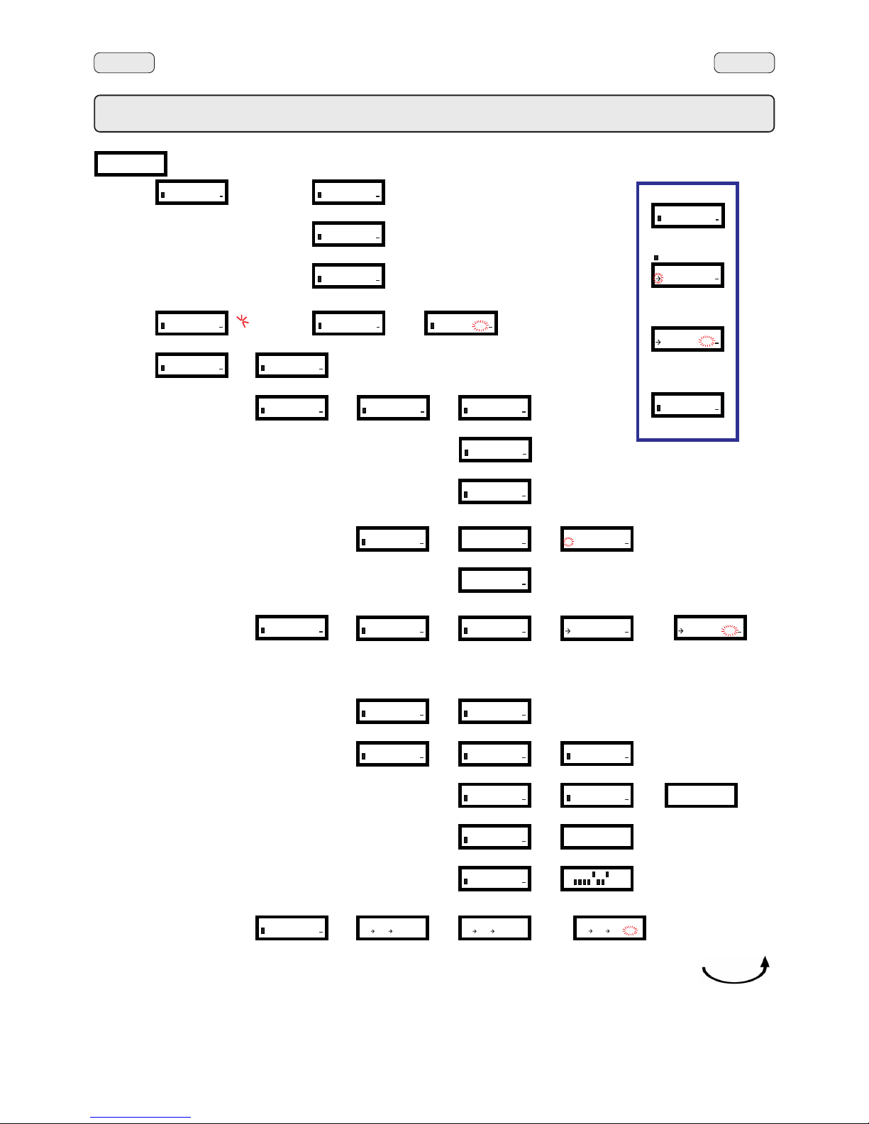
162
EnglishEnglish
1. Data flow chart - Technician programming
TECHNICAL PROG.
KEY MENU
+
u
u
selection XXX
Milk dose 03.6s
+
u
u
selection XXX
coffee start 10
+
u
u
selection XXX
Water dose 090
+
u
u
TECHNICAL PROG.
SELF-LEARNING
+
u
u
selection XXX
Water dose 082
+
u
u
TECHNICAL PROG.
CONFIGURATION
+
u
u
CONFIGURATION
Boiler P. 1.0 bar
+
u
u
CONFIGURATION
SERVICE TIME
+
u
u
SERVICE TIME
DAY AND TIME
+
u
u
DATE AND TIME
DAY friday
+
u
u
DATE AND TIME
Hour 09
+
u
u
DATE AND TIME
Minutes 32
+
u
u
SERVICE TIME
TIME ON - DURATION
+
u
u
START PERIOD
08:25 MON 09:15
+
u
u
start period
08:05 TUE 09:10
+
u
u
...............
...............
CONFIGURATION
DATA MENU
+
u
u
CONFIGURATION
COMPONENTS TEST
+
u
u
P 1.1bar Liv. OK
± PRG MP :RES
P 1.1bar Liv. OK
± PRG MP :OFF
G1...
Eac
Evc
Ets
MC
Eds
Em
selection XXX
Water dose 090
+
u
u
START PERIOD
08:25 MON 09:15
+
u
u
P 1.1bar Liv. OK
± PRG MP :ON
INFO
SETUP
+
u
u
INFO
DIP SETTINGS
+
u
u
– –
Capp. - coffee
Steam
TS
Electric
Menù 1
1
8 ON
OFF
Friday 09:20
Boiler P. 1.1bar
COUNTERS
N° coffee GR1 25
+
u
u
N° coffee GR....
N° milk
N° water
N° steam
N° steam TS
N° steam + air TS
N° tot coffee
COUNTERS
N° coffee GR1 00
+
u
u
PROG
PROG
PROG
PROG
PROG
PROG
PROG
PROG
PROG
PROG
PROG
PROG
PROG
PROG
PROG
PROG
PROG
PROG
-
-
-
-
-
-
-
-
-
-
-
-
-
-
-
-
-
-
+
-
-
+
-
+
-
+
-
444
444
444
444
444
444
444
selection XXX
Milk dose 03.6s
+
u
u
Use the keys
to modify the message or number:
Press the key to confirm/
exit the menu:
Modifying data
Press the key;
When modifying data, the cursor
"
" changes to " ":
PROG
+
-
444
selection XXX
Milk dose 03.6s
+
u
u
selection XXX
Milk dose 02.4s
+
u
u
selection XXX
Milk dose 02.4s
+
u
u
DATA MENU
COUNTERS
+
u
u
COUNTERS
N° coffee GR1 25
+
u
u
DATA MENU
MALFUNCT. ARCHIVE
+
u
u
MALFUNCT. ARCHIVE
01 XXX 23:44
+
u
u
DATA MENU
INFO
+
u
u
INFO
SERIAL NUMBER
+
u
u
SERIAL NUMBER
1234567
+
u
u
INFO
VERSION
+
u
u
VERSION
DISPLAY 029.T0.A0
+
u
u
DISPLAY 029.T0.A0
REV. 00 20/04/2006
STANDARD DATA
– –
4 GR
Page 51
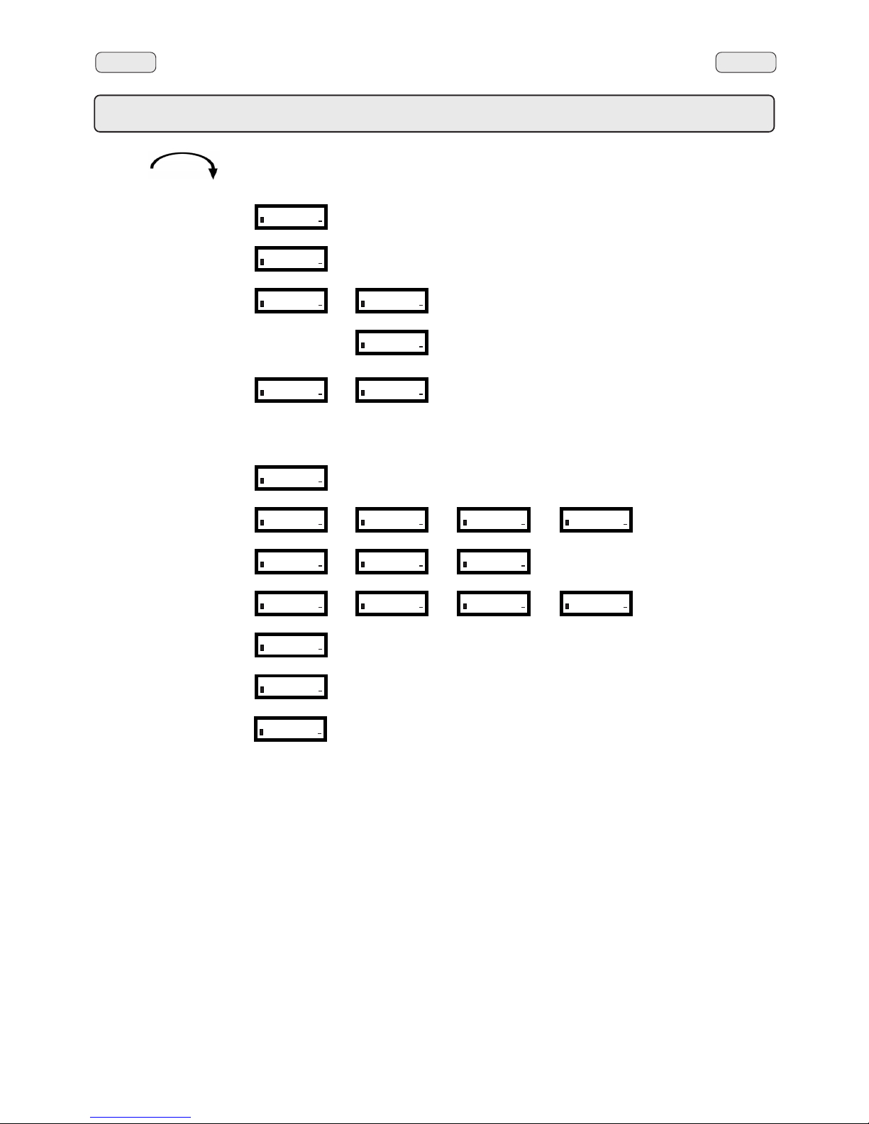
163
EnglishEnglish
1. Data flow chart - Technician programming
CONFIGURATION
Customer prog. YES
+
u
u
CONFIGURATION
Cappuccino func. YES
+
u
u
CONFIGURATION
SOFTNER REGENERATION
+
u
u
SOFTNER REGENERATION
Softner 1 0.0l
+
u
u
SOFTNER REGENERATION
Hardness 08.0F
+
u
u
CONFIGURATION
LANGUAGE
+
u
u
LANGUAGE
ITALIANO
+
u
u
ENGLISH
FRANCAIS
DEUTSCH
NEDERLANDS
ESPANOL
PORTUGUES
JAPONESE
CONFIGURATION
Paym. system OFF
+
u
u
CONFIGURATION
DATA IN/OUT
+
u
u
DATA IN/OUT
key 002
+
u
u
DATA IN/OUT
DATA DIRECTION IN
+
u
u
DATA IN/OUT
TX/RX OK
+
u
u
CONFIGURATION
MEASUREMENT UNITS
+
u
u
MEASUREMENT UNITS
temperature °C
+
u
u
MEASUREMENT UNITS
pressure bar
+
u
u
CONFIGURATION
TURBOSTEAM
+
u
u
TURBOSTEAM
T stop steam 081°C
+
u
u
TURBOSTEAM
regulator NO
+
u
u
TURBOSTEAM
emulsion lev. 003
+
u
u
CONFIGURATION
time control YES
+
u
u
CONFIGURATION
Standard data NO
+
u
u
PROG
PROG
PROG
PROG
PROG
-
-
-
-
-
-
-
-
-
-
-
-
-
-
-
-
-
CONFIGURATION
Archive reset YES
+
u
u
-
Page 52
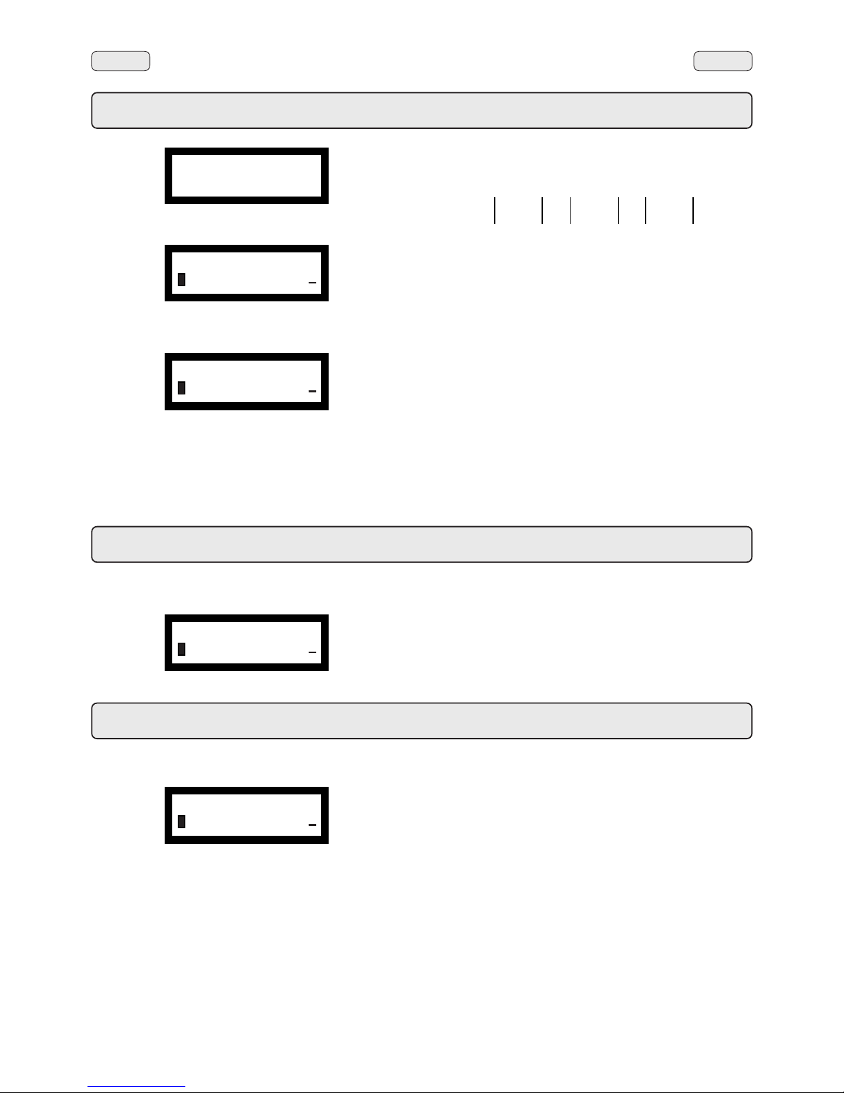
164
EnglishEnglish
Display of available menus: press the PROG (32) key.
Access to menus: Use the “+” (34) and “-“ (35) keys to position the
cursor on the desired line, then press the PROG (32) key (press a
selection key if the ”SELECT KEY” menu appears).
Use the “+” (34) and “-“ (35) keys also to modify the message or
number.
Note: When modifying data, the cursor changes to "
ÆÆ
ÆÆ
Æ".
Exiting the programming menu: press the
444444
444444
444
(33) key.
2. Programming
31 32 33 34 35 36
Press one of the coffee dispensing keys (the relative led will remain
on, not flashing). The following message will appear on the display:
The following coffee selection parameters can be modified:
- water dose (volumetric dosage pulses, from 0 to 999, with
increments of 1).
3. Technician programming - Coffee selection
Press one of the cappuccino – milk dispensing keys. The related LED
remains on and does not blink. The display appears as follows:
Cappuccino-milk selection parameters that can be changed are:
- Milk dose (milk dispensing time: 0 ÷ 60 seconds, with increments
of 0.1);
- Milk start/coffee start ** (milk dispensing delayed after coffee
dispensing, and vice versa)
- Water dose (volumetric dosage pulses: 0 ÷ 999, with increments
of 1).
4. Technician programming - Cappuccino - Milk selection
TECHNICAL PROG.
KEY MENU
+
u
u
Friday 09:20
Boiler P. 1.1bar
selection XXX
Water dose 090
+
u
u
selection XXX
Water dose 090
+
u
u
selection XXX
Milk dose 03.6s
+
u
u
Page 53
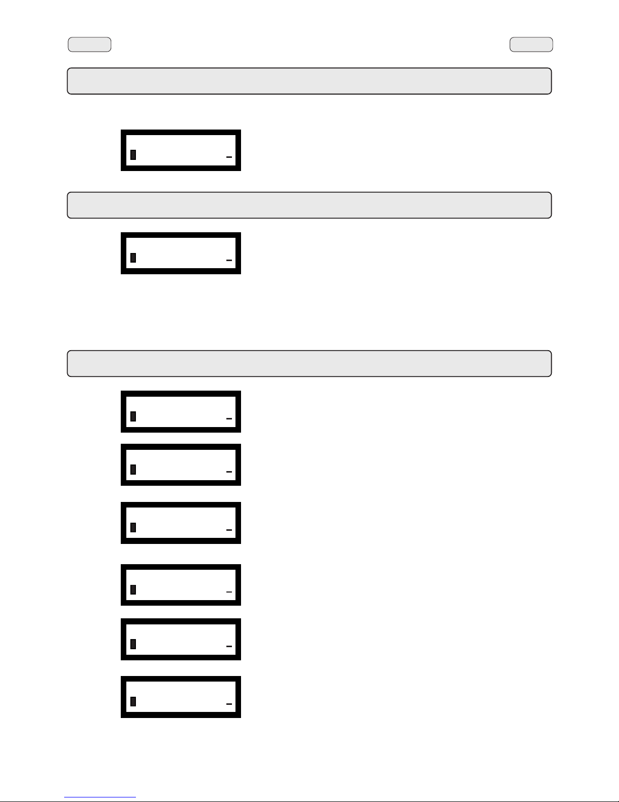
165
EnglishEnglish
Press the hot water dispensing key (13a - 13c). The following
message will appear on the display:
The following hot water selection parameters can be modified:
- water dispensing time (dispensing time in seconds).
5. Technician programming - Hot water selection
selection XXX
dispens. time 05.0s
+
u
u
6. Technician programming - “SELF-LEARNING” function
When one of the dose delivery keys is kept pressed down, (water,
coffee, right steam button) the selection number is displayed and the
programming of the dose is memorized.
In the case of “cappuccino function NO”, if a key on the first group on
the left is programmed, this dose is applied to the equivalent keys of
the other dispensing groups.
In the case of “cappuccino function YES”, by programming the keys
on the group on the left, the dose will be recorded on the equivalent
keys of the other delivery groups, but not on those of the group on
the left (cappuccino group) which will be programmed under “KEY
MENU”.
Boiler pressure – indicates the boiler pressure.
SERVICE TIME - includes 2 sub-menus:
daya and time
start and period: switch on time of the machine and time on.
DATA MENU - includes 3 sub-menus:
counters
malfunction archive
info
See paragraph “Technician programming - Configuration menu - Data menu ”
on the following pages.
Cheks the correct functioning of each component with the display of the name of
the component activated.
See paragraph “echnician programming - Configuration menu - Components
test” on the following pages..
Customer programming – YES/ NO
Cappuccino function – YES/ NO
7. Technician programming - Configuration menu
TECHNICAL PROG.
SELF-LEARNING
+
u
u
CONFIGURATION
Boiler P. 1.0 bar
+
u
u
CONFIGURATION
SERVICE TIME
+
u
u
CONFIGURATION
DATA MENU
+
u
u
CONFIGURATION
COMPONENTS TEST
+
u
u
CONFIGURATION
Customer prog. YES
+
u
u
CONFIGURATION
Cappuccino func. YES
+
u
u
Page 54
166
EnglishEnglish
REGENERATION - includes the parameters for the softner regeneration: liters of
resin (da 0,1l a 25l), hardness (da 0 a 45 °F).
The display provides a choice of the following languages:
Italian, English, French, German, Dutch, Spanish, Portuguese and Japanese.
Payment system – permits configuration of payment system, when connected.
DATA IN/OUT – contains three entries:
Key – indicates the key number from 0 to 60.
Data – IN transfer from smart card to machine. OUT transfer from
machine to smart card.
TX/RX – to start data transfer
MEASURING UNIT – includes 2 sub-menus
Temperature – can be set to °C Celsius centigrade or °F Fahrenheit
degrees.
Pressure – can be set to bar or psi.
TURBOSTEAM (Turbosteam) - includes 2 sub-menus
Stop steam temperature – indicates the automatic stop steam temperature
(Turbosteam). Can be set between a minimum
of 40 and a maximum of 85° C (104 – 185 ° F).
Regolator - flow regolator: YES/ NO.
YES - the machine has the flow regolator on the turbosteam circuit.
NO - the machine does not have the flow regolator; is therefore
possible to set 4 different levels of emulsion.
If “NO” is set, a third line, “emulsion level”, appears: here 4 levels can be chosen,
where 001 is less emulsion and 004 is continuous emulsion.
See paragraph “Technician programming - Configuration menu - Autosteam”
on the following pages.
Time check - view dispensing time on the display: YES/NO
Standard data – loads standard data. YES/NO
Archive reset – zeros the error log (malfunctions archive) stored on the machine:
YES/NO
7. Technician programming - Configuration menu
CONFIGURATION
SOFTNER REGENERATION
+
u
u
CONFIGURATION
LANGUAGE
+
u
u
CONFIGURATION
Paym. system OFF
+
u
u
CONFIGURATION
DA T A IN/OUT
+
u
u
CONFIGURATION
MEASUREMENT UNITS
+
u
u
CONFIGURATION
TURBOSTEAM
+
u
u
CONFIGURATION
time control YES
+
u
u
CONFIGURATION
Standard data NO
+
u
u
CONFIGURATION
Archive reset YES
+
u
u
Page 55
167
EnglishEnglish
8. Technician programming - Configuration menu - Data menu
Press the PROG (32) key; the following message will
appear on the display:
Parameters calculated are:
- N. coffee (number of coffee beverages)
- N. milk (number of milk beverages)
- N. water (number of times water is dispensed)
- N. steam (number of times steam is dispensed using the steam
button)
DATA menu: COUNTERS
- N. steam TS (number of times steam is dispensed using the
autosteam function)
- N. steam + air TS (number of times steam and air are dispensed
using the autosteam function)
- N. tot coffee (total number of coffee beverages).
The "Nr. Coffee" line appears as many times as the number of groups
on the machine.
Counters can be zeroed by aligning the cursor on the selected entry,
pressing the PROG (32) key, and then pressing the ‘+” (34) or “-“ (35)
key.
Note: Parameters that cannot be zeroed are:
- N. tot coffee
DATA menu: MALFUNCTIONS ARCHIVE
If the PROG (32) key is pressed when the cursor is on the “error log”
line, the following appears on the display:
The figures appearing after the “error code” indicate, in hours and
minutes, the time that has passed since the last recorded error.
If the PROG (32) key is pressed again, the details page is accessed.
The following appears on the display:
- day and hour when the error occurred
- machine groups status when the error occurred.
DATA menu: INFO
Press the PROG (32) key; the following message will
appear on the display:
Serial number
CONFIGURATION
DATA MENU
+
u
u
DATA MENU
COUNTERS
+
u
u
DATA MENU
MALFUNCT . ARCHIVE
+
u
u
MALFUNCT. ARCHIVE
01 XXX 23:44
+
u
u
DATA MENU
INFO
+
u
u
INFO
SERIAL NUMBER
+
u
u
SERIAL NUMBER
1234567
+
u
u
Page 56
168
EnglishEnglish
The sub-menu of the Version entry shows the memory display
version:
When the PROG (32) key is pressed displays the data for the revision
and memory date.
Version
INFO
VERSION
+
u
u
VERSION
DISPLAY 029.T0.A0
+
u
u
DISPLAY 029.T0.A0
REV. 00 20/04/2006
The “Setup” entry displays the setup settings introduced during the
Data Standard insertion phase:
Setup
– –
ÆÆ
ÆÆ
Æ Capp. - coffee
Steam
TS
Electric
Menu 1
INFO
SETUP
+
u
u
Entering Standard Data
******************
NEW SOFTWARE VERSION
LOAD
STANDARD DATA
******************
Before performing this operation, switch off the machine and position
dipswitch 1 on display screen = ON, then switch on the machine.
If the procedure described above is not performed (dip1=ON), this
message will appear on the display:
Using the "+" key (34) and the "-" key (35), select the parameters,
then press the PROG (32) to confirm the details.
After this operation, switch off the machine and reset the dipswitch
1 display screen to OFF.
Then:
- Switch on the machine again
- Reset date and time, and reset the desired language, if needed.
- Zero the error log.
When inputting the Standard Data, you are prompted to input data
regarding model and type of machine:
- MODEL: 2, 3, 4 groups;
- TYPE: coffee, cappuccino;
- STEAM: YES / NO (steam button);
- TURBOSTEAM: YES / NO;
- FEEDING: electric, electric + gas, gas;
- MENU: different types of drinks
8. Technician programming - Configuration menu - Data menu
STANDARD DATA
– –
ÆÆ
ÆÆ
Æ 4 GR
Page 57
169
EnglishEnglish
9. Technician programming - Configuration menu - Components test
Permit parts to be manually operated using the "+" (34) and "-" (35)
keys.
Press the PROG key (32), the following message appears on the
display:
Press "+" (34) or "-" (35) to display the various components.
A successive pressure of PROG key (32), visualizes on display the
following panel:
Press "+" (34) or "-" (35) to activate the components:
Press
444444
444444
444
(33) to quit manual mode.
Legend
P Boiler pressure, displayed in "bar" or "psi".
Liv Water level in boiler
Here is the table of symbols used to define the moving parts
that can be accessed:
MP Pump motor
G1÷G4 Coffee dispensing solenoid valvev
Eac Hot water solenoid valve
Evc Boiler load solenoid valve
Ets Steam solenoid valve (Turbosteam)
MC Turbosteam compressor motor
Eds EDS solenoid valve
Em Milk solenoid valve
Dip settings
The “dip setting” entry displays the dipswitch settings.
Under standard conditions, the dip-switches are positioned on OFF.
- DIP 1 = OFF - ON Input of standard data
- DIP 2 = OFF
- DIP 3 = OFF - ON Simulation of engineer’s key
- DIP 4 = OFF - ON Bookkeeping
- DIP 5 = OFF - ON allows keys sequence to enter programming
- DIP 6 = OFF
- DIP 7 = OFF
- DIP 8 = ON
For more details, please consult the "Setting - CPU Dip-Switch"
paragraph.
INFO
DIP SETTINGS
+
u
u
1 8 ON
OFF
CONFIGURATION
COMPONENTS TEST
+
u
u
P 1.1bar Liv. OK
± PRG MP :RES
P 1.1bar Liv. OK
± PRG MP :OFF
P 1.1bar Liv. OK
± PRG MP :ON
Page 58
170
EnglishEnglish
Once you have selected AUTOSTEAM, use the “+” (34) and “-” (35)
keys to position the cursor on the T STOP STEAM line, and press the
PROG (32) key.
You may now program the automatic steam function, by setting a
“xxx°C” temperature value for either hot or whipped milk.
Setting options:
"0" setting:
• manual steam stop
Any number between "40°C ÷ 85°C" (104°F ÷ 185°F)
• automatic steam stop
"OFF" setting:
• steam stop disabled
Use the “+” (34) and “-” (35) keys also to modify the message or
number.
When the key
444444
444444
444 (33) is pressed, the following message is again
displayed:
The other Autosteam selection parameters that can be modified are:
- regolator - YES/ NO.
- emulsion level - 001 ÷ 004 ( the machine does not have the flow
regolator)
Autosteam can be programmed in two ways:
FIRST WAY: AUTOMATIC STEAM STOP
Set the temperature at the entry "T stop steam xxx°C" using the "+"
and (34) and the "-" (35) keys, with "xxx" set between 40º and 85ºC.
Steam is dispensed when the key (12) is pressed, and the lever (11)
is pressed for the type of milk.
In particular:
- lever down: foamed milk
- lever up: heated milk.
After pressing the key (12), the temperature detected by the probe
appears on the display.
N.B.: When the set temperature is reached, steam supply stops
automatically and the display continues indicating steam value
for the next 5 minutes.
Steam can be stopped at any time (even if the set temperature has
not been reached) by pressing the automatic steam key again (12).
MODE 2, STEAM MANUAL STOP
Set the temperature value on item "T stop steam xxx°C" at "000" zero.
Steam dispensing and the choice of milk type are performed as in
MODE 1
Press the key (12) to dispense steam.
Immediately the message "T stop steam xxx°C" appears on the
display, indicating the temperature read by the probe.
Note: The user controls when steam dispensing is stopped. When
the desired temperature is reached, the user will push on key (12).
For the next 5" after steam dispensing has stopped, the display
shows the milk temperature that has been reached.
Time out is set at 180" for both the programming modes.
10. Technician programming - Configuration menu - Autosteam (Turbosteam)
TURBOSTEAM
T stop steam 081°C
+
u
u
If, when the machine is powered up, the probe does not detect any
temperature value (thermo-couple not operating), the STOP STEAM
function is disabled and "----" is shown in the setting square instead
of "xx°C". The latest set temperature value is, however, saved until
thermo-couple operation is restored.
The machine works as if the STOP STEAM function does not exist.
Frothed milk and hot milk are available, but the temperature read by the
probe will not appear on the display.
(Where is present)
The ideal setting for milk frothing is set in the factory. If additional
adjustments must be made, turn the flow adjustment valve (A) under
the basin on the right hand side of the machine:
- counterclockwise: more air > more frothy milk
- clockwise: less air > less frothy milk
Note: even slight turns of the valve (A) can make a great
difference in how the milk is frothed.
A
9
12
11
9
12
11
Hot milkFrothed milk
TURBOSTEAM
T stop steam 081°C
+
u
u
Page 59

171
EnglishEnglish
MALFUN.
CODE
51
53
58
59
66
98
99
VERIFICATIONS and SOLUTIONS
POSSIBLE CAUSESDESCRIPTION
Pressure sensor signal out of
range
Autosteam thermocouple signal
out of range
Boiler overpressure alarm
(only for machines with a pressure
sensor)
Boiler: Refill timeout
- 15 minutes
Irregular dose coffee cycle
Historical malfunctions and
wash 1 reset
Default data input
• Sensor failure
• Card failure
• Thermocuple
disconnected
• Wrong configuration
during standard data
insertion
• Level probe failure; boiler
overfilled.
• Resistance always
powered.
• No water
• Refill EV failure
• Wiring interrupted
• Card failure
• No water
• Flowmeter failure
• Water circuit blocked
• Wiring interrupted/
grounded
• Breakdown log
initialization.
• Check cabling
• Replace the sensor
• Replace the card
• Enter in the programming mode and insert the correct
standard data..
• Check connections.
• Replace Turbosteam probe.
• Check cabling
• Check water is supplied from the main line.
• Check there are no fitting obstructions or leakage.
• Check flowmeter electrical connections.
• Replace the broken flowmeter.
• Replace the broken board.
11. Check-control messages
Page 60

172
EnglishEnglish
Page 61
221
Smontaggio - Disassembly - Demontage - Abmontierung - Desmontaje - Desmontage
L'installazione, lo smontaggio e le regolazioni devono essere eseguite esclusivamente da personale tecnico qualificato
Installation, disassembly and setting should be carried out by qualified technical personnel only.
L’installation, le démontage et les réglages doivent être faits uniquement par le personnel technique qualifié et autorisé.
Die Installation, die Demontage und die Einstellung des Gerätes darf nur durch entsprechend qualifizierte Fachkräfte vorgenommen
werden.
Las operaciones de instalación, desmontaje y regulación tienen que ser realizadas exclusivamente por personal técnico capacitado.
A instalação, a desmontagem e as regulações terão de ser executadas exclusivamente por pessoal técnico qualificado.
!!
!!
!
C
A
B
91
SCALDATAZZE: svitare le viti A e rimuovere le griglie.
FIANCATE: svitare le viti B posizionate sotto le griglie e la vite
C posizionata sotto la bacinella appoggiatazze (91), quindi
rimuovere la fiancata.
CUPWARMER: unscrew screws A and remove the grids.
SIDE PANELS: unscrew screws B under the grids and screw
C under the cup rest tray (91), then remove side panel.
CHAUFFE-TASSES: dévisser les vis A et enlever les grilles.
FLANCS: dévisser les vis B placées sous les grilles et la vis
C placée sous la cuve appui-tasses (91), puis enlever le flanc.
TASSENVORWÄRMER: Lösen Sie die Schrauben (A), und
nehmen Sie die Gitter ab.
SEITENTEILE: Lösen Sie die unter den Gittern befindlichen
Schrauben (B) und die unter der Wanne zur Tassenablage
befindliche Schraube (C), und nehmen Sie das Seitenteil ab.
CALIENTA-TAZAS: afloje los tornillos A y quite las rejillas.
PANELES LATERALES: afloje los tornillos B situados debajo
de las rejillas y el tornillo C situado debajo de la bandeja apoyatazas (91), y luego quite el panel lateral.
AQUECEDOR DE CHÁVENAS: desaparafusar os parafusos
A e remover as grelhas.
LADOS: desaparafusar os parafusos B posicionados debaixo
das grelhas e o parafuso C posicionado debaixo da bacia de
apoio das chávenas (91) e, em seguida, remover os lados.
I
GB
F
D
E
P
Page 62
222
Smontaggio - Disassembly - Demontage - Abmontierung - Desmontaje - Desmontage
DDE
TECLADO DE PROGRAMAÇÃO: carregar no comando de
abertura E, posicionado debaixo da máquina e baixar o painel.
GAVETA ELÉCTRICA: antes de qualquer intervenção,
certificar-se que a alimentação eléctrica de rede não esteja
presente.
Afroxuar os parafusos D e extrair a gaveta.
ATENÇÃO
Para permitir um transporte da máquina mais seguro,
a caixa eléctrica é fixada à parte superior da estrutura
mediante dois pinos; após ter alojado a máquina, é
possível remover os pinos e cobrir os furos com os
adesivos fornecidos em dotação. Se esta operação
não for efectuada, não será possível ter acesso ao
teclado de programação e à caixa eléctrica.
!!
!!
!
PROGRAMMIERTASTATUR: Drücken Sie die unter der
Maschine befindliche Taste zur Öffnung (E), und senken Sie
das Paneel ab.
ELEKTROKASTEN: Vergewissern Sie sich vor der
Ausführung von Eingriffen, daß die Netzstromversorgung
unterbrochen ist.
Lösen Sie die Schrauben (D), und ziehen Sie den Elektrokasten
heraus.
ZU BEACHTEN:
Um einen sicheren Transport der Maschine zu
gewährleisten, wurde der Schaltkasten mit zwei
Bolzenstiften am oberen Teil des Rahmen befestigt;
nach Aufstellung der Maschine können diese
Bolzenstifte entfernt und die verbleibenden Löcher mit
den mitgelieferten Klebeelementen abgedeckt werden.
Sollte dieser Vorgang nicht ausgeführt werden, so ist
der Zugriff zur Programmiertastatur sowie zum
Schaltkasten nicht möglich.
!!
!!
!
PROGRAMMING PUSH-BUTTON PANEL: press opening
command E located under the machine and lower the panel.
ELECTRIC DRAWER: ensure that the electricity is off before
making any intervention to the machine.
Loosen screws D and remove drawer.
ATTENTION
To permit safer transportation of the machine, the
electric drawer is fixed to the upper part of the frame
with two screws. Once the machine has lodged in its
seat, the screws can be removed and the holes can be
covered with the supplied stickers. If this operation is
not performed, it will be impossible to access the
programming push-botton panel and the electric drawer.
!!
!!
!
TASTIERA DI PROGRAMMAZIONE: premere il comando di
apertura E, posizionato sotto la macchina, ed abbassare il
pannello.
CASSETTO ELETTRICO: prima di qualsiasi intervento,
assicurarsi che l' alimentazione elettrica di rete non sia
presente.
Allentare le viti D, ed estrarre il cassetto.
A TTENZIONE
Per consentire un trasporto della macchina più sicuro,
il cassetto elettrico viene fissato alla parte superiore
del telaio tramite due perni; dopo aver alloggiato la
macchina, è possibile rimuovere i perni e coprire i fori
con gli adesivi forniti in dotazione. Se questa operazione
non viene effettuata, non si potrà accedere alla tastiera
di programmazione e al cassetto elettrico.
!!
!!
!
TOUCHE DE PROGRAMMATION: appuyer sur la commande
d'ouverture E, placé sous la machine, et abaisser le tableau.
TIROIR ELECTRIQUE: avant toute intervention, s'assurer que
l'alimentation électrique de réseau est débranchée.
Desserrer les vis D, et extraire le tiroir.
ATTENTION
Pour que le transport de la machine soit plus sûr, le
tiroir électrique est fixé dans la partie supérieure du
châssis à l'aide de deux pivots: après avoir rangé la
machine, il est possible de retirer les pivots et de
couvrir les trous avec les adhésifs qui vous sont
fournis. Si cette opération n'est pas effectuée, il sera
impossible d'accéder au clavier de programmation et
au tiroir électrique
!!
!!
!
TECLADO DE PROGRAMACIÓN: pulse el mando de abertura
E, situado debajo de la máquina y baje el panel.
CAJA ELÉCTRICA: antes de realizar cualquier intervención,
compruebe que la alimentación eléctrica de la red esté
desconectada.
Afloje los tornillos D, y saque la caja.
ATENCIÓN
Para permitir un transporte de la máquina más seguro,
la caja eléctrica se fija en la parte superior del bastidor
por medio de dos pernos: después de haber colocado
la máquina, se pueden quitar los pernos y tapar los
agujeros con los adhesivos suministrados en el
equipamiento. Si esta operación no se realiza, no se
podrá acceder al teclado de programación y a la caja
eléctrica.
!!
!!
!
I
GB
F
D
E
P
Page 63
223
A
+
-
Regolazioni - Setting - Reglages - Einstellungen - Regulaciones - Regulações
T
MACHINE EQUIPPED WITH SAFETY THERMOSTA T
The thermostat is located on the right of the machine. Remove
the side panel to access the thermostat.
In case of thermostat intervention, switch on again (T)
MAQUINE EQUIPÉE DE THERMOSTA T DE SURETÉ
Le thermostat est situé sur le côté droit de la machine. Pour y
accéder démonter le flanc.
En cas d'intervention du thermostat, brancher de nouveau (T)
MIT SICHERHEITSTHERMOSTAT AUSGESTATTETE
MASCHINE
Das Thermostat befindet sich auf der rechten Seite der Maschine.
Zum Zugriff auf das Thermostat muß das Seitenteil abgenommen
werden.
Falls der Thermostat ausgelöst wird, ihn wiedereinschalten (T)
MACCHINA EQUIPAGGIATA CON TERMOSTATO DI
SICUREZZA
Il termostato è situato nel lato destro della macchina. Per
accedervi smontare la fiancata.
In caso di intervento del termostato, riarmare (T)
BOMBA VOLUMETRICA
BY-PASS
A - Porca de regulação da pressão da bomba
POMPA VOLUMETRICA
BY-PASS
A - Dado di regolazione pressione pompa
VOLUMETRIC PUMP
BY-PASS
A - Nut for adjusting the pump pressure
POMPE VOLUMETRIQUE
BY-PASS
A - Ecrou de réglage pression pompe
VOLUMETRISCHE PUMPE
BY-PASS
A - Pumpendruck-Einstellmutter
BOMBA VOLUMETRICA
BY-PASS
A - Tuerca de regulación bomba
MÁQUINA EQUIP ADA COM TERMOST A TO DE SEGURANÇA
O termóstato encontra-se no lado direito da máquina. Para ter
acesso ao mesmo desmontar o lado.
Em caso de intervenção do termostato, reacender (T)
MAQUINAS EQUIPADAS CON THERMOSTATO DE
SEGURIDAD
El termostato está situado en el lado derecho de la máquina.
Para llegar al mismo desmonte el panel lateral.
En caso de intervención del thermostato, reencender de nuevo (T)
I
I
GB
GB
F
D
E
P
F
D E
P
Page 64
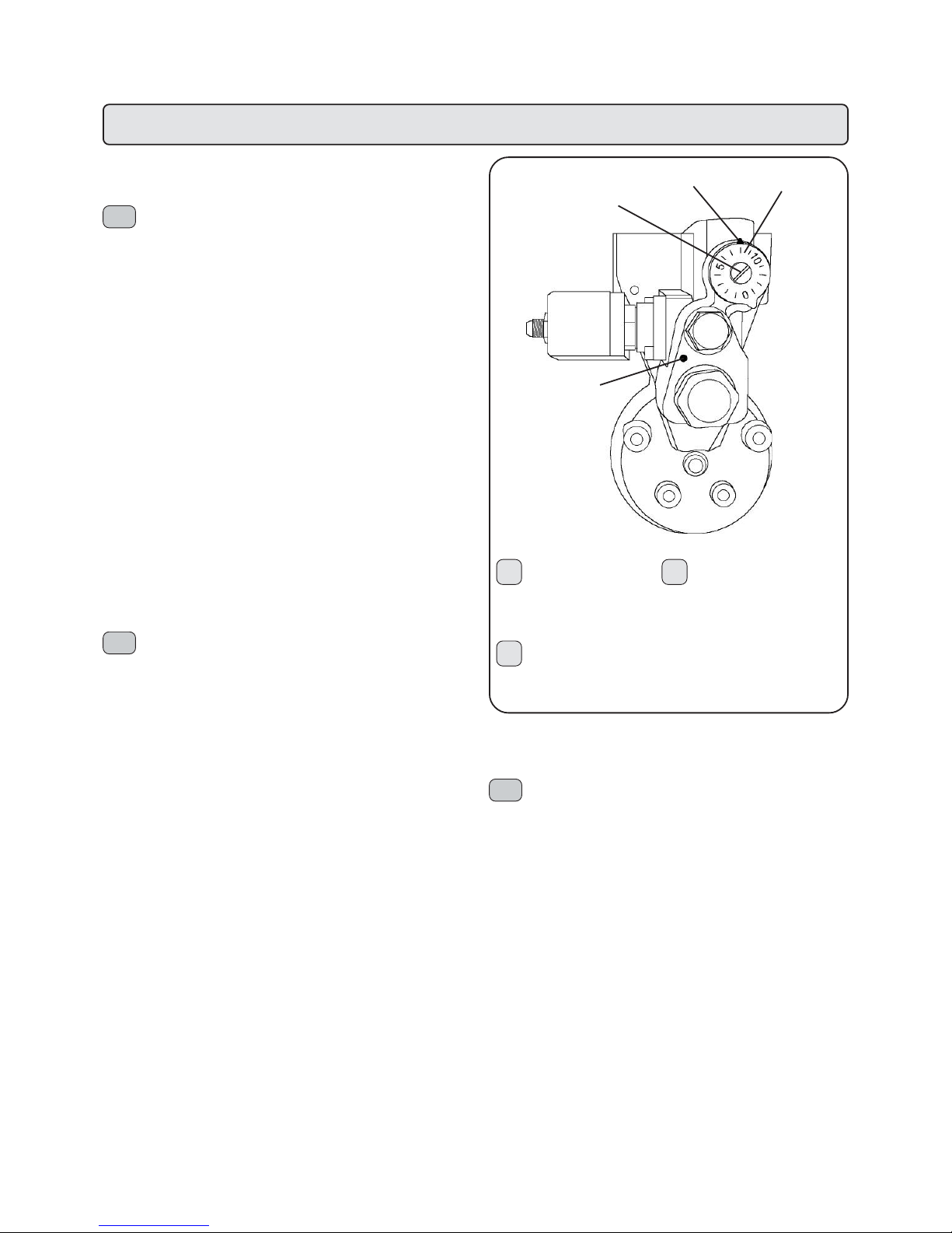
224
GROUP WITH TEMPERA TURE ADJUSTMENT VALVE
The E92 Elite coffee machine dispensing group has a temperature
adjustment valve that varies the heat of the group without having to use
the choke valve (see attached drawing). In this way it is possible to vary
the coffee water temperature from a minimum of approximately 70°C to a
maximum of approximately 107°C.
When the machine is cold it takes approximately 60 minutes for the
group to reach the set temperature; do not dispense water from the group
during this time.
Turn the valve to change the group temperature. The valve as a graded
scale divided into 15 sectors:
- To reduce the temperature: rotate the adjusting screw (2) clockwise
(low numbers).
- To increase the temperature: rotate the adjusting screw (2)
anticlockwise (high numbers).
When the adjusting screw is rotated, the group takes 10 minutes before
stabilizing into the new temperature.
N.B.: In the case of wrong operations, to reset the original conditions set
by Faema, close the adjusting screw (2) completely to 0. Then reposition
the screw to adjustment 8 of the ring nut
Regolazioni - Setting - Reglages - Einstellungen - Regulaciones - Regulações
2
1
4
3
1 Ghiera numerata
2 Vite di regolazione
3 Foro rilievo temperatura
4 Riferimento
GRUPPO CON VALVOLA DI REGOLAZIONE
TEMPERATURA
Il gruppo erogatore della macchina da caffè E92 Elite è stato dotato di
una valvola di regolazione temperatura, che permette di variare la termica
del gruppo senza dover intervenire sulla strozzatura (vedere dis. allegato).
In questo modo è possibile variare la temperatura dell' acqua per la
produzione del caffè da un minimo di 70°C circa, ad un massimo di
107°C circa.
Partendo da macchina fredda, prima che il gruppo si stabilisca alla
temperatura prestabilita occorre attendere circa 60 minuti (senza far
erogare acqua dal gruppo).
Per variare la temperatura del gruppo si interviene sulla valvola, dotata di
scala graduata suddivisa in 15 settori:
- per ridurre la temperatura: ruotare la vite di regolazione (2) in senso
orario (numeri bassi).
- per aumentare la temperatura: ruotare la vite di regolazione (2) in senso antiorario (numeri alti).
Ruotando la vite di regolazione, il gruppo impiega circa 10 minuti prima di
stabilizzarsi alla nuova temperatura.
N.B.: in caso di errate operazioni, per ripristinare le condizioni di partenza,
come fornite da Faema, chiudere tutta la vite di regolazione (2) fino al
punto di fermo 0, poi riposizionare la vite sulla regolazione 8 della ghiera
numerata.
1. Numbered ring nut
2. Adjusting screw
3. Temperature detection hole
4. Reference
GBI
1 Bague numérotée
2 Vis de réglage
3 Trou relevé de la température
4 Référence
F
GROUPE COMPOSE DE SOUPAPE DE REGLAGE DE
LA TEMPERATURE
Le groupe de débit de la machine à café E92 Elite a été doté d'une
soupape de réglage de la température qui permet de varier la thermique
du groupe sans avoir à intervenir sur l'étranglement (voir dessin en pièces
jointes).
De cette façon, il est possible de varier la température de l'eau pour la
production du café d'un minimum de 70°C environ à un maximum de
107°C environ.
En partant de la machine froide, avant que le groupe ne se stabilise à la
température préétablie, il faut attendre environ 60 minutes (sans faire
débiter d'eau du groupe).
Pour varier la température du groupe, on intervient sur la soupape, dotée
d'une échelle graduée, subdivisée en 15 secteurs:
- pour réduire la température: tourner la vis de réglage (2) dans le sens
des aiguilles d'une montre (nombres bas)
- pour augmenter la température; tourner la vis de réglage (2) dans le
sens contraire des aiguilles d'une montre (nombres élevés)
En tournant la vis de réglage , le groupe met environ 10 minutes avant de
se stabiliser à la nouvelle température.
N.B. Dans le cas d'opérations erronées, pour rétablir les conditions de
départ comme celles qui ont été fournies par Faema, fermer toute la vis
de réglage (2) jusqu'au point d'arrêt 0, puis replacer la vis sur le réglage 8
de la bague numérotée.
I
GB
F
Page 65
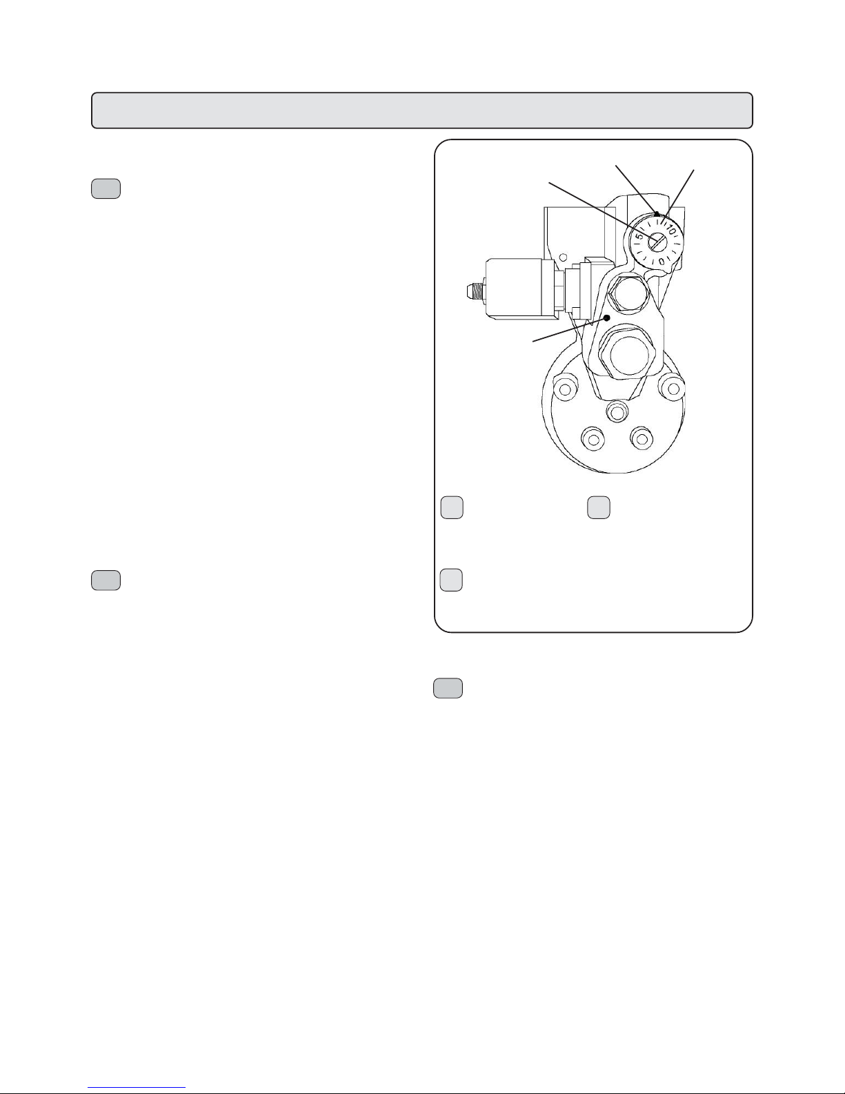
225
D
1 Virola numerada
2 Parafuso de regulação
3 Furo de detecção da temperatura
4 Referência
P
ABGABEEINHEIT MIT VENTIL ZUR TEMPERA TURREGELUNG
Die Abgabeeinheiten der Kaffeemaschinen der Baureihe E92 Elite sind
mit einem Ventil zur Temperaturregelung ausgestattet, über welches die
Temperatur der Einheit ohne Aktivierung der Drosselung verändert werden
kann (siehe beiliegende Zeichnung).
Auf diese Weise kann die Temperatur des zur Kaffeezubereitung
erforderlichen Wassers in einem Bereich zwischen ca. 70°C und 107°C
eingestellt werden.
Bei noch kalter Maschine muß vor Erreichen der programmierten
Temperatur zunächst etwa 60 Minuten abgewartet werden (ohne aus der
Abgabeeinheit Wasser austreten zu lassen).
Die Regelung der Betriebstemperatur der Abgabeeinheit erfolgt über das
Ventil, das mit einer in 15 Felder unterteilten Skala ausgestattet ist:
- Reduzierung der Betriebstemperatur: Drehen Sie die Regelschraube
(2) im Uhrzeigersinn (niedrige Werte);
- Steigerung der Betriebstemperatur: Drehen Sie die Regelschraube (2)
gegen den Uhrzeigersinn (hohe Werte).
Nach Einstellung der Regelschraube benötigt die Maschine etwa 10
Minuten, bis die neu eingestellte Temperatur erreicht ist.
Zu beachten: Um die Maschine im Fall von unbeabsichtigten Regelungen
auf die werkseitig von FAEMA eingestellten Ausgangssituationen
zurückzustellen, müssen Sie die Regelschraube (2) bis zum Nullpunkt
schließen und anschließend auf die auf dem Nummernkranz angegebene
Regelstufe 8 stellen.
GRUPO CON VÁLVULA DE REGULACIÓN TEMPERATURA
El grupo erogador de la máquina de café E92 Elite ha sido equipado con
una válvula de regulación de la temperatura que permite variar la
temperatura del grupo sin tener que intervenir en el estrechamiento (véase
diseño adjuntado).
De esta forma se puede variar la temperatura del agua para la producción
del café de un mínimo de unos 70°C a un máximo de unos 107°C.
Empezando con la máquina fría, antes de que el grupo se establezca a
la temperatura establecida, hay que esperar unos 60 minutos (sin dejar
erogar agua del grupo).
Para variar la temperatura del grupo se utiliza la válvula, provista de una
escala graduada dividida en 15 sectores:
- para reducir la temperatura: gire el perno de regulación (2) en sentido
horario (números bajos).
- para aumentar la temperatura: gire el perno de regulación (2) en sentido
antihorario (números altos);
Girando el perno de regulación, el grupo tarda unos 10 minutos antes de
estabilizarse en la nueva temperatura.
N.B.: en el caso de operaciones incorrectas, para restablecer las
condiciones de inicio, como son suministradas por Faema, cierre todos
los pernos de regulación (2) hasta el punto de parada 0 y luego coloque
el perno en la regulación 8 de la válvula numerada.
Regolazioni - Setting - Reglages - Einstellungen - Regulaciones - Regulações
2
1
4
3
1 Nummernkranz
2 Regelschraube
3 Öffnung zur
Temperaturermittlung
4 Bezugswert
1. Válvula numerada
2. Perno de regulación
3. Orificio para medir la
temperatura
4. Referencia
E
GRUPO COM VÁLVULA DE REGULAÇÃO DA TEMPERA TURA
O grupo de distribuição da máquina de café E92 Elite foi dotado de uma
válvula de regulação da temperatura, que permite variar a o interruptor
térmico do grupo sem ter que intervir sobre o estrangulamento (ver
desenho anexo).
Deste modo é possível variar a temperatura da água para a produção do
café, de um mínimo de cerca 70 °C até um máximo de cerca 107 °C.
Partindo da máquina fria, antes que o grupo se estabeleça à temperatura
pré-estabelecida, é necessário aguardar cerca de 60 minutos (sem deixar
distribuir água através do grupo).
Para variar a temperatura do grupo intervem-se sobre a válvula, dotada
de escala graduada, dividida em 15 sectores:
- para reduzir a temperatura: rodear o parafuso de regulação (2) em
sentido horário (números baixos).
- Para aumentar a temperatura: rodear o parafuso de regulação (2) em
sentido contrário aos ponteiros do relógio (números altos).
Rodeando o parafuso de regulação, o grupo emprega cerca 10 minutos
antes de se estabilizar na nova temperatura.
N.B.: em caso de operações erradas, para restabelecer as condições de
partida, como fornecidas pela Faema, fechar completamente o parafuso
de regulação (2) até ao ponto de paragem 0 e, a seguir, reposicionar o
parafuso sobre a regulação 8 da virola numerada.
D
E
P
Page 66

226
Regolazioni - Setting - Reglages - Einstellungen - Regulaciones - Regulações
REGULACIÓN DEL SENSOR DE LA TEMPERA TURA
NOTA: se tiene que realizar sólo en el caso de sustitución
del sensor o de la tarjeta electrónica (T).
Instalar el manómetro de control de la presión de la caldera en el tubo
del vapor.
Quitar el panel del lado derecho para acceder a la tarjeta electrónica
(T).
Pulse los interruptores (1) y (1a).
Esperar a que se apague el indicador luminoso de activación de las
resistencias (3).
Utilizar el trimmer (A) situado en la tarjeta electrónica (T) para que se
lea en el visualizador el mismo valor que el del manómetro.
GENAUE POSITIONIERUNG DES TEMPERATURFÜHLERS
Zu beachten: Die Positionierung des Temperaturfühler braucht nur
bei einem Austausch des Fühlers oder der Elektronikkarte
(T) vorgenommen werden.
Installieren Sie den Druckmesser zur Kontrolle des Heizkesseldrucks
auf dem Rohr zur Wasserdampfabgabe.
Abnehmen Sie das Seitenteil, um zur Elektronikkarte (T) zu gelangen
Drücken Sie die Tasten (1)und (1a).
Warten Sie ab, bis daß die Kontrolleuchte zur Zuschaltung der
Heizelemente (3) erlischt.
Stellen Sie den auf der Elektronikkarte (T) installierten Reger (A) so
ein; daß auf der Anzeige der auf dem Druckmesser abgelesene
Wert erscheint.
ALLINEAMENTO SENSORE DI TEMPERA TURA
N.B.: da eseguire solo nel caso di sostituzione del sensore
o della scheda elettronica (T).
Installare il manometro di controllo della pressione caldaia sulla lancia
vapore.
Accedere alla scheda elettronica (T) situata sotto il pannello laterale
destro.
Premere gli interruttori (1) e (1a).
Attendere lo spegnimento della spia inserimento resistenze (3).
Agire sul trimmer (A) posto sulla scheda elettronica (T) affinchè sul
display si legga lo stesso valore riscontrato sul manometro.
TEMPERA TURE SENSOR ALIGNMENT
N.B. To be performed only upon substitution of the sensor
or the electronic card (T).
Install the boiler pressure control gauge on the steam nozzle.
Remove the right side panel to access the electronic card (T).
Press switches (1) and (1a).
Wait until the heating element insertion pilot light (3) switches off.
Adjust the trimmer (A) located on the electronic card (T) until the
same display reads the same value as that of the gauge.
ALIGNEMENT DU CAPTEUR DE TEMPERATURE
N.B. : à n’effectuer qu’eu cas de remplacement du capteur ou de la
fiche électronique (T).
Installer le manomètre de contrôle de la pression de la chaudière sur
la lance de la vapeur.
Enlevez le panneau du côté droit pour accéder à la carte électronique
(T).
Brancher les interrupteurs (1) et (1a).
Attendre que le témoin lumineux introduction des résistances (3)
s’éteigne.
Agir sur le trimmer (A) plaçé sur la fiche électronique (T) de manière
à pouvoir lire sur le display la même valeur qui apparait sur le
manomètre.
A
ALINHAMENTO DO SENSOR DE TEMPERA TURA
N.B.: a executar apenas no caso de substituição do sensor
ou da ficha electrónica (T).
Instalar o manómetro de controle da pressão da caldeira sobre a
lança vapor.
Remover o painel do lado direito para aceder ao ficha electrónica
(T).
Carregar nos interruptores (1) e (1a).
Aguardar a desligação do indicador de inserimento resistência (3).
Utilizar o trimmer (A) colocado na ficha electrónica (T) para que no
mostrador se leia o mesmo valor detectado sobre o manómetro.
T
I GB
F
D
E
P
Page 67

227
Regolazioni - Setting - Reglages - Einstellungen - Regulaciones - Regulações
DIP-SWITCH CPU
Attenzione!
Il cambiamento di posizione dei Dip-Switch deve essere
effettuato RIGOROSAMENTE a macchina SPENTA.
Nelle condizioni standard il Dip-Switch 8 = ON.
Estrarre il cassetto elettrico operando come indicato nel capitolo "SMONTAGGIO".
Agendo sui Dip-Switch (D) si attivano le seguenti funzioni:
- DIP 1 =OFF - ON inserimento dati standard (*)
- DIP 2 = OFF
- DIP 3 = OFF - ON simulazione chiave tecnico
- DIP 4 = OFF - ON contabilità
- DIP 5 = OFF - ON abilita sequenza tasti per ingresso in programmazione
- DIP 6 = OFF
- DIP 7 = OFF
- DIP 8 = ON
(*) Al termine delle operazioni di inserimento dati standard, riportare il DIP
1 sulla posizione OFF.
CPU DIP-SWITCH
CAUTION!
When changing the position of the Dip-Switch, the machine
MUST BE SWITCHED OFF .
Under standard conditions, the dip-switch 8 = ON.
Remove the electric drawer as indicated in the chapter “DISASSEMBLY”.
The dip-switches (D) have the following functions:
- DIP 1 = OFF - ON Input of standard data (*)
- DIP 2 = OFF
- DIP 3 = OFF - ON Simulation of engineer’s key
- DIP 4 = OFF - ON Bookkeeping
- DIP 5 = OFF - ON allows keys sequence to enter programming
- DIP 6 = OFF
- DIP 7 = OFF
- DIP 8 = ON
(*) Upon completion of the standard data input operations, position DIP 1
to OFF again.
DIP-SWITCH CPU
Attention !
Le changement de position des Dip-Switch doit être
RIGOUREUSEMENT effectué lorsque la machine est ETEINTE.
En phase de standard, le Dip-Switch 8 = ON.
Enlever le tiroir électrique en suivant les instructions reportées au chapitre
“DEMONTAGE”.
Utiliser les Dip-Switch (D) pour activer les fonctions suivante:
- DIP 1 = OFF - ON introduction informations standard (*)
- DIP 2 = OFF
- DIP 3 = OFF - ON simulation clef technique
- DIP 4 = OFF - ON comptabilité
- DIP 5 = OFF - ON habilite la séquence de touches pour entrer en
programmation
- DIP 6 = OFF
- DIP 7 = OFF
- DIP 8 = ON
(*) à la fin des opérations d’introduction des informations standard,
remettre le DIP 1 sur la position OFF.
DIP-SWITCH-SCHALTER CPU
Achtung:
Die Verstellung der Dip-Switch-Schalter darf nur bei
ABGESCHALTETER Maschine vorgenommen werden!
Bei normalen Betriebsbedingungen: Dip-Switch-Schalter 8 = ON.
Ziehen Sie den Einschub der elektrischen Baugruppen aus dem Gerät,
indem Sie wie im Kapitel ‘DEMONTAGE’ beschrieben vorgehen.
Nachstehend werden die Funktionen bei entsprechender Einstellung der
Dip-Switch-Schalter (D) aufgeführt:
- DIP 1 = OFF - ON Eingabe Standarddaten (*)
- DIP 2 = OFF
- DIP 3 = OFF - ON Simulation Monteurschlüssel
- DIP 4 = OFF - ON Buchführung
- DIP 5 = OFF - ON ermächtigen Sie die Anschlagsequenz,
um in Programmierung hineinzugehen
- DIP 6 = OFF
- DIP 7 = OFF
- DIP 8 = ON
(*) Nach Abschluß der Eingabe der Standarddaten muß der Dip-SwitchSchalter 1 auf OFF zurückgestellt werden.
DIP-SWITCH CPU
¡Atención!
El cambio de posición de los Dip-switch (O) se tiene
que efectuar RIGUROSAMENTE con la máquina APAGADA.
En condiciones estándares el Dip-switch 8 = ON.
Quitar la caja eléctrica como se ha indicado en el apartado
“DESMONTAJE”.
Por medio de los Dip-Switch (D) se activan las siguientes funciones:
- DIP 1 = OFF - ON introducción datos estándares (*)
- DIP 2 = OFF
- DIP 3 = OFF - ON simulación llave técnico
- DIP 4 = OFF - ON contabilidad
- DIP 5 = OFF - ON habilita la secuencia de teclas para entrar
en programación
- DIP 6 = OFF
- DIP 7 = OFF
- DIP 8 = ON
(*) Al final de las operaciones de introducción datos estándares,
restablecer el DIP 1 a la posición OFF.
DIP-SWITCH CPU
Atenção!
A mudança de posição dos Dip-Switch deverá ser
efectuada RIGOROSAMENTE com a máquina DESLIGADA.
Nas condições standard o Dip-Switch 8 = ON.
Extrair a gaveta eléctrica, actuando conforme indicado no capítulo
"DESMONTAGEM".
Actuando nos Dip-Switch (D) activam-se as funções a seguir
indicadas:
- DIP 1 = OFF - ON introdução dados standard (*)
- DIP 2 = OFF
- DIP 3 = OFF - ON simulação chave técnico
- DIP 4 = OFF - ON contabilidade
- DIP 5 = OFF - ON habilita a sequência das teclas para
entrar em programação
- DIP 6 = OFF
- DIP 7 = OFF
- DIP 8 = ON
(*) No fim das operações de introdução dos dados standard, recolocar
o DIP 1 na posição OFF.
D
I
GB
F
E
D
P
Page 68
228
Regolazioni - Setting - Reglages - Einstellungen - Regulaciones - Regulações
REGOLAZIONE CONTRASTO DISPLA Y
Estrarre il cassetto elettrico operando come indicato nel capitolo
"SMONTAGGIO".
Agire sul trimmer (A) posto sulla scheda elettronica affinchè sul
display si leggano i messaggi in modo chiaro.
DISPLA Y CONTRAST SETTING
Remove the electric drawer as indicated in the chapter
“DISASSEMBLY”*.
Adjust trimmer (A) located on the electronic card until the messages
may be clearly read on the display.
REGLAGE DU CONTRASTE DU DISPLA Y
Enlever le tiroir électrique en suivant les instructions reportées au
chapitre “DEMONTAGE”.
Agir sur le trimmer (A) plaçé sur la fiche électronique afin de pouvoir
lire clairement les messages qui apparaissent sur le display.
EINSTELLUNG DES KONTRASTS DER ANZEIGE
Ziehen Sie den Einschub der elektrischen Baugruppen aus dem Gerät,
indem Sie wie im Kapitel ‘DEMONTAGE’ beschrieben vorgehen.
Stellen Sie den auf der Elektronikkarte installierten Reger (A) so ein,
daß die Meldungen auf der Anzeige in gutem Kontrast abgebildet
werden und gut abgelesen werden können.
REGULACIÓN DEL CONTRASTE DEL VISUALIZADOR
Quitar la caja eléctrica como se indica en el apartado “DESMONT AJE”.
Utilizar el trimmer (A) situado en la tarjeta electrónica para que se
lean los mensajes claramente en el visualizador.
REGULACIÓN DEL CONTRASTE DEL VISUALIZADOR
Extrair a gaveta eléctrica actuando conforme indicado no capítulo
"DESMONTAGEM".
Utilizar o trimmer (A) colocado sobre a ficha electrónica para que
sobre o mostrador se leiam as mensagens de modo claro.
A
COLLEGAMENTO ELETTRICO
∆∆
∆∆
∆
In questo tipo di collegamento (∆) occorre verificare sulla scheda
elettronica l'esatta disposizione dei fili blu.
∆∆
∆∆
∆
ELECTRIC CONNECTION
In this type of connection (∆) needs to be check the right position of
the blue wires on the electronic card.
BRANCHEMENT ELECTRIQUE
∆∆
∆∆
∆
Dans ce type de raccordement (∆) il faut vérifier sur la fiche
électronique l'exacte disposition des fils bleus.
STROMANSCHLUSS
∆∆
∆∆
∆
In dieser Art von Verbindung (∆) man muß auf der Elektronikkarte die
genaue Bestimmung der blauen Fäden prüfen.
CONEXION ELECTRICA
∆∆
∆∆
∆
En este tipo de conexión (∆) es necesario comprobar sobre la tarjeta
electrónica la exacta disposición de los hilos azules.
LIGAÇÃO ELÉCTRICA
∆∆
∆∆
∆
Neste tipo de conexão (∆) é necessário verificar sobre a ficha
electrónica a exacta disposição dos fios azuis.
I
GB
F
D
E
P
BLU
BLUE
BLEU
BLAU
AZUL
AZUL
I
GB
F
D
E
P
Page 69
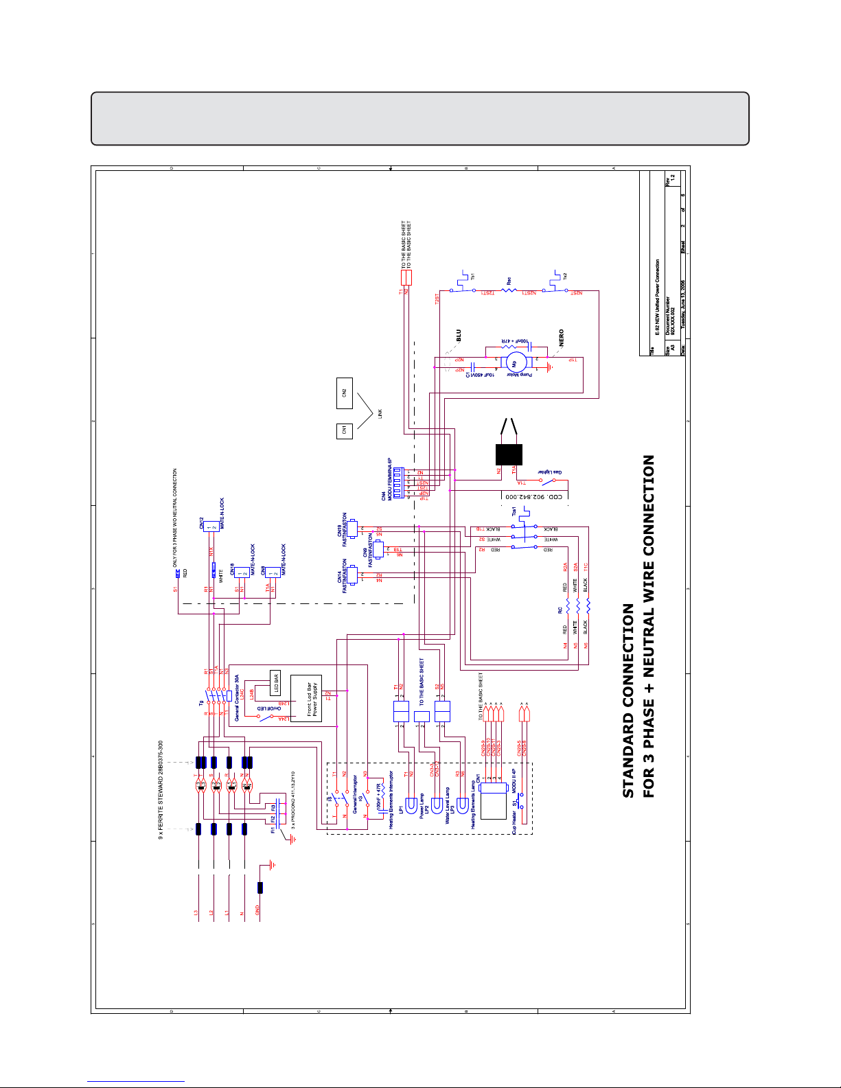
229
Schema elettrico - Wiring diagram - Schéma éléctrique Elektrischer Shaltplan - Esquema electrico - Esquema eléctrico
Page 70
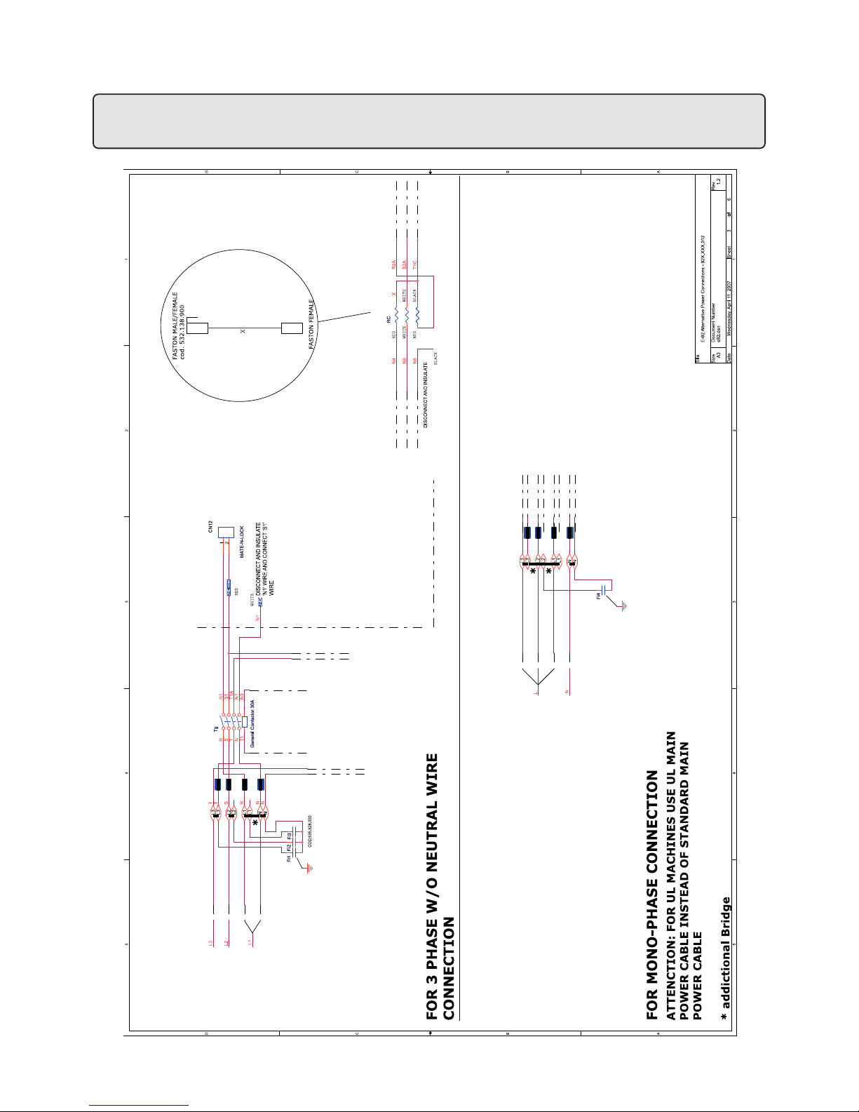
230
Schema elettrico - Wiring diagram - Schéma éléctrique Elektrischer Shaltplan - Esquema electrico - Esquema eléctrico
Page 71
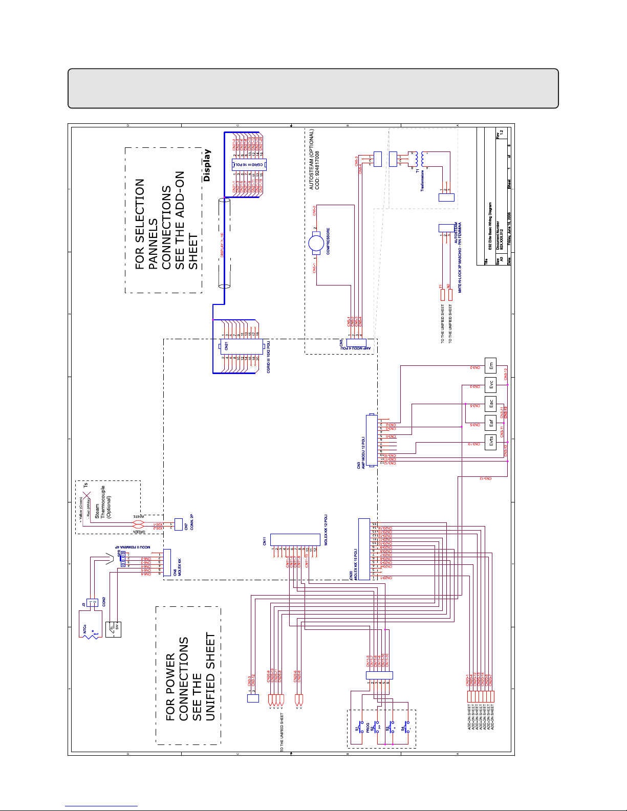
231
Schema elettrico - Wiring diagram - Schéma éléctrique Elektrischer Shaltplan - Esquema electrico - Esquema eléctrico
Page 72
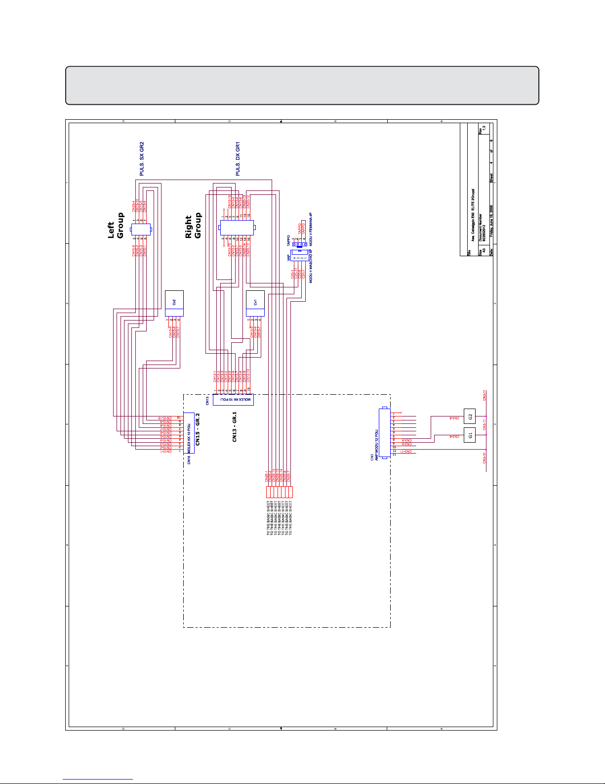
232
Schema elettrico - Wiring diagram - Schéma éléctrique Elektrischer Shaltplan - Esquema electrico - Esquema eléctrico
Page 73
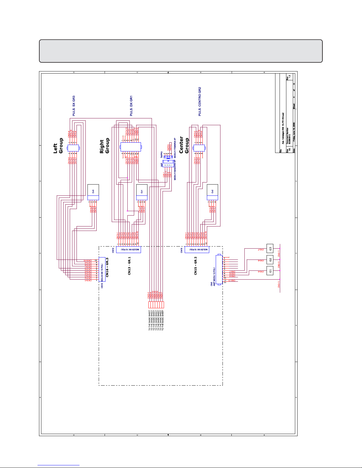
233
Schema elettrico - Wiring diagram - Schéma éléctrique Elektrischer Shaltplan - Esquema electrico - Esquema eléctrico
Page 74
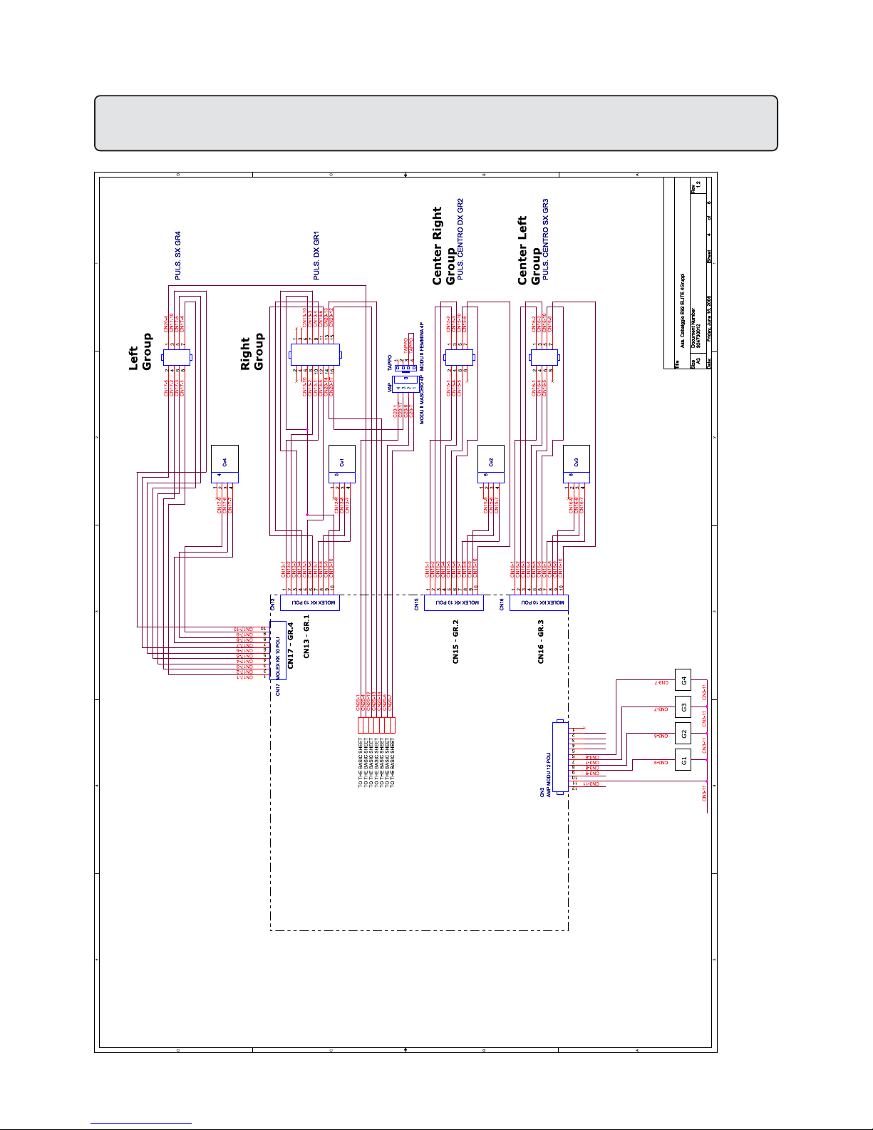
234
Schema elettrico - Wiring diagram - Schéma éléctrique Elektrischer Shaltplan - Esquema electrico - Esquema eléctrico
Page 75
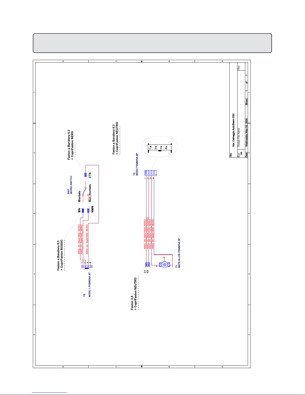
235
Schema elettrico - Wiring diagram - Schéma éléctrique Elektrischer Shaltplan - Esquema electrico - Esquema eléctrico
Page 76
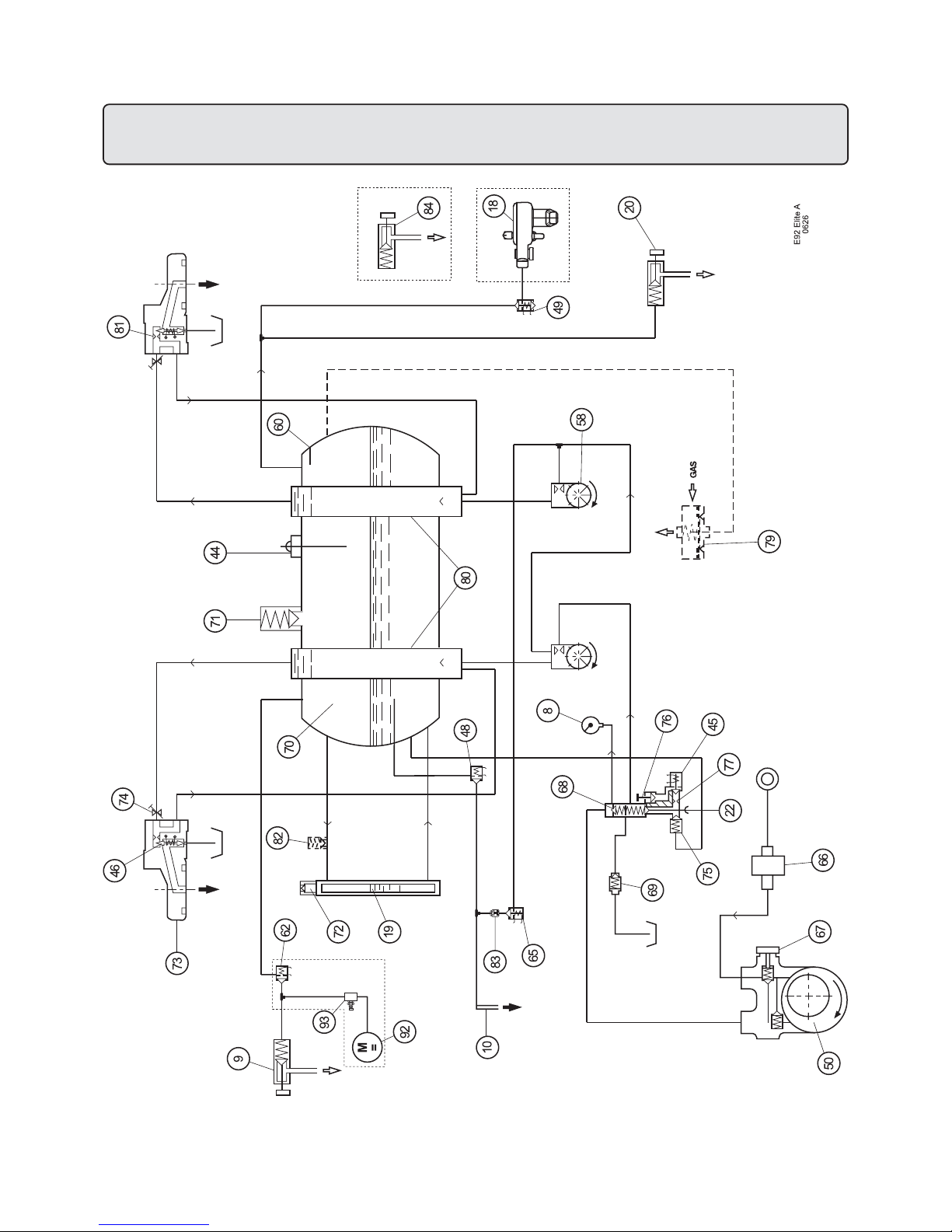
236
Circuito idraulico - Hydraulic circuit - Circuit hydraulique
Hydraulikplan - Circuito hidraulico - Circuito hidráulico
Page 77

237
Circuito idraulico - Hydraulic circuit - Circuit hydraulique
Hydraulikplan - Circuito hidraulico - Circuito hidráulico
LEGENDA
8 = Manometro rete/pompa
9 = Lancia destra erogazione vapore
10 = Lancia erogazione acqua calda
18 = Cappuccinatore
19 = Indicatore livello ottico acqua in
caldaia
20 = Lancia sinistra erogazione vapore
22 = Leva riempimento manuale acqua in
caldaia
44 = Sonda autolivello
45 = Elettrovalvola livello
46 = Elettrovalvola gruppo
48 = Elettrovalvola acqua calda
49 = Elettrovalvola cappuccinatore
(vapore*)
50 = Motore pompa
58 = Turbinetta
60 = Sensore temperatura caldaia
62 = Elettrovalvola vapore
65 = Elettrovalvola acqua fredda
66 = Filtro per pompa
67 = Regolazione pressione pompa
68 = Valvola non ritorno scambiatori
69 = Valvola espansione
70 = Caldaia
71 = Valvola di sicurezza
72 = Valvola anti-depressione
73 = Gruppo erogatore
74 = Strozzatura gruppo
75 = Valvola non ritorno caldaia
76 = Perno esclusione elettrovalvola 45
77 = Strozzatura autolivello
79 = Autoregolatore gas (*)
80 = Scambiatori di calore
81 = Iniettore gruppo
82 = Valvola di sicurezza (solo Spagna)
83 = Iniettore
84 = 2° Lancia sinistra erogazione vapore (*)
92 = Motore compressore *
93 = Elettrovalvola Autosteam *
I componenti -*- sono applicati solo su alcune
configurazioni di prodotti.
LEGEND
8 = Pump pressure gauge
9 = Right steam dispensing nozzle
10 = Hot water dispensing nozzle
18 = Cappuccino maker
19 = Optical indicator for hot water in boiler
20 = Left steam dispensing nozzle
22 = Manual lever for boiler fill
44 = Automatic level probe
45 = Level solenoid valve
46 = Group solenoid valve
48 = Hot water solenoid valve
49 = Cappuccino solenoid valve (steam*)
50 = Pump motor
58 = Turbine
60 = Boiler temperature sensor
62 = Steam solenoid valve
65 = Cold water solenoid valve
66 = Pump filter
67 = Pump pressure regulator
68 = Non return valve (heat exch.)
69 = Expansion valve
70 = Boiler
71 = Safety valve
72 = Vacuum release valve
73 = Coffee dispenser group
74 = Dispenser neck
75 = Boiler non return valve
76 = Pin-tap for solenoid valve 45
77 = Automatic filling neck
79 = Gas autoregulator (*)
80 = Heat exchangers
81 = Dispenser group iniector
82 = Safety valve (Spain only)
83 = Iniector
84 =2nd left steam dispensing nozzle (*)
92 = Motor compressor *
93 = Autosteam solenoid valve *
Items marked - * - are fitted in some product
configurations only.
LEGENDA
8 = Manomètre réseau/pompe
9 = Lance droite débit vapeur
10 = Lance débit eau chaude
18 = Cappuccinateur
19 = Indicateur visuel du niveau de l’eau
dans la chaudière
20 = Lance gauche débit vapeur
22 = Levier remplissage manuel de l’eau
dans la chaudière
44 = Sonde niveau automatique
45 = Electrovalve niveau
46 = Electrovalve groupe
48 = Electrovalve eau chaude
49 = Electrovalve cappuccinateur (vapour*)
50 = Moteur pompe
58 = Petite turbine
60 = Capteur température chaudière
62 = Electrovalve vapeur
65 = Electrovalve eau froide
66 = Filtre pour la pompe
67 = Réglage de la pression de la pompe
68 = Valve non-retour des échangeurs
69 = Valve d’expansion
70 = Chaudière
71 = Valve de sécurité
72 = Valve anti-dépression
73 = Groupe de débit
74 = Etranglement du groupe
75 = Valve de non retour de la chaudière
76 = Pivot d’exclusion de l’électrovalve 45
77 = Etranglement niveau automatique
79 = Autorégulateur de gaz (*)
80 = Echangeurs de chaleur
81 = Injecteur de groupe
82 = Valve de sécurité (uniquement pour
l’Espagne)
83 = Injecteur
84 = 2° Lance gauche débit vapeur (*)
92 = Moteur comprimeur *
93 = Electrovanne Autosteam *
Les détails - * - ne sont appliqués qu'à certaines
configurations de produit.
I GB F
Page 78

238
Circuito idraulico - Hydraulic circuit - Circuit hydraulique
Hydraulikplan - Circuito hidraulico - Circuito hidráulico
LEGENDE
8 = Druckmesser Pumpe
9 = rechter Strahler Dampfabgabe
10 = Strahler Heißwasserabgabe
18 = Cappuccinozubereitung
19 = Optische Standanzeige Wasserstand in
Heizkessel
20 = linker Strahler Dampfabgabe
22 = Hebel zur manuellen Füllung Wasser in
Heizkessel
44 = Fühler automatische Standanzeige
45 = Magnetventil Stand
46 = Magnetventil Abgabeeinheit
48 = Magnetventil Heißwasserabgabe
49 = Magnetventil Cappuccino-Zubereitung
(Dampf*)
50 = Pumpenmotor
58 = Turbine
60 = Fühler Temperatur Heizkessel
62 = Dampf Magnetventil
65 = Kaltwasser Magnetventil
66 = Pumpenfilter
67 = Einstellung Pumpendruck
68 = Rückschlagventil Wärmetauscher
69 = Überlaufventil
70 = Heizkessel
71 = Sicherheitsventil
72 = Entlastungsventil
73 = Abgabeeinheit
74 = Drossler Abgabeeinheit
75 = Rückschlagventil Heizkessel
76 = Sperrstift Magnetventil 45
77 = Drosselung automatische Einfüllung
79 = Selbstreglung Gas (*)
80 = Wärmetauscher
81 = Injektor
82 = Sicherheitsventil (nur für Spanien)
83 = Injektor
84 = 2. linker Strahler Dampfabgabe (*)
92 = Motor Kompressor *
93 = Magnetventil Autosteam *
Die mit - * - gekennzeichneten Komponenten
sind nur in bestimmten Modellen installiert.
LEYENDA
8 = Manómetro red/bomba
9 = Tubo derecho erogación vapor
10 = Tubo erogación agua caliente
18 = Cappuccinador
19 = Indicador nivel óptico agua en la
caldera
20 = Tubo izquierda erogación vapor
22 = Palanca llenado manual agua en la
caldera
44 = Sonda autonivel
45 = Electroválvula nivel
46 = Electroválvula grupo 2
48 = Electroválvula agua caliente
49 = Electroválvula cappuccinador (vapor*)
50 = Motor Bomba
58 = Turbina
60 = Sensor temperatura caldera
62 = Electroválvula vapor
65 = Electroválvula agua fria
66 = Filtro para bomba
67 = Regulación presión bomba
68 = Válvula de retención cambiadores
69 = Válvula expansión
70 = Caldera
71 = Válvula de seguridad
72 = Válvula anti-depresión
73 = Grupo erogador
74 = Estrangulación grupo
75 = Válvula de retención caldera
76 = Perno exclusión electroválvula 45
77 = Estrangulación autonivel
79 = Autorregulador gas (*)
80 = Cambiadores de calor
81 = Inyector grupo
82 = Válvula de seguridad (sólo España)
83 = Inyector
84 = 2° Tubo izquierdo erogación vapor (*)
92 = Motor compressor *
93 = Electroválvula Autosteam *
Los detallos -*- se pueden aplicar sólo en
algunas configuraciones del producto.
LEGENDA
8 = Manómetro rede/bomba
9 = Lança direita de distribuição do vapor
10 = Lança de distribuição da água quente
18 = Preparador de cappuccino
19 = Indicador de nível óptico de água na
caldeira
20 = Lança esquerda de distribuição do
vapor
22 = Alavanca de enchimento manual da
água na caldeira
44 = Sonda de auto-nível
45 = Electro-válvula nível
46 = Electro-válvula grupo
48 = Electro-válvula da água quente
49 = Electro-válvula do preparador de
cappuccino (vapor*)
50 = Motor da bomba
58 = Turbina
60 = Sensor da temperatura da caldeira
62 = Electro-válvula do vapor
65 = Electro-válvula da água fria
66 = Filtro para bomba
67 = Regulação da pressão da bomba
68 = Válvula de não retorno dos
permutadores
69 = Válvula de expansão
70 = Caldeira
71 = Válvula de segurança
72 = Válvula anti-depressão
73 = Grupo de distribuição
74 = Estrangulamento do grupo
75 = Válvula de não retorno da caldeira
76 = Pino de exclusão da electro-válvula 45
77 = Estrangulamento auto-nível
79 = Auto-regulador do gás (*)
80 = Permutadores de calor
81 = Injector do grupo
82 = Válvula de segurança (só para
Espanha)
83 = Injector
84 =2a Lança esquerda de distribuição do
vapor (*)
92 = Motor compressor *
93 = Electro-válvula Autosteam *
Os componentes “*“ – são aplicados apenas
sobre algumas configurações de produtos
D E P
Page 79

239
GRUPPO CIMBALI S.p.A.
Via A. Manzoni, 17
20082 Binasco
(MI) Italy
Tel. ..39 2 90.04.91 / 90.04.81
Fax ..39 2 90.54.818 / 90048486
www.faema.it
GRUPPO CIMBALI si riserva il diritto di apportare
cambiamenti all'equipaggiamento della macchina a
seconda delle esigenze di singoli Paesi e di effettuare
modifiche dovute agli avanzamenti del progresso
tecnico.
Nessuna parte di questa pubblicazione può essere
usata, copiata o pubblicata senza il permesso scritto
di GRUPPO CIMBALI S.p.A.
© Copyright by GRUPPO CIMBALI S.p.A., Milano
Tutti i diritti riservati
GRUPPO CIMBALI S.p.A.
Via A. Manzoni, 17
20082 Binasco
(MI) Italy
Tel. ..39 2 90.04.91 / 90.04.81
Fax ..39 2 90.54.818 / 90048486
www.faema.it
GRUPPO CIMBALI reserves the right to make changes
to the machines in accordance with the needs of
individual countries and on the basis of technological
progresses.
This publication may not, either in whole or in part, be
used, copied or published without the written
authorisation of
GRUPPO CIMBALI S.p.A.
© Copyright by GRUPPO CIMBALI S.p.A., Milan, Italy
All rights reserved
GRUPPO CIMBALI S.p.A.
Via A. Manzoni, 17
20082 Binasco
(MI) Italy
Tel. ..39 2 90.04.91 / 90.04.81
Fax ..39 2 90.54.818 / 90048486
www.faema.it
GRUPPO CIMBALI behält sich vor, Änderungen der
Maschine entsprechend den spezifischen nationalen
Gegebenheiten sowie entsprechend dem Fortschritt
der Technik vornehmen zu können.
Die vorliegende Veröffentlichung darf in keinen Teilen
ohne entsprechende Genehmigung der Firma GRUPPO CIMBALI S.p.A. vervielfältigt, kopiert oder veröffentlicht
werden.
© Copyright by GRUPPO CIMBALI S.p.A., Milano
Alle Rechte vorbehalten
GRUPPO CIMBALI S.p.A.
Via A. Manzoni, 17
20082 Binasco
(MI) Italy
Tel. ..39 2 90.04.91 / 90.04.81
Fax ..39 2 90.54.818 / 90048486
www.faema.it
La société GRUPPO CIMBALI se réserve le droit
d'apporter des changements à l'équipement de la
machine selon les exigences des pays, et d'effectuer
des modifications dûes aux avancements du progrès
technique.
Aucune partie de cette publication ne peut être utilisée,
copiée ou publiée sans l'autorisation écrite de GRUPPO CIMBALI S.p.A.
© Copyright by GRUPPO CIMBALI S.p.A., Milano
Touts droits réservés
GRUPPO CIMBALI S.p.A.
Via A. Manzoni, 17
20082 Binasco
(MI) Italy
Tel. ..39 2 90.04.91 / 90.04.81
Fax ..39 2 90.54.818 / 90048486
www.faema.it
GRUPPO CIMBALI reserva-se o direito de modificar o
equipamento da máquina segundo as exigências de
cada País e efectuar alterações devidas aos avanços
do progresso tecnológico.
Nenhuma parte desta publicação poderá ser utilizada,
copiada ou publicada sem autorização escrita de
GRUPPO CIMBALI S.p.A.
© Copyright by GRUPPO CIMBALI S.p.A., Milano
Todos os direitos são reservados
GRUPPO CIMBALI S.p.A.
Via A. Manzoni, 17
20082 Binasco
(MI) Italy
Tel. ..39 2 90.04.91 / 90.04.81
Fax ..39 2 90.54.818 / 90048486
www.faema.it
GRUPPO CIMBALI se reserva el derecho de aportar
cambios al equipamiento de la máquina según las
exigencias de cada uno de los países y de realizar
modificaciones debidas a los desarrollos del progresso
técnico.
Ninguna parte de esta publicación se puede usar, copiar o publicar sin el permiso escrito de GRUPPO
CIMBALI S.p.A.
© Copyright by GRUPPO CIMBALI S.p.A., Milán
Todos los derechos están reservados
I GB
F D
E P
Page 80

240
FAEMA e o "SERVICE LINE"
O Serviço de Assistência de empresa FAEMA, com a finalidade de aconselhar os Clientes na escolha dos produtos para a
melhor utilização da máquina de café, apresenta a linha:
ECO LINE - Produtos para a limpeza
A) 4991-134458 líquido para o kit cappuccino;
B) 4991-134682 en pó para os grupos, manípulo dos filtros, chávenas de café;
C) 4991-134681 carteiras para os grupos, manípulo dos filtros, chávenas de café;
D) 4991-134683 pastilhas para os grupos das máquinas superautomáticas.
Para encomendar, indicar o número de código ao seu Concessionário.
FAEMA y el "SERVICE LINE"
Con el deseo de facilitar a los Srs. CLIENTES la selección de los productos para el uso correcto de la máquina de café, el
servicio de asistencia de la sociedad FAEMA les muestra la linea:
ECO LINE - Productos para la limpieza
A) 4991-134458 líquido para los cappuccinadores;
B) 4991-134682 en polvos para los equipos, los portafiltros, las tazas de café;
C) 4991-134681 en sobres para los equipos, los portafiltros, las tazas de café;
D) 4991-134683 en pastillas para los equipos de las máquinas superautomáticas.
Para los pedidos, envío el número de código a su Concesionario.
FAEMA und die "SERVICE LINE"
Mit der Absicht dem Kunden bei der Produktwahl für den bestmöglichen Gebrauch der Kaffeemaschine beizustehen, weist der
Kundendienst der FAEMA Gesellschaft auf folgende Produktlinie hin:
ECO LINE - Produkte für die Säuberung
A) 4991-134458 Flüssig für die Cappuccino-Bereiter;
B) 4991-134682 in Pulverform für die Gruppen, die Filterhalter, die Kaffeetassen;
C) 4991-134681 Tüten für die Gruppen, die Filterhalter, die Kaffeetassen;
D) 4991-134683 Tabletten für die Kaffeegruppen der vollautomat Maschinen.
Für eine Bestellung bitte dem Vertreter die Katalog-Nr. angeben.
FAEMA e il "SERVICE LINE"
Il servizio assistenza della società FAEMA, nell'intento di essere vicino ai SIGG. Clienti nella scelta dei prodotti per il miglior
utilizzo della macchina da caffè, visualizza la linea:
ECO LINE - Prodotti per la pulizia
A) 4991-134458 liquido per i cappuccinatori;
B)4991-134682 in polvere per i gruppi, i portafiltri, le tazze da caffè;
C)4991-134681 bustine per i gruppi, i portafiltri, le tazze da caffè;
D)4991-134683 pastiglie per i gruppi nelle macchine superautomatiche.
Per ordinare trasmettete il numero di codice al Vs. Concessionario.
FAEMA and the "SERVICE LINE"
The FAEMA Company's client service, the aim of which is to assure top coffee-machine performance for its clients at all times,
also makes available its ECO LINE, a series of specific cleaning products expressly designed for this purpose.
ECO LINE - Cleaning products
A) For cappuccino makers in liquid form 4991-134458;
B) For dispensers, filter-holders, coffee cups in powder form 4991-134682;
C) For dispensers, filter-holders, coffee cups in small envelops 4991-134681;
D) For superautomatic-machine dispensers in tablet form 4991-134683.
Order directly from your local distributor and refer to the particular item you require by its number, as shown above.
FAEMA et la "SERVICE LINE"
La service d'assistance de la société FAEMA, dans l'intention d'être à côté de ses clients, dans le choix des produits et en vue
d'une meilleure utilisation de la machine à café, propose la ligne:
ECO LINE - Produits de nettoyage
A) 4991-134458 liquide pour les fouettes-lait;
B) 4991-134682 en poudre pour les groupes, les porte-filtre, les tasses à café;
C) 4991-134681 sachets pour les groupes, les porte-filtre, les tasses à café;
D) 4991-134683 pastilles pour les groupes des machines tout-auto.
Pour commander, transmettre le numéro de code à votre concessionnaire.
SERVICE LINE
I
GB
F
D
E
P
 Loading...