

Page 1
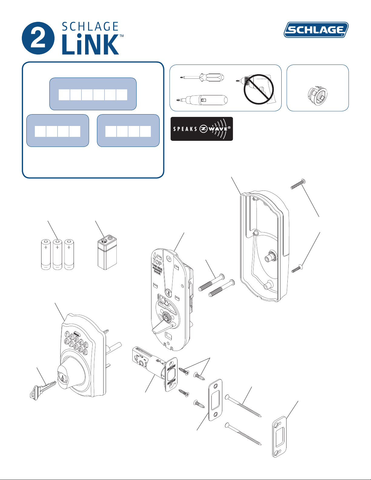
BE369 Deadbolt
Installation Instructions
Important Information
Lock Programming Code
six (6) digits
User Code A
four (4) digits
Web Support: part2.schlage.com
Customer Service: (877) 288-7707
AA batteries
9V battery
User Code B
four (4) digits
Baseplate
Alternate
Faceplate
O
Cover
Cover screws
Key
Keypad
Bolt
Baseplate
screws
Latch/strike
screws
Reinforcement
screws
Reinforcement
Plate
Strike
Page 2
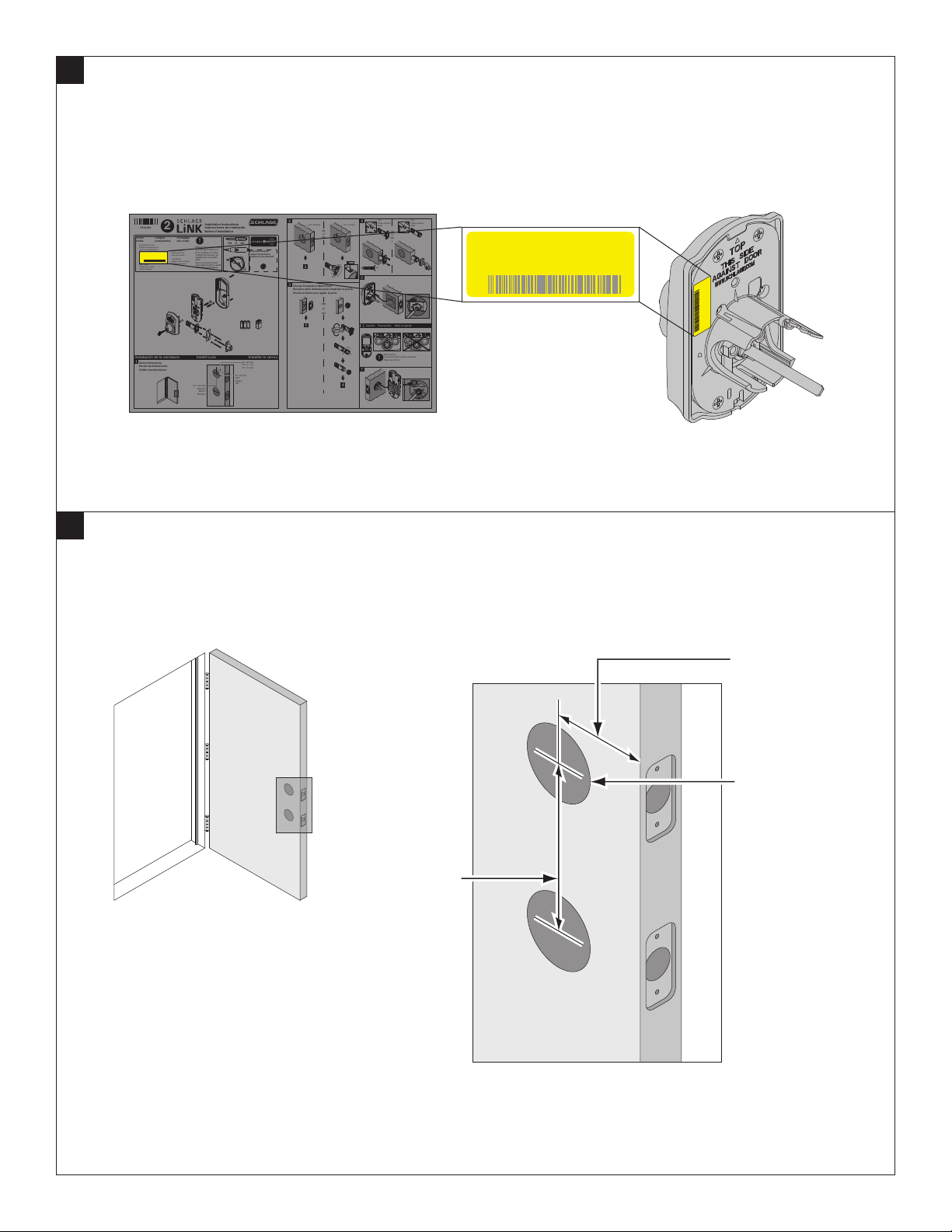
1
Locate Programming Code and Preset User Codes
The programming code and the preset user codes are printed on the yellow stickers located on the back of the
keypad and on the installation sheet that came in the box. Write these codes in the space provided on the first page.
Top
P515-861
Preset
Codes
Programming Code
Código de programación
Code de programmation
Prog Code XXXXXX
User Code A XXXX
User Code B XXXX
User Codes
Códigos de usuario
Codes utilisateur
1
Check Dimensions
Revise las dimensiones
Vérifier les dimensions
(FCC ID: P2GXXXXX)
XXXXX
SN XXXXXXXXX
Códigos
preajustados
2
Préréglage
des codes
Serial Number
Número de serie
Numéro de série
Lock Model
Modelo de la cerradura
Modèle de serrure
Installation Instructions
Instrucciones de instalación
Notice d'installation
!
OR O OU
Without these user codes,
you can get locked out.
Si no cuenta con estos
códigos de usuario, es
posible que no pueda
abrir.
Vous ne pouvez entrer
sans déverrouiller à l'aide
des codes d'utilisateur.
Install LockInstalación de la cerradura Installer le verrou
5¹⁄₂” (140 mm)
Minimum
Mínimo
Minimum
Alternate Faceplate
Chapa frontal alterna
Plateau à trous alternatif
2³⁄₈” (60 mm)
OR O OU
2³⁄₄” (70 mm)
2¹⁄₈” (53 mm)
Hole
Agujero
Trou
2
2³⁄₈” (60 mm)
OR
O
OU
3
3
Choose Faceplate to Match Door
Escoja la placa delantera para emparejar la puerta
Choisir la têtière pour égaler la porte
OR
O
OU
4
4
2³⁄₄” (70 mm)
2 ³⁄₄
180°
5
6
7
4
Parte superior
Haut
OR
O
OU
(2)
Caution Precaución Mise en garde
Match arrows
Las flechas deben quedar alineadas
!
Aligner les flèches
Top
Parte superior
Haut
Prog Code XXXXXX
User Code A XXXX
User Code B XXXX
(FCC ID: P2GXXXXX)
XXXXX
SN XXXXXXXXX
Prog Code XXXXXX
User Code A XXXX
User Code B XXXX
(FCC ID: P2GXXXXX)
XXXXX
SN XXXXXXXXX
2
Check Door Dimensions
If your door does not match the dimensions shown, go to part2.schlage.com for instructions on how to prepare your
door.
2³⁄₈” (60 mm)
OR
2³⁄₄” (70 mm)
2¹⁄₈” (53 mm)
Hole
5¹⁄₂” (140 mm)
Minimum
Page 3
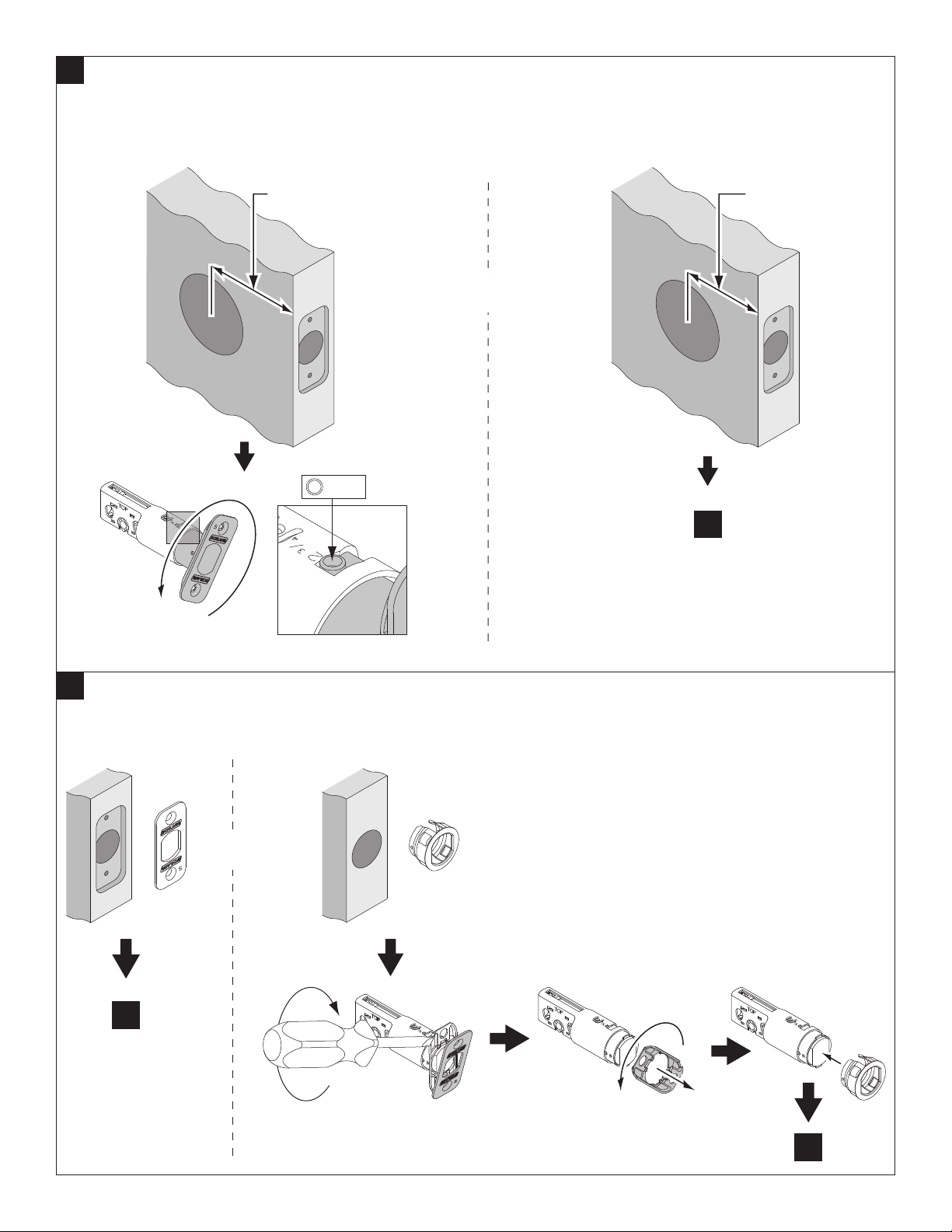
3
Check Backset
The backset is the distance from the edge of the door to the center of the hole through which the lock is installed.
This lock will fit either a 2C\,” backset or a 2C\v” backset. The bolt is preset to fit a 2C\,” backset. If your backset is not
2C\,”, you need to adjust your bolt by rotating it counterclockwise.
2³⁄₄” (70 mm)
2 ³⁄₄
2³⁄₈” (60 mm)
OR
4
4
Choose Faceplate
Choose the faceplate that most matches your existing door preparation. To use the round faceplate, first remove the
rectangular faceplate and back plate. Then attach the round faceplate.
OR
5
5
Page 4

5
Install Bolt
The word “TOP” should be facing upward as shown below.
Top Top
OR
(2)
6
Install the Keypad
Feed the cable over the top of the bolt assembly as shown below. Then slide the tailpiece through the correct hole
as shown below.
Tailpiece
Page 5

7
Check the Cam on the Baseplate
Locate the cam on the baseplate. This cam has a small arrow on it that should point to the arrow that is printed on
the casing above the cam, like picture “a” below. If the cam is oriented sideways, like the picture “b”, rotate the cam
until the arrows match.
a b
Cam
8
Install the Baseplate
Feed the cable through the hole as shown below. DO NOT connect the cable at this time. Then slide the
baseplate onto the tailpiece and press against the door. The baseplate should stay in place.
Tailpiece
Page 6

9
Secure the Baseplate to Door
Use the two screws shown to secure the baseplate to the door.
(2)
10
Connect the Cable
Snap the connectors together. Tuck them into the open space in the baseplate. Make sure no wires will be pinched
when the cover is installed.
Page 7

11
Install the Batteries
There are two sets of batteries. Install both the 9V and the AA batteries.
Remove screw here to
access AA battery tray.
b
c
12
Install the Cover
Place the cover against the door and secure using the two screws. You may need to rotate the thumbturn to the
proper position, shown below. Note that the top screw is longer and painted black.
Tuck wires into open space on baseplate. Be
careful not to pinch any wires between cover
!
and baseplate.
Thumbturn
Page 8

13
Prepare the Frame for the Strike
Place the reinforcement strike inside the strike hole and mark the 4 hole locations. Drill them as shown. If the strike
cut-out has not been prepared in the frame, see the “Strike cut-out specifications” box.
Drill 4 holes
Mark 4 holes
1"
(25 mm)
Strike cut-out specifications
1"
(25 mm)
14
Install the Strike
1¹⁄₂"
(38 mm)
¹⁄₈" (3 mm)
1¹⁄₈"
(29 mm)
2³⁄₄"
(70 mm)
Install for maximum security.
(2)(2)
Page 9

15
Test Locking Function
Make sure that the bolt extends as shown in the “correct” drawing below.
Test with door open to
!
avoid being locked out!
a. Press
b. Rotate turn towards
door edge until bolt extends
a
16
Test Unlocking Function
Test with door open to
!
avoid being locked out!
OR
Correct
Incorrect
If bolt does not extend, remove
lock from door. Follow steps5-10 to
reinstall lock.
Pay special attention to step 7. The
cam orientation is the most likely
source of a problem.
Programming Code XXXXXX
User Code A xxxx
User Code B xxxx
Press (four numbers)
17
This portion of the setup is complete.
S/N x-xxxxxxxx
Model BE369
on keypad
Green flash = unlock
Rotate turn away from door
edge and bolt will retract
Follow the directions on document to continue setup.
Document 2 is located at part2.schlage.com.
Page 10

This device complies with part 15 of the FCC rules. Operation is subject
to the following two conditions: (1) This device may not cause harmful
interference, and (2) this device must accept any interference received,
including interference that may cause undesired operation.
Changes or modifications to this equipment not expressly approved by
Schlage could void the user’s authority to operate the equipment.
FCC ID: P2GBE369 IC: 7654A-BE369
PATENT NOTICE
Schlage® products and those of its subsidiary companies and licensees
may be covered by both issued and pending U.S. and foreign patents,
copyrights and trademarks. Manufactured items are covered by one or
more of the following patents:
5070715
5152558
5308131
5395144
5593193
5598726
5640863
5683127
5715717
5765412
5769472
5809816
5816086
5820290
5881590
5918916
6286347
6297725
6523375
6533336
6540274
6581426
6802546
6905773
6926319
7143477
7159424
D372417
D372854
D406056
D406528
D426452
D428324
D450558
D457048
D457049
D458829
D467155
D472788
D487388
D520331
D520332
D537702
D541620
D543435
©2010 Schlage Lock Company
BE369 Online IS Rev. 03/10-b
 Loading...