

Page 1
© 2001 Ingersoll-Rand Co. May be copied for use with specification submittal.
2
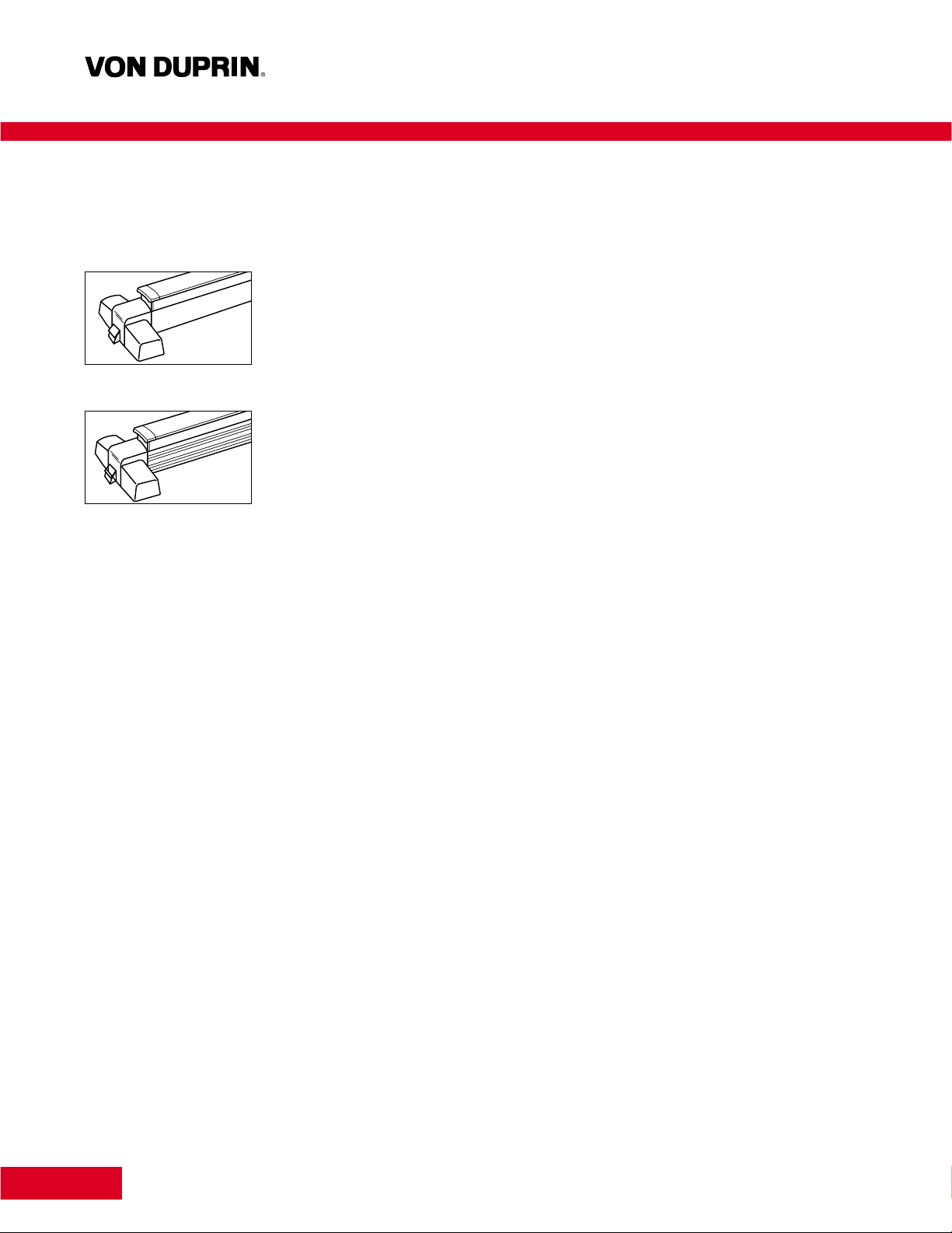
Chexit™Controlled Exit Device
Two styles — mechanically
and dimensionally identical,
for a wider selection of
appearance options.
CX98 Series features a
smooth mechanism care.
2
Introduction
Proper selection and application, in addition to safety, are major concerns to all responsible manufacturers.
Chexit Controlled Exit Device is a critical part of an access system, and will provide safe and reliable service
when properly applied and maintained. It is the policy of Von Duprin, Inc., to design and manufacture to a
high standard of quality and reliability in accordance with accepted U.S. domestic and international standards.
UL listed “Controlled Exit Panic Device,” for use on Panic Exit or Fire Exit hardware applications and
tested in accordance to ANSI A156.3, 2001, Grade I. Chexit meets all requirements for NFPA101, Special
Locking Arrangement.
It is intended that the information included in this publication, when properly used, will provide clear and
reliable guidelines to the proper general selection and application. However, the scope of the information
is necessarily limited.
Unusual operating conditions and environments, and other external influence can affect the proper application
of the products represented. Modifications of these products will also affect UL listings. It is recommended
whenever an unusual application condition exists, or when any modification of a product is considered, that
our engineers review the application.
Von Duprin, Inc. application engineering services are available to help ensure proper selection or to review any
areas where users of Von Duprin products may have questions.
Index
Introduction . . . . . . . . . . . . . . . . . . . . . . . . . . . . . 2
Chexit
™
Features . . . . . . . . . . . . . . . . . . . . . . . . . . 3
Exit Hardware
Rim Device. . . . . . . . . . . . . . . . . . . . . . . . . . . . . . 4
Mortise Lock Device. . . . . . . . . . . . . . . . . . . . . . . 5
Concealed Vertical Rod Device . . . . . . . . . . . . . . . 6
Wood Door Concealed Vertical Rod Device . . . . . . 7
Trims. . . . . . . . . . . . . . . . . . . . . . . . . . . . . . . . . 8-9
Strikes . . . . . . . . . . . . . . . . . . . . . . . . . . . . . 10-11
Strike Application/Minimum Stile . . . . . . . . . . . . 10
Accessories
Cylinders . . . . . . . . . . . . . . . . . . . . . . . . . . . . . . 13
Dummy Push Bar. . . . . . . . . . . . . . . . . . . . . . . . 13
Optional levers . . . . . . . . . . . . . . . . . . . . . . . . . . . 9
Cover Plate Kits . . . . . . . . . . . . . . . . . . . . . . . . . 13
Glass Bead Kit . . . . . . . . . . . . . . . . . . . . . . . . . . 13
CD Cylinder Dogging . . . . . . . . . . . . . . . . . . . . . 12
Electric Mortise Lock . . . . . . . . . . . . . . . . . . . . . 12
Electrical Power Transfer. . . . . . . . . . . . . . . . . . . 12
Mini Power Boosters . . . . . . . . . . . . . . . . . . . . . 12
Applications and Wiring. . . . . . . . . . . . . . . . 14-15
Additional Information
Electrical Specifications . . . . . . . . . . . . . . . . . . . 16
Finishes . . . . . . . . . . . . . . . . . . . . . . . . . . . . . . . 16
Fire Label Ratings/Applications. . . . . . . . . . . . . . 16
Handing of Doors . . . . . . . . . . . . . . . . . . . . . . . . 16
How-To-Order. . . . . . . . . . . . . . . . . . . . . . . . . . `17
Nomenclature. . . . . . . . . . . . . . . . . . . . . . . . . . . 18
Typical Specification. . . . . . . . . . . . . . . . . . . . . . 17
CX99 Series features a
grooved mechanism care.
Page 2
Chexit™Controlled Exit Device
3
Request to Exit Switch is built into the device to detect when someone attempts to exit. Applying less than
15 pounds to the push pad when the device is armed will cause this switch to start an irreversible alarm cycle.
Nuisance Alarm — When a Chexit is located in a public area, it can be desirable to limit false alarms. If the
Nuisance Audible and Nuisance Delay options are set to off, the device will go into alarm as soon as the push
pad is touched (when armed). Turning the Nuisance Delay on will require the push pad to be pressed for
2 seconds before the Chexit goes into alarm. If the Nuisance Audible and Nuisance Delay are both on, the
alarm will sound as soon as the push pad is pressed, but the alarm sequence will stop unless the push pad
is held for 2 seconds or more.
Remote Alarm — A set of relay contacts (rated 1 ampere, 24 VDC) are provided to give external alarm
indication. These contacts close when the device is in an irreversible alarm condition (If Nuisance Audible is
enabled, they will not close until the push pad has been held for more than 2 seconds). These contacts can
be used to drive a horn, lamp, or other indicative device.
Key Switch — The Key Switch provides the means to arm, disarm, or reset the Chexit. The key can be
removed in either the Arm or Disarm position. In cases where the key switch is not used for controlling the
device, a blank cylinder can be used.
Indicator Lamp — The status of the Chexit can be determined by the Indicator Lamp. A masked bezel design
provides wide angle viewing in any lighting condition. When the lamp is off, this indicates the device is disarmed
and is functioning as a normal exit device (no delay). A continuously on lamp indicates the device has just been
armed and as soon as the selectable rearm timer expires, the device will arm. A slow flashing lamp indicates
the device is armed. A fast flashing indicator lamp indicates the device is in alarm.
Internal Horn — Whenever the device is in alarm or the push pad is pressed the internal horn will sound. The
volume level of this horn exceeds 85 db at 6 feet. The user can select whether or not this horn sounds during a
fire alarm condition.
Door Position Input — An external door position switch can be connected to the Chexit. Doing this gives
added security to the opening and is recommended. If a door position switch is used, it will cause the alarm
to sound if the door is not closed when the device is armed; it will sound the alarm if the door is forced open
while the device is armed; it will provide anti-pass-back by cutting short the rearm time.
External Inhibit Input — This optional input is provided to allow remote override of the Chexit in the armed
condition. It also allows remote reset of the Chexit in an alarmed condition. Typical device connections include
card readers, wall-mounted key switches, or a remote security console. This input is controlled with a Normally
closed switch (open = disarmed).
Fire Alarm Input — This input disables the Chexit immediately upon a fire alarm. The building’s fire alarm
system should provide normally closed contacts which open on alarm.
Internal Auxiliary Lock — The Auxiliary Lock is engaged when the Chexit is armed. The locking mechanism is
specifically designed to hold securely even when the exit device is struck with forceful blows. The mechanism
will also release upon command irregardless of the force applied to the push pad. An override spring prevents
damage to internal components when more than 75 pounds of force are exerted on the push pad.
User Definable Rearm Time —
The Rearm Time is the amount of
time after the device is activated
(via key switch or external inhibit)
before it arms. It is designed to
give someone time to pass
through the door before arming
occurs. Timing can be changed
by the user for any time between
2 and 28 seconds in two
second increments.
There is also an infinite rearm
setting that requires the use of
an external door position switch.
In this setting the door remains
in the rearm mode until the door
is closed. This can be useful on
jet way doors in an airport.
Factory Definable Delay Time
— Most jurisdictions allow 15
seconds of delay before allowing
egress. In those cases where
15 seconds is not appropriate,
Von Duprin can set the Chexit
for any delay time between 0
and 60 seconds on 2 second
increments. For delays greater
than 15 seconds a letter from
the local authority is required.
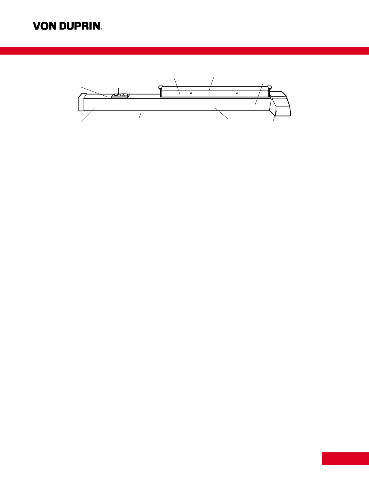
Features
Indicator Lamp Key Switch Nuisance Alarm Request to
Exit Switch
Internal Horn
External Inhibit Input
Patent #5,011,199
Fire Alarm Input Door Position Input Remote Alarm Internal Auxiliary
Lock
FEATURES
Indicator Lamp
External Inhibit Input
Key Switch
Nuisance Alarm
Request to
Exit Switch
Internal Horn
Fire Alarm Input
Internal Auxiliary
Lock
Door Position Input
Remote Alarm
Patent #5,011,199
Page 3
4
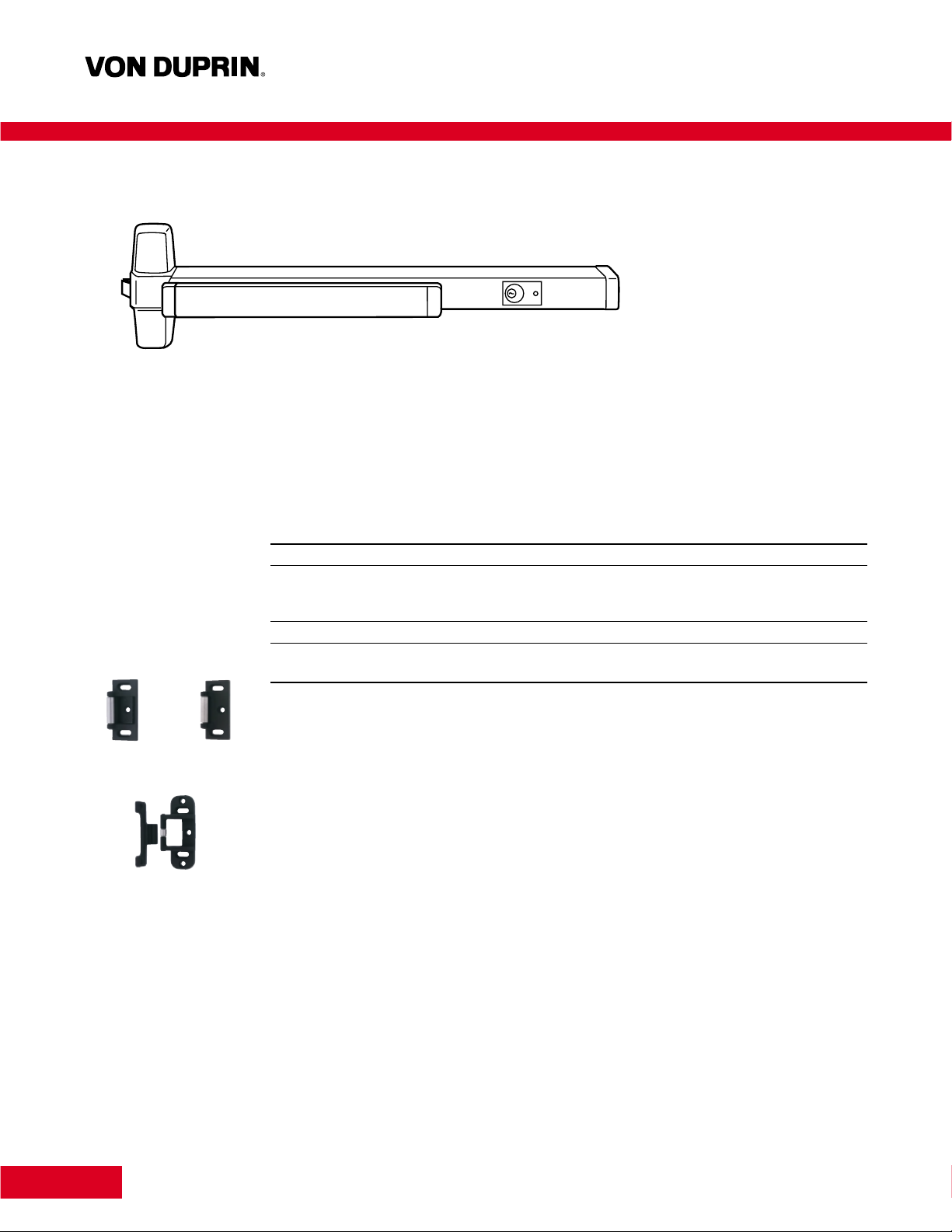
Chexit™Rim Device
CX98 and CX99 rim devices for all types of single doors and double doors with mullion, UL listed for accident
hazard installations. Covers stock hollow metal doors with 86 or 161 cutouts.
CX98-F and CX99-F fire exit rim devices for all types of 4' x 8' (1219mm x 2438mm) single doors or 8' x 8'
(2438mm x 2438mm) double doors with 9954 mullion, UL listed for A, B, C, D or E fire-labeled installations.
Features
• Nonhanded • Latch bolt dead locking
• Field sizeable • Eight popular finishes
• 3/4" (19mm)throw, latch bolt
Dimensions
Touchbar height to finished floor 39-13/16" (1011mm) at center
Touchbar projection —
neutral 3-13/16" (97mm)
depressed 3-1/16" (78mm)
Center case 8" x 2-1/4" x 2-3/4" (203mm x 57mm x 70mm)
Device length — Short 3' (914mm) 2'10" to 3' (864mm to 914mm) door size
Long 4"1(1219mm) 3'4" to 4' (1016mm to 1219mm) door size
Strikes and Fasteners
Device is furnished with standard 299 or 299F strikes in dull black finish, 499F is required on double fire doors.
For optional strikes, finishes, applications, dimensions and minimum door stile information refer to page 10.
A combination of fasteners are included for surface mounting and through bolting to trim on 1-3/4" (44mm)
and 2-1/4" (57mm) thick doors.
Device Option
Cylinder dogging, page 13
For How-To-Order Information on all devices, see page 17.
For electrical specifications, see page 16.
For power supply and power transfer information, see page 12.
Standard 1-1/4" (32mm) mortise cylinder
must be ordered separately.
299 299F
499F
Page 4
5
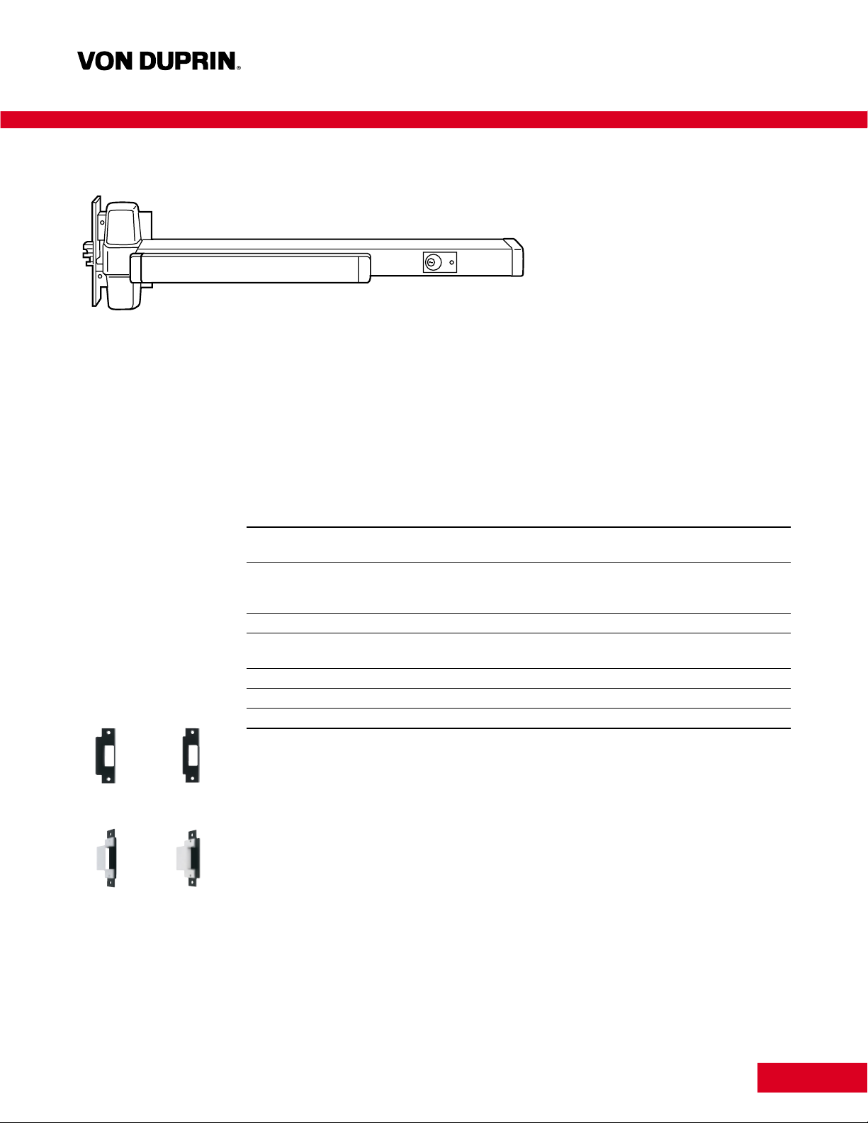
Chexit™Mortise Lock Device
575 575-2
576A 576B
CX9875 and CX9975 mortise lock devices for all types of single doors or double doors, UL listed for
accident hazard installations. Fits stock hollow metal doors with 86 cutout, and door stiles as narrow as
4-3/4" (121mm).
CX9875-F and CX9975-F fire exit mortise lock devices for all types of 4' x 10' (1219mm x 3048mm) single
doors or 8' x 8' (2438mm x 2438mm) double door installations, UL listed for A, B, C, D or E fire-labeled
installations. Fits door stiles as narrow as 4-3/4" (121mm).
Features
• Nonhanded • 3/4" (19mm)throw, anti-friction latch bolt
• Full reversible mortise lock • Latch bolt deadlocking
• Field sizeable • Eight popular finishes
Dimensions
Touchbar height to finished floor 39-5/8" (1006mm) at center
Latch bolt height to finished floor 40-3/32" (1018mm) at center
Touchbar projection —
neutral 3-13/16" (97mm)
depressed 3-1/16" (78mm)
Center case 8" x 2-1/4" x 2-3/4" (203mm x 57mm x 70mm)
Device length — Short 3' (914mm) 2'10" to 3' (864mm to 914mm) door size
Long 4"1(1219mm) 3'4" to 4' (1016mm to 1219mm) door size
Lock case 4-5/8" x 5-3/4" x 1-1/16" (118mm x 146mm x 27mm)
Faceplate 1-1/4" x 8" x 7/32" (32mm x 203mm x 6mm)
Cylinder backset 2-3/4" (70mm)
Strikes and Fasteners
Device is furnished with standard 575 strike in dull black finish. For optional strikes, finishes and dimensions
refer to page 10.
575 Strike — for use on 1-3/4" (44mm) or 2-1/4" (57mm) single doors and 2-1/4" (57mm) double doors
with coordinator.
575-2 Strike — for use on 1-3/4" (44mm) double doors with coordinator.
576A Strike — open back strike for 1-3/4" (44mm) double doors without coordinator.
576B Strike — open back strike for 2-1/4" (57mm) double doors without coordinator.
A combination of fasteners are included for surface mounting and through bolting to trim on 1-3/4" (44mm)
and 2-1/4" (57mm) thick doors.
Device Option
Cylinder dogging, page 13
For How-To-Order Information on all devices, see page 17.
For electrical specifications, see page 16.
For power supply and power transfer information, see page 12.
Standard 1-1/4" (32mm) mortise cylinder
must be ordered separately.
When using Chexit mortise lock,
the outside trim will operate the
door without affecting the device
in an armed conditioned, if a
door position switch is not used.
The 7500 Mortise lock is
equipped with a 3/4" (19mm)
anti-friction latch bolt which is
field reversible without removing
the lock from the door. It has a
nonhanded auxiliary bolt for
deadlocking, and a faceplate
which has an adjustable bevel.
Field selection of functions are
furnished standard. TP, K or L
function may be field selected
by adjusting a set screw. Electric
locking and unlocking, and
signal switch options are
available, refer to page 11.
Page 5
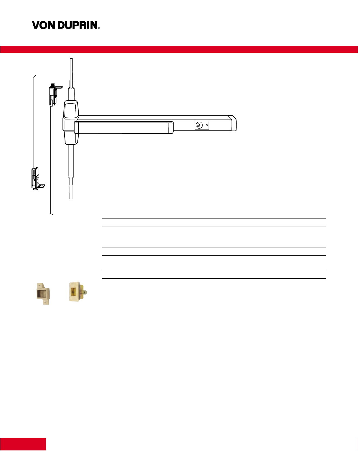
Chexit™Concealed Vertical Rod Device
6
CX9847 and CX9947 concealed vertical rod devices for use on single or double metal doors, UL listed for
accident hazard installations. Covers stock hollow metal doors with 86 or 161 cutouts.
CX9847-F and CX9947-F fire exit concealed vertical rod devices for use on 8' x 8' (2438mm x 2438mm)
double metal doors, UL listed for A, B, C, D or E fire-labeled installations.
Features
• Nonhanded • 5/8" (16mm)throw, latch bolt
• Field sizeable • Latch bolt deadlocking
• Adjustable top rod • Eight popular finishes
Dimensions
Touchbar height to finished floor 39-5/8" (1006mm) at center
Touchbar projection —
neutral 3-13/16" (97mm)
depressed 3-1/16" (78mm)
Center case 8" x 2-1/4" x 2-3/4" (203mm x 57mm x 70mm)
Device length — Short 3' (914mm) 2'10" to 3' (864mm to 914mm) door size
Long 4"1(1219mm) 3'4" to 4' (1016mm to 1219mm) door size
Vertical rods — round Two piece adjustable top rod
Strikes and Fasteners
Device is furnished with standard 338 and 385A strikes. For optional strikes, finishes, applications, dimensions
and minimum door stile information refer to page 10.
A combination of fasteners are included for surface mounting and through bolting to trim on 1-3/4" (44mm)
and 2-1/4" (57mm) thick doors.
Device Option
Cylinder dogging, page 13
For How-To-Order Information on all devices, see page 17.
For electrical specifications, see page 16.
For power supply and power transfer information, see page 12.
Standard 1-1/4" (32mm) mortise cylinder
must be ordered separately.
Surface mounted vertical rod
devices are available, but not
recommended unless used with
rod and latch guards and monitor
strike, consult factory.
338 385A
Page 6
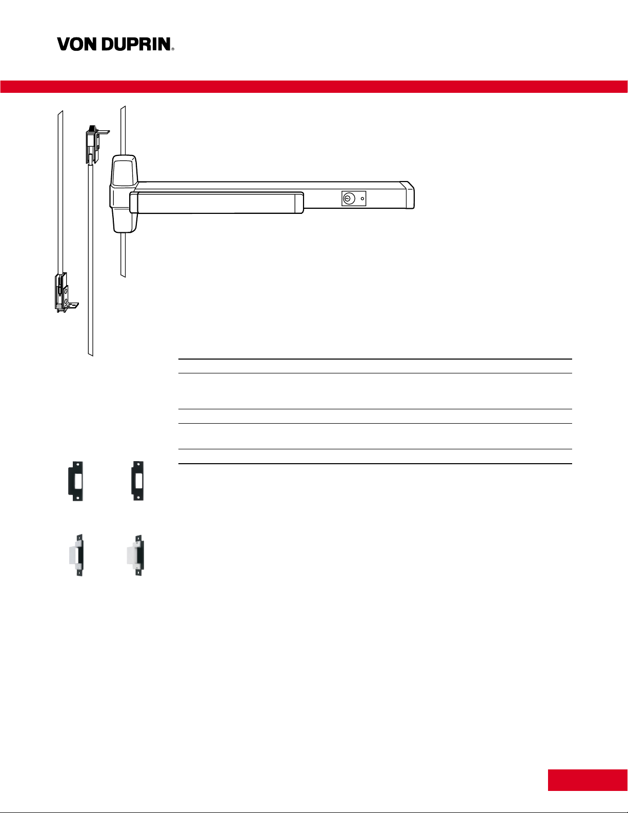
Chexit™Wood Door Concealed Vertical Rod Device
7
CX9847WDC and CX9947WDC concealed vertical rod devices for use on single or double wood doors, UL
listed for accident hazard installations.
CX9847WDC-F and CX9947WDC-F fire exit concealed vertical rod devices for use on 8' x 9'3" (2438mm x
2819mm) double wood doors, UL listed for B, C, D or E fire-labeled installations. For use on approved doors only.
Features
• Nonhanded • 5/8" (16mm)throw, latch bolt
• Field sizeable • Latch bolt deadlocking
• Adjustable top rod • Eight popular finishes
Dimensions
Touchbar height to finished floor 39-5/8" (1006mm) at center
Touchbar projection —
neutral 3-13/16" (97mm)
depressed 3-1/16" (78mm)
Center case 8" x 2-1/4" x 2-3/4" (203mm x 57mm x 70mm)
Device length — Short 3' (914mm) 2'10" to 3' (864mm to 914mm) door size
Long 4"1(1219mm) 3'4" to 4' (1016mm to 1219mm) door size
Vertical rods — round Two piece adjustable top rod
Strikes and Fasteners
Device is furnished with standard 338 and 385A strikes. For optional strikes, finishes, applications, dimensions
and minimum door stile information refer to page 10.
A combination of fasteners are included for surface mounting and through bolting to trim on 1-3/4" (44mm)
and 2-1/4" (57mm) thick doors.
Device Option
Cylinder dogging, page 13
Scalp Plate
Device is furnished standard with an 8" (203mm) long scalp plate for easy access to rods.
For How-To-Order Information on all devices, see page 17.
For electrical specifications, see page 16.
For power supply and power transfer information, see page 12.
Standard 1-1/4" (32mm) mortise cylinder
must be ordered separately.
575 575-2
576A 576B
Page 7

8
Trim Selection
Trim operation — rim and vertical rod application, trim will notfunction when Chexit is armed. Mortise application, trim will function when
Chexit is armed.
01 02 03 03 05 08 08 11/12
Function Pull When Key Retracts Key Retracts Key Locks Key Locks Key Locks Key Locks
Exit Only Dogged Latch Bolt Latch Bolt Thumbpiece Knob Lever Thumbturn
990DT 990NL NL-OP 990TP 991K 992L 376T
376T-WDC
Trim Number
and Dimensions
Device/Trim Center Line
To Finished Floor
Projection —2" (51mm) 2" (51mm) —2" (51mm) 3-3/4" (95mm) 2-3/4" (70mm) 1-3/4" (44mm)
A CX98EO ACX98DT CX98NL A CX98NL-OP A CX98TP A CX98K A CX98L
—
Panic A CX99EO ACX99DT CX99NL A CX99NL-OP A CX99TP A CX99K A CX99L
A CX98EO-F A
—
CX98NL-F A CX98NL-OP-F ACX98TP-F ACX98K-F A CX98L-F
—
Fire▲ ACX99EO-F CX99NL-F A CX99NL-OP-F ACX99TP-F ACX99K-F A CX99L-F
A 39-13/16" —A 39-13/16" B 33-7/8" A 39-13/16" B 33-7/8" A 39-13/16" B 40-1/16" A 39-13/16" B 33-7/8" A 39-13/16" B 37-3/16" A 39-13/16" B37-3/16"
— —
Ctr. Line 1011mm 1011mm 860mm 1011mm 860mm 1011mm 1018mm 1011mm 860mm 1011mm 945mm 1011mm 945mm A10
A CX9875EO A CX9875DT CX9875NL A CX9875NL-OP A CX9875TP A CX9875K A CX9875L
—
Panic A CX9975EO A CX9975DT CX9975NL A CX9975NL-OP A CX9975TP A CX9975K A CX9975L
A CX9875EO-F
A —
CX9875NL-F A CX9875NL-OP-F A CX9875TP-F A CX9875K-F A CX9875L-F
—
Fire ACX9975EO-F A A CX9975NL-F A CX9975NL-OP-F A CX9975TP-F A CX9975K-F A CX9975L-F
A 39-5/8" —A 39-5/8" B 33-11/16" A 39-5/8" B 33-11/16" A 39-5/8" B 39-7/8" A 39-5/8" B 33-11/16" A 39-5/8" B 37" A 39-5/8" B 37"
Ctr. Line 1006mm 1006mm 856mm 1006mm 856mm 1006mm 1012mm 1006mm 856mm 1006mm 940mm 1006mm 940mm
A CX9847EO A CX9847DT CX9847NL A CX9847NL-OP A CX9847TP A CX9847K A CX9847L CX9847TL
Panic A CX9947EO A CX9947DT CX9947NL A CX9947NL-OP A CX9947TP A CX9947K A CX9947L CX9947TL
A CX9847EO-F
A —
CX9847NL-F A CX9847NL-OP-F A CX9847TP-F A CX9847K-F A CX9847L-F CX9847TL-F
Fire ACX9947EO-F CX9479NL-F A CX9947NL-OP-F A CX9947TP-F A CX9947K-F A CX9947L-F CX9847TL-F
A 39-5/8" —A 39-5/8" B 33-11/16" A 39-5/8" B 33-11/16" A 39-5/8" B 33-11/16" A 39-5/8" B 39-7/8" A 39-5/8" B 33-11/16" A39-5/8" B37" A 39-5/8" B 37"
Ctr. Line 1006mm 1006mm 856mm 1006mm 856mm 1006mm 1012mm 1006mm 856mm 1006mm 940mm 1006mm 940mm 1006mm 940mm
A CX9847WDC-EO A CX9847WDC-DT CX9847WDC-NL A CX9847WDC-NL-OP ACX9847WDC-TP CX9847WDC-K ACX9847WDC-NL CX9847WDC-TL
Panic A CX9947WDC-EO A CX9947WDC-DT CX9947WDC-NL A CX9947WDC-NL-OP A CX9947WDC-TP CX9947WDC-KK ACX9947WDC-NL CX9947WDC-TL
A CX9847WDC-EO-F
A —
CX9847WDC-NL-F A CX9847WDC-NL-OP-F ACX9847WDC-TP-F CX9847WDC-K-F A CX9847WDC-NL-F CX9847WDC-TL-F
Fire ACX9847WDC-EO-F CX9947WDC-NL-F A CX9947WDC-NL-OP-F ACX9947WDC-TP-F CX9947WDC-K-F A CX9947WDC-NL-F CX9947WDC-TL-F
A 39-5/8" —A 39-5/8" B 33-11/16" A 39-5/8" B 33-11/16" A 39-5/8" B 39-7/8" A 39-5/8" B 39-7/8" A 39-5/8" B 33-11/16" A 39-5/8" B 37" A 39-5/8" B 59-1/2"
Ctr. Line 1006mm 1006mm 856mm 1006mm 856mm 1006mm 1012mm 1006mm 1012mm 1006mm 856mm 1006mm 940mm 1006mm 1359mm
A
A
6 A 2 A 2 A 6 A2 A 2 A2 A 2
Device Type
Rim — — Rim Rim Rim Rim Rim —
Mortise — — Mortise Mortise Mortise Mortise Mortise Mortise
Vert. Rod — — Rim Rim Rim Rim Rim Mortise
▲ Sex bolts application — when using 499-F strike, two additional 425 sex bolts are required. Wood door applications require two additional 825 sex bolts.
●Sex bolts are required on wood or composite fire door applications.
Rim
Mortise
Lock
Concealed
Vertical
Lock
Concealed
Vertical
Rod
Wood Door
Sex bolt application
quantity requirements
●
Cylinder
Type
Required
14 3/16"
(360mm)
3"
(76mm)
14 3/16"
(360mm)
3"
(76mm)
1 1/4"
(32mm)
Rim
Cylinder
Only
14 3/16"
(360mm)
3"
(76mm)
2 5/8"
(67mm)
10 5/8"
(270mm)
10 5/8"
(270mm)
2 5/8"
(67mm)
1 3/4"
(44mm)
7 1/2"
(191mm)
A
B
A
B
A
A
B
B
A
A
B
A
B
A
B
Page 8
9
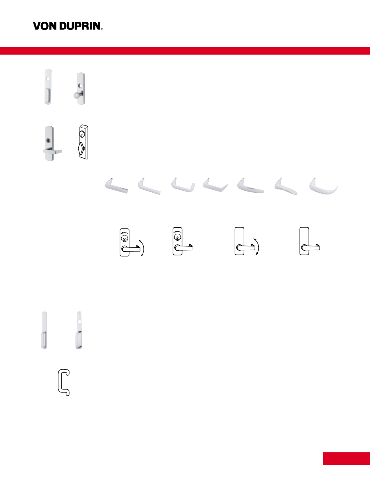
Trim Selection
Standard Trim
Series 990
Heavy 10 gage (2.4mm) brass, bronze or stainless steel. DT, NL or TP functions
Series 991
Forged brass 3/4" (19mm) thick. Operational options — K, DT, NL or BE
Series 992
Forged brass 3/4" (19mm) thick. Operational options — L, DT, NL or BE
Series 370
Forged brass 7/8" (22mm) thick escutcheon.
Lever Design Options
To order:Use suffix lever number, example 9927L x 01.
Operation Options — Lever and Knob
Optional Trim
Series 696
Narrow design 3/16" (5mm) thick brass, bronze or stainless steel. DT, NL or TP functions. Flat pull grip.
Series 697
Narrow design 3/16" (5mm) thick brass, bronze or stainless steel. DT, NL or TP functions. Round wire pull grip.
Series 390
Offset solid brass, bronze or stainless steel 3/4" (19mm) wire pulls, 7" (178mm) in length. Through bolts to Chexit.
#01 #02 #03 #06 (Std.) #07 #12
#17
Standard operation, key
locks and unlocks lever.
Night latch, key
retracts latch bolt, lever
is rigid. Use NL suffix,
i.e., 992L-NL.
Blank escutcheon, lever
always active. Use BE
suffix, i.e., 992L-BE.
Dummy trim, lever rigid
for pull operation. Use
DT suffix, i.e., 992L-DT.
990NL 991K
992L 370T
696 697
390
Page 9
10
Strike Application Information
Strike Application/Minimum Stile Using Standard Trim
Standard Optional
Single door Double door Single door Double door
Strike Stile Strike w/Mullion* Stile Strike Stile Strike w/Mullion* Stile
1409 3-13/16" (97mm) 299 x 5654 4-7/16" (113mm)
CX98 299 4-1/2" (114mm) 299 x 4954 4-7/8" (124mm) 1410 3-13-16" (97mm) 1408 x 5754 3-13/16" (97mm)
CX99 1606 4-1/16" (103mm) 1606 x 1654 4-7/16" (113mm)
CX98-F/CX99-F 299F 4-1/2" (114mm) 499F x 9954 4-7/8" (124mm) —— — —
Strike Stile Strike Stile Strike
CX9875 575-2
CX9975 575 4-3/4" (121mm) — — — — 576A-576B 4-3/4" (121mm)
CX9875-F 575-2
CX9975-F 575 4-3/4" (121mm) — — — — 576A-576B 4-3/4" (121mm)
Strike Application Stile Strike Application Stile
CX9847 338 (Top) Single door 3-11/16" (94mm) 283 (Top) Single door 3-11/16" (94mm)
CX9947 385A (Bottom) Two Vertical 304L (Bottom) Two V ertical
CX9847WDC Rod Devices 3-11/16" (94mm) Rod Devices 3-11/16" (94mm)
CX9947WDC Vertical Rod Vertical Rod
w/Mortise w/Mortise
Lock Device 4-3/4" (121mm) Lock Device 4-3/4" (121mm)
CX9847-F 338 (Top) Two Vertical 4-1/4" (108mm) 304L (Bottom) Single door 4-1/4" (108mm)
CX9947-F 385A (Bottom) Rod Devices Rod Devices
CX9847WDC-F
CX9947WDC-F
*Mullion information — refer to General and Auxiliary section.
Device
Type
Page 10
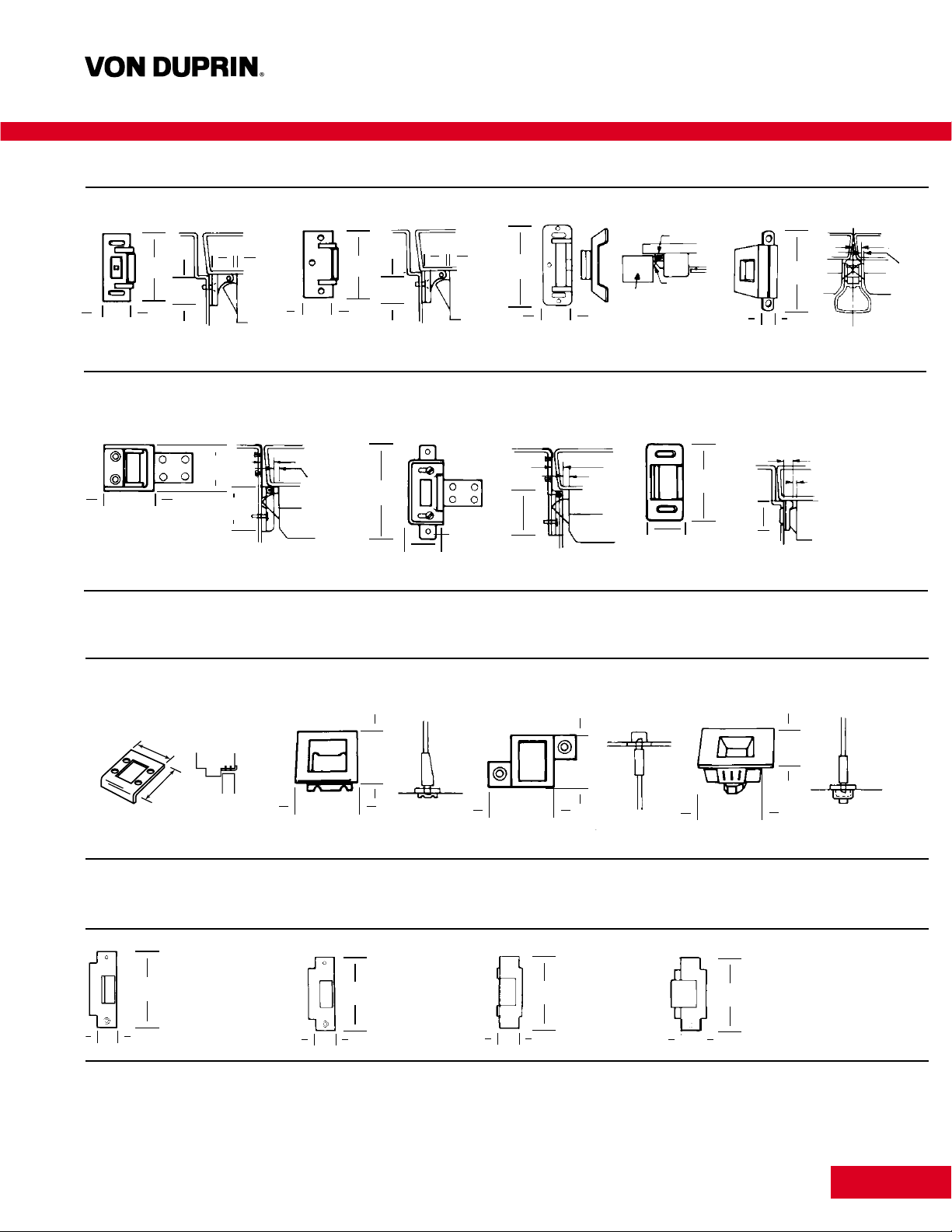
Strikes for Rim Devices
299 299F 499F 1408
Projection 13/16" (21mm) Projection 13/16" (21mm) Projection 13/16" (21mm) One per pair of doors
1409 — Blade Stop 1410 — Integral Stop 1606
Projection 1/2" (13mm) Projection 1/2" (13mm) Projection 3/8" (10mm
Strikes for Vertical Rod Devices
283 304L 338 385A
Projection 3/8" (10mm) Mortise 13/16" (21mm) Mortise 5/8" (16mm) Mortise 2-1/2" (64mm)
Strikes for Mortise Lock Devices
575 575-2 576A 576B
27/8
(73mm)
11/4
(32mm)
11/4
(32mm)
1
/4
(6mm)
13
/16
(21mm)
27/8
(73mm)
11/4
(32mm)
11/4
(32mm)
1
/4
(6mm)
13
/16
(21mm)
41/4
(108mm)
11/2
(32mm)
Mullion
Hook
Strike
3
7
/16
(87mm)
23/8
(60mm)
3
/16
(5mm)
1
/2
(13mm)
11
Strike Application Information
33/16
(81mm)
27/8
(73mm)
13/8
(35mm)
13/8
(35mm)
3
/8
(10mm)
3
/16
(5mm)
13/8
(35mm)
5
/8
(15mm)
29/16
(63mm)
3
/16
(5mm)
3
/16
(5mm)
1
/2
(13mm)
17/8
(48mm)
13/4
(44mm)
17/8
(48mm)
17/8
(48mm)
17/8
(48mm)
15/8
(41mm)
17/8
(48mm)
2
(51mm)
23/4
(70mm)
47/8
(124mm)
11/4
(32mm)
47/8
(124mm)
11/4
(32mm)
47/8
(124mm)
11/4
(32mm)
47/8
(124mm)
11/4
(32mm)
For use on 1-3/4" (44mm)
or 2-1/4" (57mm) Single
door and 2-1/4" (57mm)
double door with
coordinator.
For use on
1-3/4" (44mm)
thick double
door with
coordinator.
Open back strike
for 1-3/4" (44mm)
thick double doors
without coordinator.
Open back strike
for 2-1/4" (57mm)
thick double doors
without coordinator.
1 3/4"
(43mm)
2"
(51mm)
Page 11

Electric Mortise Lock
The electric mortise lock has all the versatility and advantages of the
standard mortise lock, plus being electrically controllable by a remote
switching device, and access control or automatic fire alarm system.
The E7500 controls the locking of the outside trim. When unlocked,
the door remains latched, preserving the fire rating of the door and
making it particularly useful where codes permit locking, but require
unlocking during a fire emergency.
Standard Features
• Field reversible
• 24 VDC continuous duty solenoid
• Silent operation
• Signalling functions
• Corrosion resistant
• Tamper resistant
• Key mechanically retracts latchbolt
Optional Features
• Fail secure (unlocked when energized, locked when de-energized or
during power failure). Furnished standard.
• Fail safe (unlocked when energized, unlocked when de-energized or
during power failure). Specify with suffix “FS”.
• 24 VAC (by adding SO option)
• 12 VDC or 12 VAC (with SO option)
Note: Some Fire codes will require “Fail Safe” (FS) operation for stairwell doors. Be sure to specify the correct operation for your application.
Electrical Power Transfer
The EPT-10 provides a means to transfer
power from the frame to the door stile in
Chexit applications. It is used in installations
with 4-1/2" x 4-1/2" (114mm x 114mm) butt
hinges or 3/4" (19mm) offset pivots. The
EPT-10 is reversible and allows a full (180°)
door swing. When the door is closed, the unit
is concealed for tamper resistance.
UL approved component for use with listed rim, mortise and vertical
rod fire devices.
Dimensions:
Housing 9" x 1-7/16" x 1-1/2"
(23mm x 37mm x 38mm)
Conductors Ten 24 AWGUL Approved
Rating 10 Amps. at 24 VDC
(Class 1 low voltage)
(20 Amp. maximum surge)
Power Supplies
PS873 are UL approved power
supplies and specifically designed to
handle Chexit controlled exit device.
The PS873 is a 24 VDC, 2 Amp, regulated power supplies, 120 VAC
input and can power up to four Chexits, but the rearm times must be
staggered so that no two devices rearm at the same time.
Refer to the Door Control and Security Products Catalog for complete
power supply information.
Specifications:
Housing Surface Mount, No Lock
10" H x 12-1/2" W x 5" D
(254mm x 323mm x 127mm)
Output 2.0 Amperes Continuous @ 24 VDC
16.0 Amperes Surge For 300 milliseconds
Inputs (Primary) 120 VAC — 102-132 VAC @ 1 Amp.
240 VAC — 204-264 VAC@ 1/2 Amp.
12
Accessories and Options
Page 12
13
Accessories and Options
CD Cylinder Dogging
Cylinder dogging option is available to
allow push/pull operation of Chexit, when
disarmed and used in a heavy traffic area.
For typical electronic applications see pages 14-15.
Glass Bead Kit
Glass bead conversion kits are available for use on
doors with raised glass beads. Kit consists of 1/8"
(3mm) shim sets.
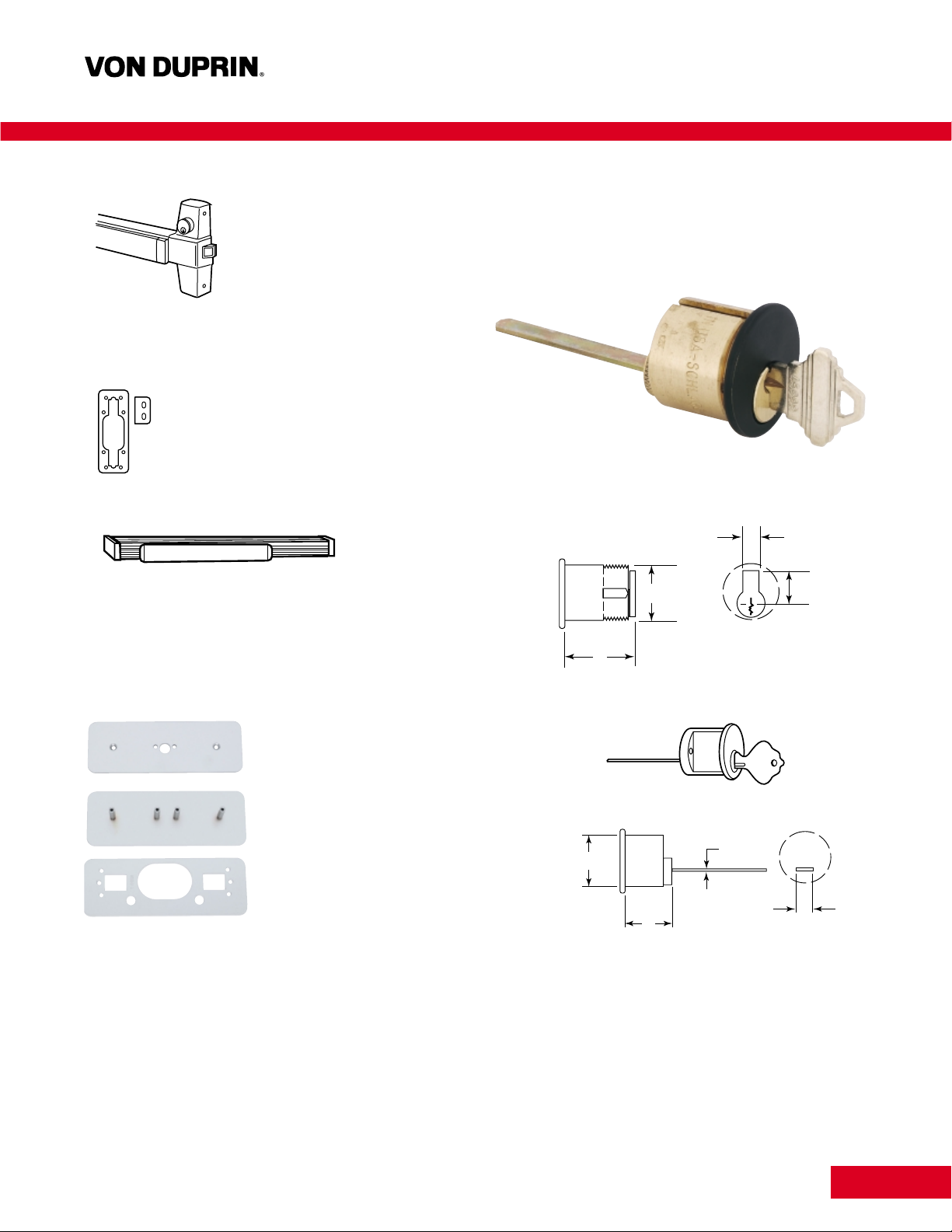
Dummy Push Bar
The 330 grooved and 350 smooth dummy push bars are designed
as a companion unit for all 98 or 99 devices. The touch bar is rigid
or non-functioning. A push/pull operation can be accomplished by
using 990DT or other pull trim.
Cover Plate Kit — 997 Kit
For rim device, kit contains
inside and outside plates for hinge
stile, an inside plate for the lock
stile, and fasteners. Designed
to cover most cutouts,
3-1/4" (83mm) x 9" (229mm).
Cylinders
Cylinders are not furnished with device or trim and must be specified
when ordering. Rim, surface vertical rod, and concealed vertical rod
exit devices use rim type cylinders. Mortise lock exit devices and series
370 controls use mortise type cylinders.
A
B
1 5/32''
(29mm)
1 1/4''
(32mm)
5
/16 – 3/8''
(8 – 9mm)
11
/16 – 3/4''
(17 – 19mm)
A
B
1 5/32''
(29mm)
1 1/4''
(32mm)
5
/64'' max.
(2mm)
1
/4'' max.
(6mm)
Page 13

14
Applications and Wiring
Legend: + 24 = 24 Volt DC; GND = Ground; SC = Signal Common; FA = Fire Alarm (input); DPS = Door Position Switch; El = External Inhibit; (input) CM+ = Communication Line;
CM- = Communication Line; NO = Normally Open External Alarm; C = Common External Alarm.
Basic Chexit single door application configuration consists of the Chexit
device, power transfer and PS873 power supply. Using this setup, the
Chexit will delay egress when armed and act as a normal exit device
when turned off.
120 VAC
3 x 14 ga.
To Fire Alarm
2 x 18 ga.
Junction
Box
EPT-10
PS871/873
Power Supply
PS871/873
Power Supply
Cable
2 x 12 ga.
2 x 18 ga.
2 x 12 ga.
Gnd
Gnd
+24
+24
SC
FA
DPS
EI
CM+
CM–
NO
C
Chexit
Cable
Red
Black
White
Yellow
Orange
Green
Gray
Violet
Blue
Brown
Fire Alarm
120 VAC
3 x 14 ga.
To Fire Alarm
2 x 18 ga.
Junction
Box
EPT-10
Horn
PS871/873
Power Supply
PS871/873
Power Supply
Cable
2 x 12 ga.
6 x 18 ga.
2 x 18 ga.
(input)
Gnd
Gnd
+24
+24
SC
FA
DPS
EI
CM+
CM–
NO
C
Chexit
Cable
Red
Black
White
Yellow
Orange
Green
Gray
Violet
Blue
Brown
Fire Alarm
Card Reader
Door Position Switch
Horn
2 x 12 ga.
2 x 18 ga.
2 x 18 ga.
Card
Reader
(Inside or
Outside)
+ –
Chexit Single Door with Options — The Chexit is used as an access
control device. The card reader allows access. Also shown in this
application is an external horn and door position switch. The auxiliary
horn is used for increased volume in remote locations. Using a door
position switch gives added security to the opening in case the door
is not reclosed.
With the Chexit disarmed, the opening functions as a normal exit device.
If card readers are required on both sides of the door, the normally
closed contacts of the readers should be wired in series.
PS873
PS873
PS873
PS873
Page 14

15
Applications and Wiring
Basic Chexit Double Door application. When one Chexit is set into
alarm, the other will also go into alarm. In an emergency situation both
doors will disarm simultaneously.
Double Door Chexit with Options shows the proper wiring for double
door. The card reader will unlock both doors upon authorized access.
For proper operation the rearm times are set two seconds apart.
PS873
PS873
120 VAC
3 x 14 ga.
2 x 12 ga.
PS871/873
To Fire Alarm
2 x 18 ga.
Junction
Box
2 x 12 ga.
3 x 18 ga.
EPT-10 EPT-10
Cable Cable
Power Supply
2 x 12 ga.
3 x 18 ga.
Fire Alarm
+24
Gnd
PS871/873
Power Supply
Chexit 1
+24
Gnd
SC
FA
DPS
EI
CM+
CM–
NO
C
Chexit 2
+24
Gnd
SC
FA
DPS
EI
CM+
CM–
NO
C
Red
Black
White
Yellow
Orange
Green
Gray
Violet
Blue
Brown
Red
Black
White
Yellow
Orange
Green
Gray
Violet
Blue
Brown
120 VAC
3 x 14 ga.
2 x 12 ga.
To Fire Alarm
2 x 12 ga.
8 x 18 ga.
2 x 18 ga.
2 x 18
ga.
Junction
Box
Magnetic
Switch
2 x 18 ga.
Magnetic
Switch
EPT-10 EPT-10
Cable Cable
PS871/873
Power
Supply
2 x 18 ga.
2 x 12 ga.
8 x 18 ga.
2 x 18 ga.
(input)
Card
Reader
(Inside or
Outside)
Horn
+24
Gnd
Horn
Fire Alarm
Card Reader
Door
Position
Door
Position
Chexit 1
+24
Gnd
SC
FA
DPS
EI
CM+
CM–
NO
C
Chexit 2
+24
Gnd
SC
FA
DPS
EI
CM+
CM–
NO
C
Red
Black
White
Yellow
Orange
Green
Gray
Violet
Blue
Brown
Red
Black
White
Yellow
Orange
Green
Gray
Violet
Blue
Brown
Page 15

16
Additional Information
Finishes
Color US Number BHMA Number A B C D E
Brass, Polished US3 605 Brass Plated Brass Buffed Anodized Brass
Brass, Satin US4 606 Brass Plated Brass Anodized Brass
Bronze, Satin US10 612 Bronze Anodized Bronze Anodized Bronze
Chrome, Polished US26 625 Stainless Steel Plated Stainless Steel Buffed Anodized Stainless Steel
Chrome, Satin US26D 626 Stainless Steel Plated Stainless Steel Anodized Plated
Aluminum, Anodized US28 628 Painted Painted Stainless Steel Anodized Painted
Stainless Steel, Satin
▲
US32D 630 Stainless Steel Stainless Steel Stainless Steel Anodized Stainless Steel
Duranodic Dark Bronze 313AN — Painted Painted Walnut Grain Vinyl Anodized Painted
Push Pad Options — Black Vinyl, Brass, Bronze or Stainless Steel.
▲Finish available on Series 98, only.
Fire Label Rating/Applications
Single Door Double Door
Without Mullion
Same Direction Without Mullion
With 9954 Mullion Vert./Vert.-Vert./Mrt. Double Express
Device 4' x 8' 4' x 10' 4' x 8' 8' x 8' 8' x 8'
UL Listing (1219mm x 2438mm) (1219mm x 3050mm) (1219mm x 2438mm) (2438mm x 2438mm) (2438mm x 2438mm)
CX98-F/CX99-F A Label X — X — —
CX9875-F/CX9975-F A Label X X — X —
CX9847-F/CX9947-F A Label▲—— — X X
CX9847WDC-F/CX9947WDC-F B Label■—— — X —
▲Special latches available for up to 10'0" (3048mm).
■ Approved for up to 9'3" (2819mm)
Electrical Specifications
Voltage — 24 VDC
Current — .4 Ampere with 300 millisecond 16 Ampere
in-rush on arming
External Alarm Contact Rating — 24 VDC, 1 Ampere
Fire Alarm Input, External Inhibit Input, Door Position Input —
setup for Normally Closed contacts.
Handing of Doors
Left Hand
Orientation
Right Hand
Orientation
LHR
(Left hand reverse)
RHR
(Right hand reverse)
Outside
A — Center Case
B — Push Pad
End Cap
B — Push Pad
End Cap
C — Push Pad
D — Mechanism Housing E — Mechanism End Cap
Page 16

1717
Additional Information
Typical Specification
Basic System Design
Each Chexit controlled exit device is an emergency exit system consisting of a door or pair of doors equipped with Von Duprin CX99
exit device(s). The system has three modes of operation command:
• Emergency Save Exit Mode
• Secure Mode with Alarm and Conditional Release
• Authorized Exit Mode
Emergency Safe Exit Mode
Whenever the safety detector (smoke, fire, water flow, etc.) signals
that an emergency condition is present to the Chexit, the device will
unlock instantaneously, sound the horn and flash the lamp rapidly.
The door(s) may be opened immediately in the usual manner by
depressing the push pad. After authorized personnel reset the life
safety detector system, the Chexit may be reset by actuation of the
key cylinder located on the device. This will clear the alarm state and
rearm the Chexit.
In the event of a power loss, the electronics become completely
inactive, allowing the Chexit to operate as a normal exit device
providing a means of egress from the building.
How-To-Order Information
1. Product description number.
2. Size 4' (1219mm) — for door sizes 3'4" to 4' (1016mm) to
(1219mm).
Size 3' (914mm) — for door sizes 2'10" to 3' (864mm) to
(914mm) are shipped standard.
3. Door thickness if other than standard 1-3/4" (45mm).
4. Finish, see page 16.
5. Handing, LHR or RHR. Required on “L” and “CD” function, only.
See page 16.
6. “SNB” when using sex bolts.
Secure Mode with Alarm & Conditional Release
The secure mode will operate whenever the doors are latched and
the Chexit is activated to the armed state. This is identifiable by the
slow flashing of the indicator lamp and the device push pad will
appear to be locked. When the exit device on the door(s) is
depressed the horn will sound along with a rapid flashing indicator
lamp at the device. The push pad will remain in a locked state for
the predetermined period of delay of 15 (or 30) seconds. This will
allow time to intercept an unauthorized person who may be trying
to exit. After the delay period, the push pad will retract the latchbolt
permitting egress from the area. The horn sounding and rapid flashing
light will continue until the Chexit is reset by authorized personnel at
the key cylinder on the device.
Authorized Exit Mode
For authorized exit while the Chexit is armed, the door(s) may be
released for a period of time, from 2 to 28 seconds without activating
the alarm by turning key cylinder in counter clockwise or off position
and resetting in clockwise position; system can remain disarmed in
counter clockwise position. This mode is actuated by the key cylinder
or an external access control input which allows the Chexit to operate
as a normal exit device.
Page 17

18
Chexit™Concealed Vertical Rod Device
Nomenclature
CD — Cylinder Dogging
E — Electric Trim Controll
CX98 — 98 Series
CX99 — 99 Series
None — Rim Device
47 — Concealed Vertical Rod Device
75 — Mortise Lock Device
WDC — Wod Door Concealed
DT — Dummy Trim
EO — Exit Only
K — Knob
L — Lever
NL — Night Latch
NL-OP — Night Latch Cylinder Assembly
TP — Thumbpiece
F — Fire Exit Device
BE — Blank Escutcheon (trim always operable)
E CX99 47 -WDC TP -F -BE
}
}
}
}
}
}
}
 Loading...