

Page 1
Deadbolt Installation/Single Cylinder and Double Cylinder
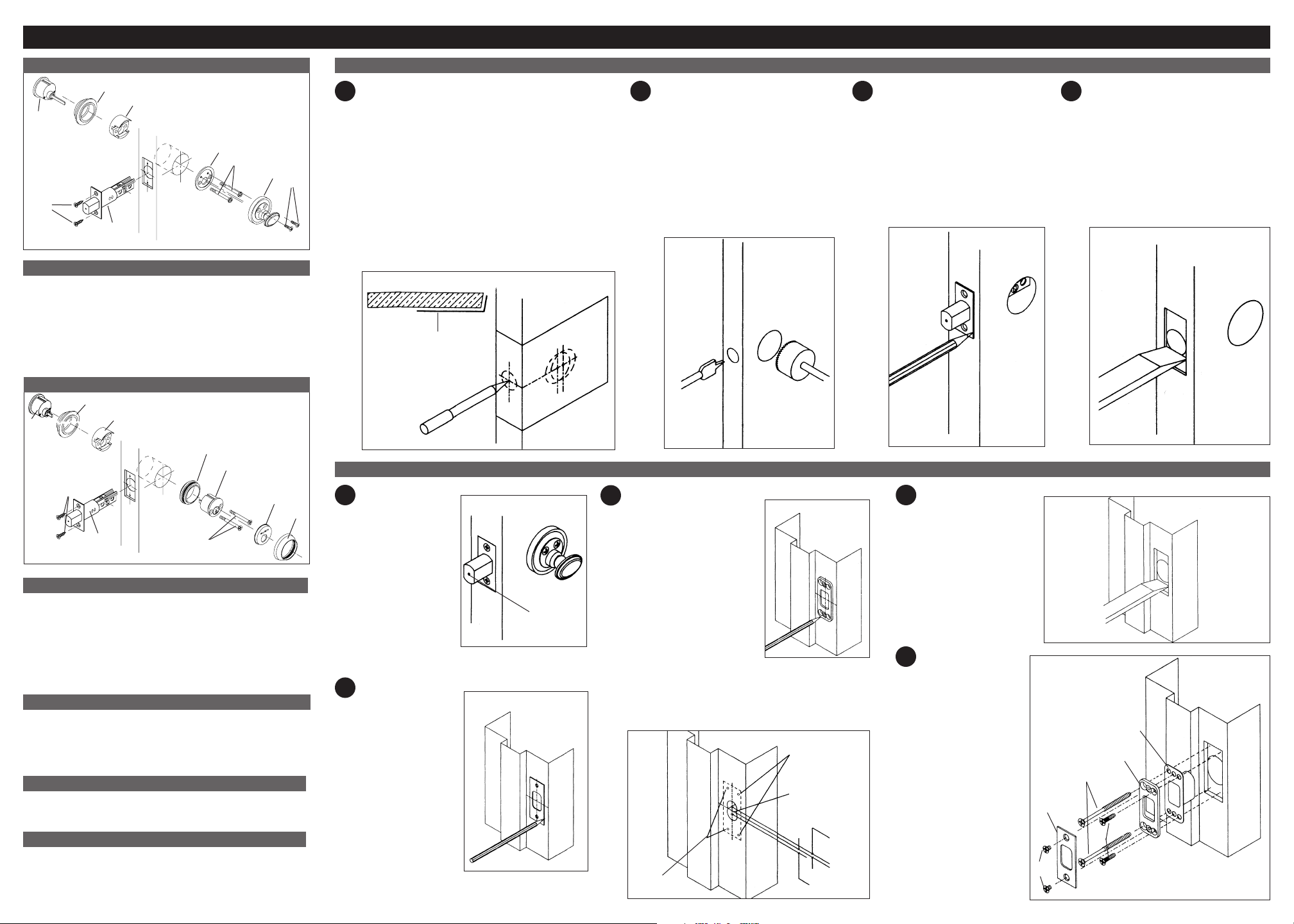
Exploded View Single Cylinder Deadbolt
7.
9.
8.
4.
6.
5.
Parts Enclosed
1. 2 each #8-32 x 5/8” Oval Head
Machine Screws
2. 1 Turnpiece Trim
3. 2 each #10-32 x 1-7/8” Pan Head
Machine Screws
4. 1 Turnpiece Mounting Plate
Note: See Strike Installation section for strike parts listing.
5. 1 Adjustable Backset Deadbolt
6. 4 each #8-3/4” Flathead
Combination Screws
7. 1 Outside Cylinder Collar
8. 1 Outside Cylinder
9. Screw Guide
Exploded View Double Cylinder Deadbolt
8.
9.
10.
Door Preparation
1
To position template fold enclosed template on line and
locate on door at desired height (usually 5 ½” above
center of latchset.) If you have a new door that is not
3.
2.
1.
already cut-out, please follow these instructions. If your
door is pre-bored, please proceed to Single Cylinder
& Double Cylinder Deadbolt Installation-Step 1. If the
door is beveled, place the folded edge on low side
of bevel as shown in the illustration. Determine door
2 4
Drill the 1-5/8” diameter face bore
(A) through the door and 1” diameter
edge bore (B) 3-1/2” deep for a 2-3/8”
backset or 3-7/8” deep for a 2-3/4”
backset. The bolt accommodates both
3
Insert deadbolt into edge of door.
While holding faceplate, trace outline
of the faceplate onto the door edge.
Mark screw hole centers and drill with
a 1/8”drill.
size backsets.
Caution: Re-check hole locations
before drilling.
Chisel out the area marked for the
faceplate to a depth of 5/32” or until
faceplate is flush with door edge.
Proceed now to the Strike Installation.
thickness and backset (2-3/8” or 2-3/4”). Mark the door
for face and edge bores.
Top view of door
A
Template
A
B
B
Edgebore
Facebore
5.
4.
7.
6.
3.
2.
Parts Enclosed
1. 1 Inside Collar
2. 1 Cylinder Cover
3. 2 each #10-32 x 2-1/4” Flat Head
Machine Screws
4. 1 Inside Cylinder
5. 1 Threaded Collar
Note: See Strike Installation section for strike parts listing.
6. 1 Adjustable Backset
7. 4 each #8-3/4” Flathead
Combination Screws
8. 1 Outside Cylinder Collar
9. 1 Outside Cylinder
10. Screw Guide
Tools Needed: Only Required for Doors Without Cutout
If your door is not pre-bored, see reverse side of instructions
for door preparation.
1. Pencil 3. 1/2” or 3/4” wood chisel
2. 1-5/8” diameter hole saw 4. Drill and assorted bits: 1/8”, 5/32” and 1”
Tools Needed: Doors Prepared with 1-5/8” Cutout
1. No. 2 and No. 3 phillips screwdrivers 3. Two pliers for Double Cylinder
2. Measuring device 4. Flathead Screwdriver
Optional Deadbolt Accessories for 1-3/8” Doors
When installing deadbolts on 1-3/8” thick doors, optional Cylinder Collar
Spacers are required (No. 8097). Consult your Baldwin distributor for
further details.
TEAR HERE FOR ENGLISH. TEAR HERE FOR ENGLISH.
Strike Installation
1
1.
Close door and
extend deadbolt
FIG. 1
several times
against door frame.
Strike centering
indicator will leave
a center mark on
the door frame
(Fig. 1).
2
Position strike plate
FIG. 2
Centering
indicator
on center mark.
Align and trace
outside of strike and
mounting screws
onto the door frame
(Fig. 2).
3
Using reinforcing strike
as a template, mark
locations for reinforcing
screws (Fig 3). Drill two
5/32” dia. pilot holes for
the 3” long screws and
two 1/8” dia. pilot holes
for the #8 x 3/4” screws.
Mark drill points 5/16”
above and below
centering point. Bore
two 1” dia. holes 1-1/4”
deep at these points.
Chisel out holes for dust
box (Fig. 4).
FIG. 4
Drill 5/32” dia. pilot
holes for 3” screws.
FIG. 3
Drill 1/8” dia. pilot
holes for # 8 screws.
Bore 1” dia. hole
above and below
centering point.
5/16” above
center point.
center line
5/16” below center point.
4
Mortise 7/32” deep
or until the strike box,
reinforcing strike and
strike plate fits inside
mortise and flushwith the
door frame (Fig. 5).
5
Install strike as
illustrated.
1. Dust Box
2. Reinforcing Strike
3. #8 x 3/4” Combination
6. Screws (2)
4. 3” Reinforcing
6. Screws* (2)
5. Strike Plate
6. #8-32 x 1/4”
6. Machine Screws (2)
FIG. 5
* Note: Lubricant
recommended
when installing 3”
reinforcing screws.
1
2
4*
5
3
6
Page 2
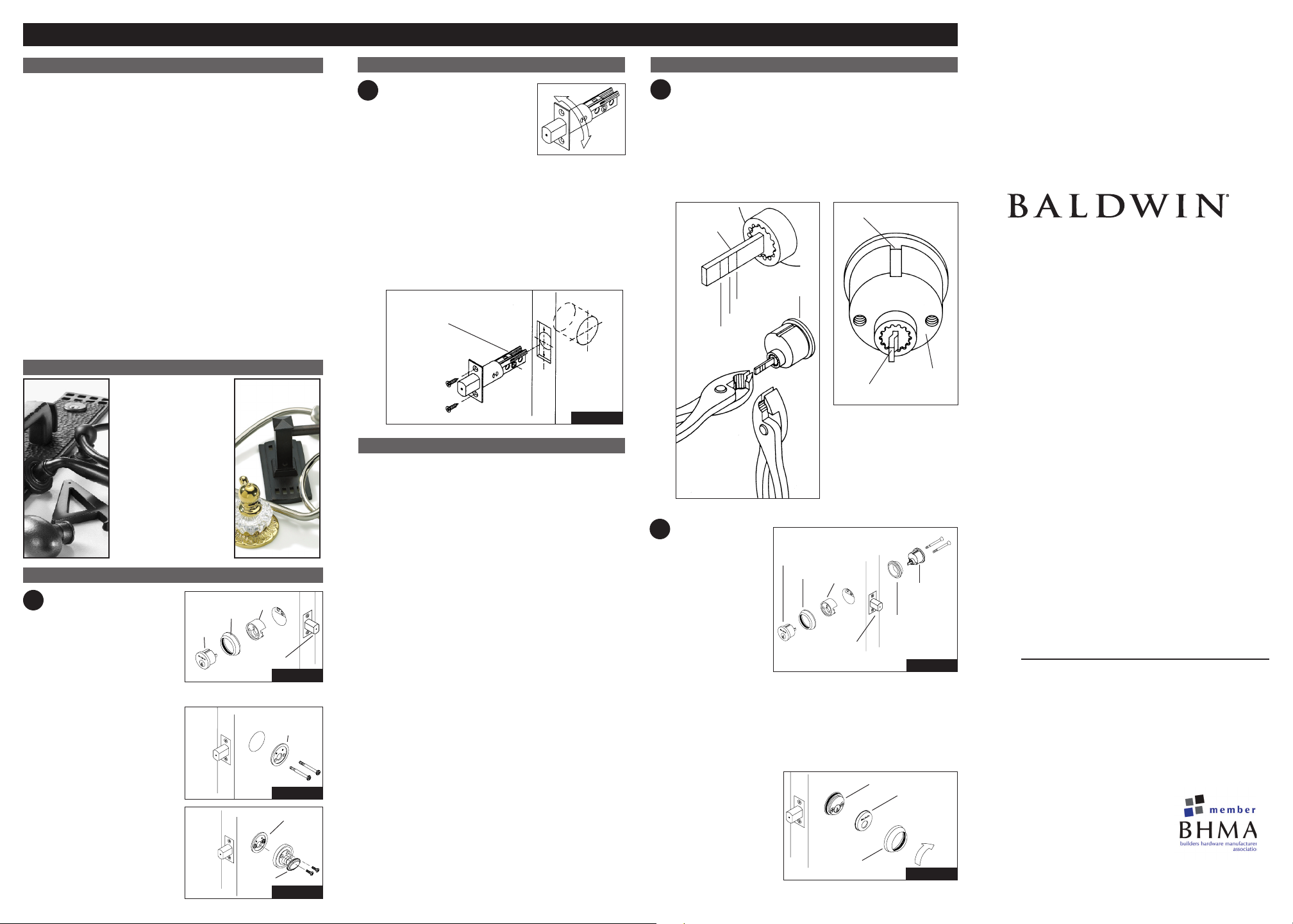
1-5/8” Deadbolt Preparation
Congratulations!
With your purchase of The Images Collection solid brass deadbolt, you’re
among a group of discerning individuals who know the intrinsic value of
selecting the finest – Baldwin.
Images entrance locksets, interior latchsets, and deadbolts coordinate beautifully,
enabling you to carry a specific design theme throughout your home.
Our step-by-step installation instructions will help guide you through your
project quickly and easily.
Before you begin your installation, read and understand the installation
instructions and marking templates. If you have any questions, please do not
hesitate to contact our Baldwin Technical Services Department at
1-800-566-1986. We’re here to help!
NOTE: Failure to use all recommended components will void Grade 1 rating.
We thank you for your Baldwin purchase and wish you the fullest
enjoyment of your Baldwin Handleset.
Technical Services Support
1-800-566-1986
Hours: 8 a.m. to 8 p.m. E.S.T. – Monday - Friday
10 a.m. to 6 p.m. E.S. T. – Saturday
Remember Baldwin
With the completion of
your project, remember that
Baldwin quality hardware
products are available for
all your decorating and
remodeling needs. Matching
knob and leversets for
interior doors, beautiful bath
accessories, and a complete
selection of cabinet and door
enhancing hardware are all
available from your Baldwin
retailer.
Single Cylinder Assembly
Collar
Screw
Guide
Extended
Deadbolt
Turnpiece
Trim
OUTSIDE
Mounting
Plate
INSIDE
Mounting Plate
INSIDE
A. Extend deadbolt using
1
flathead screwdriver. Keeping
tailpiece vertical, insert cylinder
through collar and screw guide
into deadbolt. The arrow on
the screw guide must be on the
outside and pointing up. Hold in
place. Do not insert key during
this procedure (Fig. 1).
B. Place turnpiece mounting
plate on inside of door as shown.
Attach cylinder using two #1032 x 1-7/8” pan head machine
screws. Insert screws through
mounting plate, deadbolt, screw
guide and collar into the cylinder.
Tighten all screws (Fig. 2).
C. Place turnpiece trim over
mounting plate. Insert tailpiece
into turn piece. Attach trim to
mounting plate with two #8-32
x 5/8” oval head machine
screws. Tighten screws
(Fig 3).
TEAR HERE FOR ENGLISH.
FIG. 1
Cylinder
FIG. 2
FIG. 3
Installing Deadbolt
A. The deadbolt supplied with this
1
unit has an adjustable backset
feature. It will be set at 2-3/8”
backset. To adjust to 2-3/4” backset,
grasp body and twist faceplate/
bolthead assembly 180° until it stops. Unit is now ready
for installation in a 2-3/4” backset configuration.
B. Insert deadbolt. Install with two #8 x 3/4” flat head combination screws provided (see diagram for proper positioning).
Ensure deadbolt head is extended throughout installation
procedure.
Install deadbolt with both long slots
on latch body in upper position.
INSIDE
Warranty Information
Limited Lifetime Mechanical Warranty – Baldwin warrants
that each Baldwin product shall be free from mechanical defects at
the time of delivery and for the lifetime of the product or as long as
you own your home.
Limited Lifetime Finish™ Warranty – The Baldwin Lifetime
Finish™ uses advanced finishing technology (physical vapor
deposition) to create a finish highly resistant to the effects of
weather and normal wear and tear. The Limited Lifetime Finish
Warranty on Lifetime Finish™ products covers the original
purchaser for as long as you own your home.
Limited Finish Warranty – The finish on Baldwin products
(excluding Lifetime Finish and living finish products) is protected by
a durable topcoat designed to maintain the beauty and quality of the
Baldwin product. The Baldwin Limited Finish Warranty covers the
original purchaser for five years from date of purchase for interior
use and one year for exterior use.
Living Finishes – Due to the nature of Baldwin living finish
products, they will wear over time and may already have begun the
process before reaching your home. No finish warranty is offered
on living finish products, which are designed to age and improve
over time. Living finishes include raw brass, oil rubbed bronze,
stainless steel, and other non-lacquered or non-PVD finishes.
Refer to www.baldwinhardware.com for a complete warranty
statement.
Double Cylinder Assembly
1
A. Carefully break off cylinder
tailpiece at required mark for
your door thickness.
Caution; use two pairs of pliers
B. Align tailpiece with slot.
Keep tailpiece vertical and
curved toward right side of
the hole as illustrated.
as shown or tailpiece will be
damaged.
Tailpiece
Cylinder
1-3/4”
2”
2-1/4”
A. Extend deadbolt
2
using flathead
screwdriver.
Keeping tailpiece
FIG. 4
Outside Cylinder
Collar
vertical and toward
the right side of
hole, insert outside
cylinder through
collar and into the
deadbolt. Align
slot of inside cylinder with notch in threaded collar. Keeping
tailpiece vertical and curved toward the right side of hole, insert
inside cylinder with threaded collar into the deadbolt. Attach
cylinders using two #10-32 x 2-1/4” flat head machine screws.
Tighten screws. Do not insert key during this procedure. (Fig.4)
B. Align cylinder cover
over inside cylinder.
Screw on decorative
cylinder collar.
Congratulations! Your
installation is now
complete!
Slot
Tailpiece
Screw
Guide
Extended
deadbolt
Cylinder collar
Threaded
Collar
Inside Cylinder
TEAR HERE FOR ENGLISH.
Cylinder
Inside
Cylinder
OUTSIDE
Cylinder
cover
INSIDE
1-5/8” Collar
Auxiliary Deadbolt
Installation Instructions
©2009 Baldwin Hardware Corporation
Reading, PA 19611
PK-1092-T (1/09)
 Loading...