

Page 1
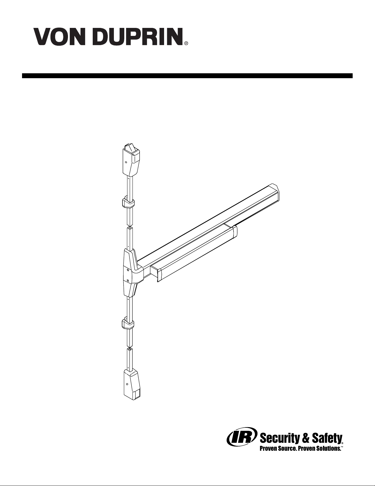
PARTS MANUAL
3327A/3527A SERIES
EXIT DEVICES
JUNE 2005
PM3327A3527A_b
VD-4050
3527A SHOWN
Copyright © 2005 Ingersoll-Rand. All right s reserved.
Page 2

INDEX
3327A/3527A Fire and Panic Devices
Basic Device ............................................................................................................................... 4-5
Vertical Rods and Latches........................................................................................................... 6-7
LBR Fire Latch Kit.......................................................................................................................... 8
Baseplate Assembly....................................................................................................................... 9
V ariations of the Basic Device
CD (Cylinder Dogging)........................................................................................................ 4-5
HD-EL (Hex Dogging/Electric Latch Retraction) .................................................................. 10
EL (Electric Latch Retraction) ..............................................................................................11
SS (Signal Switch)...............................................................................................................11
RX (Request to Exit) .......................................................................................................12-13
LX (Latch Bolt Monitoring) ...............................................................................................12-13
ALK Exit Alarm Kit ..........................................................................................................14-15
General Information
Introduction..................................................................................................................................... 2
How to Order .................................................................................................................................. 2
Part Number Changes .................................................................................................................... 2
Finishes ......................................................................................................................................... 3
Outside Trim Functions .................................................................................................................. 3
Strikes............................................................................................................................................ 3
INTRODUCTION
This manual contains a listing of replaceable parts and assemblies for the 3327A/3527A Panic Exit Hardware
Devices. (3327A Series and 3527A Series devices are almost identical. The 3327A Series has a grooved
case; the 3527A Series has a smooth case.)
HOW TO ORDER
Some parts are sold separately . Other items are available as p art of a kit or multiple quantity package.
For the best possible service when ordering replacement parts or assemblies, please provide the following
information:
• Part number or assembly number
• Description
• Quantity needed
• Finish desired (if available finished)
• Date of original purchase (if known)
T o find out the name of your local V on Duprin distributor or sales representative, cont act:
Von Duprin Division
Ingersoll-Rand Company
2720 T obey Drive
Indianapolis, Indiana 46219
Phone: (800) 999-0408
Fax: (800) 999-0328
Website: www .vonduprin.com
PART NUMBER CHANGES
This manual reflects the product as sold in June 2005. Because of changes to the product and/or
manufacturing process, part numbers can change.
Page 2 of 14
PM3327A3527A_a
Page 3
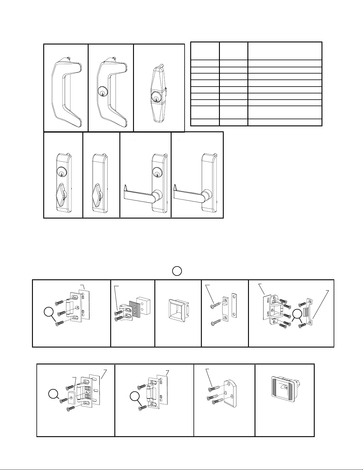
OUTSIDE TRIM FUNCTIONS
386DT***
386NL**
388NL-OP****
33A/35A SERIES FINISHES
U.S. Std
Reference
BHMA
Reference Description
US3
US4
US10
US15
US26
US26D
US28
313AN
315AN
360T
360T-BE* 360L
360L-BE*
360L-DT***
* “BE” (Blank Escutcheon) no cylinder used - lever always active
** “NL” (Night Latch) rigid lever - key retracts latch bolt
*** ”DT” (Dummy Trim) rigid lever for pull operation
**** “NL-OP” (Optional Pull) needs to be added
605
606
612
619
625
626
628
710
71 1
Polished Brass
Dull Brass
Dull Bronze
Satin Nickel
Polished Chrome
Dull Chrome
Anodized Alum. (Clear)
Anodized Alum. (313)
Dark Bronze
Anodized Alum. (Black)
Metal Door Screw Package PKGSRV .1023 (Pkg of 10)
STANDARD STRIKES
Adjusting Shim
945521
1
299 (T op) Strike - S t andard
Single or Double Door
Panic Exit Hardware
(T op) Strike
Screw Pkg
900266
266
(Bottom) Strike
1
Wood Door Screw 964291 (Qty of 1)
Screw Pkg
900263
304L
248L-4
(Bottom) Strike
OPTIONAL STRIKES FOR PANIC EXIT HARDWARE
Adjusting Shim 970321
Strike Plate
970323
1
299 (T op) Strike - S t andard
Single or Double Door
Panic Exit Hardware
Adjusting Shim
945521
1
264 (Top) Strike - Single
Door Panic Exit Hardware
Screw Pkg
900252
260U (T op) Strike
For Flush Transom
Applications Only
Adjusting Shim 945521
Strike Hook 969300
1
499F (T op) Strike - Supplied
with LBR Fire Latch/Strike Kit
385A
(Bottom) Strike
PM3327A3527A_a
Page 3 of 14
Page 4
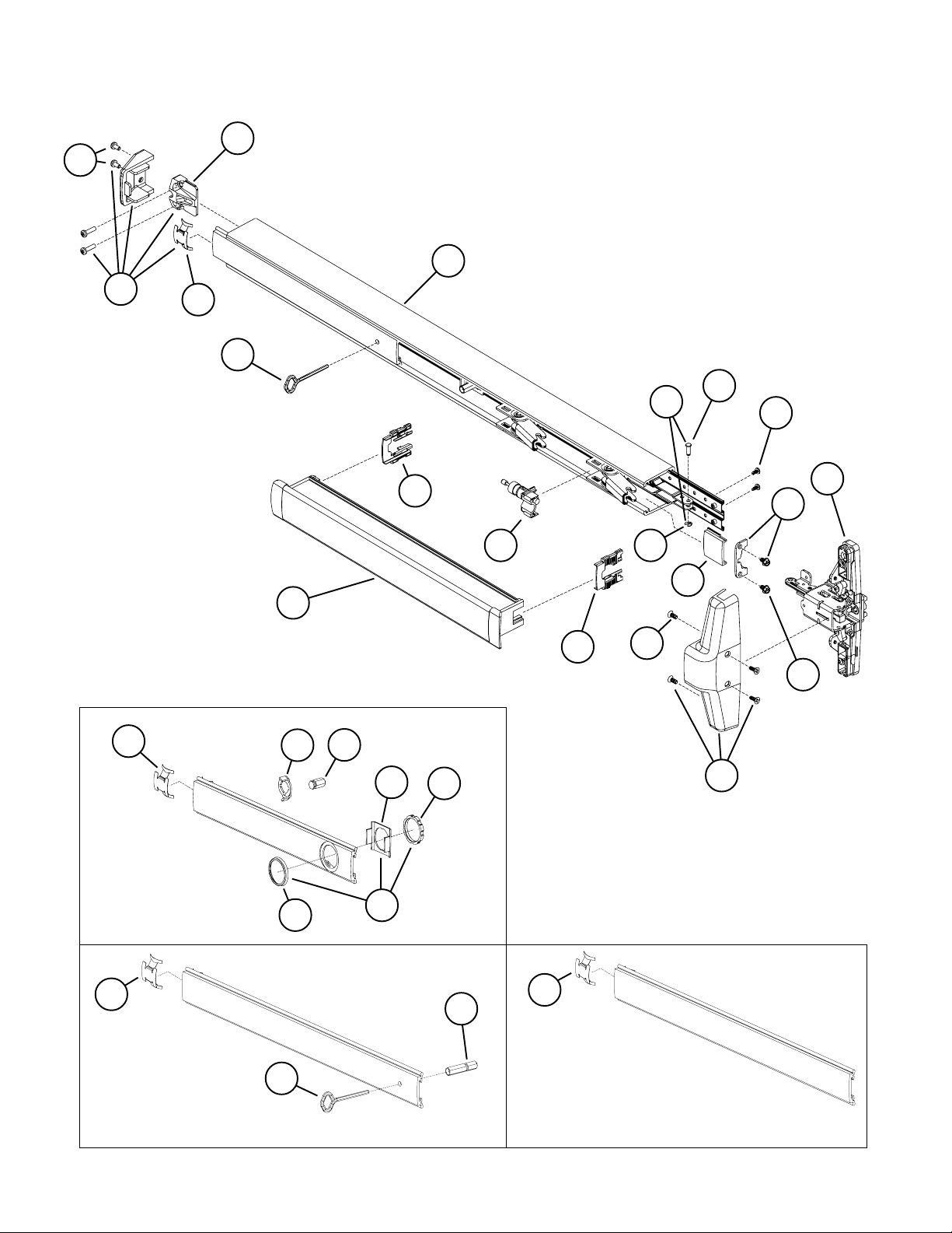
3327A/3527A PANIC AND 3327A-F/3527A-F FIRE EXIT DEVICE
7A
8
9
7
7B
7B
1
10A
10
17
16
6
17
4
5
10B
14
18
11
13
12
12A
P ANIC ONL Y
CD Conversion Kit
33A Series - 050115
35A Series - 050132
7B
P ANIC ONL Y
Hex Dogging Kit
33A Series - 050114
35A Series - 050117
Page 4 of 14
15
3A
3
3B
3C
7B
2
Fire or Less Dogging
1
Cover Plate Kit
33A Series - 050133
35A Series - 050109
PM3327A3527A_a
Page 5

3327A/3527A PANIC AND 3327A-F/3527A-F FIRE EXIT DEVICE
Item No. Quantity Part No. Description Finish
1 900619 33A/35A Series Mounting Pkg. (1-3/4 & 2-1/4)
1 1 090085 227 Dog Key 5/32” Hex (Pkg of 10)
1 1 090005 227 Dog Key 5/32” Hex (Pkg of 2)
2 1 090040 Hex Dog Shaft (Pkg of 2)
3 1 107813 Cylinder Mounting Pkg X
3A 1 050525 Cylinder Collar X
3B 1 050490 Cylinder Locating Washer - CD/SS
3C 1 050526 Cylinder Locknut
4 1 090046 CD Dogging Plug (Pkg of 2)
5 1 090045 CD Actuator Arm (Pkg of 2)
6 1 *PBKIT 33A/35A Series Push Bar Retrofit Kit - 3’ Door X
6 1 *PBKIT 33A/35A Series Push Bar Retrofit Kit - 4’ Door X
7 1 050014 33A/35A Series Series End Cap Kit X
7A 1 050524 Impact Resistant End Cap Bracket
7B 1 090036 Cover Plate Anti-rattle S pring (Pkg of 10)
8 1 900597 Device End Cap and C/Case Screw Pkg. X
9 1 050486 33A Series Mechanism Case - 3’ Door X
9 1 050487 33A Series Mechanism Case - 4’ Door X
9 1 050488 35A Series Mechanism Case - 3’ Door X
9 1 050489 35A Series Mechanism Case - 4’ Door X
10 1 050529 Control Link Pin & Ret. Ring
10A 1 090031 Control Link Pin (Pkg of 10)
10B 1 090107 Retaining Ring (Pkg of 10)
11 2 090037 #8-32 x 3/8” Baseplate Screw (Pkg of 10)
12 1 050530 Mechanism Case Bracket Kit
12A 2 090073 Mechanism Case Bracket Screw (Pkg of 10)
13** 1 050404 3327A/3527A Center Case Less Cover
14 1 050474 33A Series Cover Plate - C. Case Side X
14 1 050475 35A Series Cover Plate - C. Case Side X
15 1 050484 3327A/3527A Center Case Cover Kit X
16 1 050491 Shock Absorber & Holder Assembly
17 2 090049 Push Bar Guide (Pkg of 10)
18 4 900892 Center Case Cover Screws (Pkg of 4) X
X in “Finish” column designates finished items; finish must be specified when ordering.
* To order , specify device type, size, and finish. Example: PBKIT 33A 3’ US28
** Device mounting screws 900619 included.
PM3327A3527A_a
Page 5 of 14
Page 6

3327A/3527A VERTICAL RODS AND LATCHES
3
11
8
1
19
12
13
19
7
15
9
10
17
Pullman Latch
Kit Less Cover
4
050402
Panic Device Only -
Includes Mtg Screws
6
16
16
10
1
19
Page 6 of 14
9
10
5
Extension Rod Kits
20
3327A 12” 051801
3527A 12” 051809
3327A 36” 051802
6
3527A 36” 051810
(36” extension rod kits
7
15
2
11
17
8
12
include items 6 & 9)
14
PM3327A3527A_a
Page 7

3327A/3527A VERTICAL RODS AND LATCHES
Item No. Quantity Part No. Description Finish
1 2 034902 325 Sex Bolt Package (Pkg of 2) X
2 1 050401 33/3527A Bottom Latch Kit Less Cover
3 1 050400 33/3527A Top Latch Kit Less Cover
4 1 050512 3327A Top Rod Kit X
4 1 050513 3527A Top Rod Kit X
5 1 050514 3327A Bottom Rod Kit X
5 1 050515 3527A Bottom Rod Kit X
6 2 105952 33/3527A Rod Guide Pkg X
7 1 900589 Latch Mounting Package (Pkg of 4)
8 2 900850 Latch Case Cover Screw (Pkg of 2) X
9 2 900565 Rod Guide Mounting Package
10 4 090054 Rod Roll Pin (Pkg of 10)
11 6 090055 Housing Guide Pin (Pkg of 10)
12 2 090065 Bolt Return Spring (Pkg of 10)
13 1 090056 Top Latch Compression S pring (Pkg of 10)
13 1 090057 PL Top Latch S pring (Pkg of 10)
14 1 090058 Bottom Latch Case Spring (Pkg of 10)
15 2 090067 Rod Connector - Latch (Pkg of 2)
16 2 090068 Rod Connector - Center Case (Pkg of 2)
17 2 050496 Latch Case Cover Kit w/Screws X
18 1 090076 Aux. Bolt Spring (Pkg of 10)
19 2 050546 Latch Case Mtg. Bracket
20 1 090075 Rod Extension Connector (Pkg of 4)
X in “Finish” column designates finished items; finish must be specified when ordering.
PM3327A3527A_a
Page 7 of 14
Page 8

33/3527A-F LBR (LESS BOTTOM ROD) FIRE LATCH KIT
Item No. Quantity Part No. Description Finish
1 1 050171 LBR Fire Latch/S trike kit
2 1 050509 LBR Fire Strike Plug
3 1 113334 LBR Center Case Hole Plug
3
1
Note: 499F Strike (not shown)
is included with P/N 050171
2
Page 8 of 14
PM3327A3527A_a
Page 9

3327A/3527A PANIC DEVICE BASEPLATE ASSEMBLY
Item No. Quantity Part No. Description Finish
1 1 090043 Dogging adapter (Pkg of 2)
2 1 090042 Dogging adapter spring (Pkg of 2)
3 1 090041 Dogging spring (Pkg of 2)
4 1 090040 Hex dogging shaft (Pkg of 2)
5 1 090044 Dogging hook (Pkg of 2)
6 1 090039 Latch return spring (Pkg of 10)
7 4 090038 Rubber bumper (Pkg of 4)
8 1 050491 Shock absorber
7
8
6
1
2
33/3527A-F FIRE DEVICE BASEPLATE ASSEMBLY
Item No. Quantity Part No. Description Finish
1 4 090038 Rubber bumper (Pkg of 4)
2 1 090039 Latch return spring (Pkg of 10)
3 1 050491 Shock absorber
4
5
3
1
2
PM3327A3527A_a
3
1
Page 9 of 14
Page 10

HD-EL3327A/HD-EL3527A HEX DOGGING/ELECTRIC LATCH
RETRACTION OPTION - PANIC DEVICE ONLY
Item No. Quantity Part No. Description Finish
1 1 050531 EL Dogging Rod Kit - 3’ Device
1 1 050532 EL Dogging Rod Kit - 4’ Device
2 1 1 10388 EL 6 ’ Cable and Connector
3 1 050534 EL Potted Circuit Breaker
4 1 050536 HD-EL Solenoid
5 1 050537 HD-EL S olenoid Plunger
6 1 050538 EL Dogging Rod Retainer
7 1 050539 EL Receptacle Connector - 2 Position
8 2 050540 EL Female T erminal
9 1 050541 HD-EL Dog Screw
10 1 050542 HD-EL Solenoid Bracket
11 1 050543 HD-EL Dogging S pring
12 1 990599 EL Plug Connector - 2 Position
13 1 990857 EL Receptacle Connector - 3 Position
14 1 990858 EL Plug Connector - 3 Position
* 1 050384 HD-EL Conversion Kit - 3'
* 1 050385 HD-EL Conversion Kit - 4'
*Kit includes items 1-1 1 plus new control link, retaining ring, and baseplate screws.
9
4
3
2
7
8
12
13
14
10
6
5
11
1
Page 10 of 14
PM3327A3527A_a
Page 11

EL3327A/EL3527A ELECTRIC LATCH RETRACTION OPTION
Item No. Quantity Part No. Description Finish
1 1 050531 EL Dogging Rod Kit - 3’ device
1 1 050532 EL Dogging Rod Kit - 4’ device
2 1 1 10388 EL 6 ’ Cable and Connector
3 1 050534 EL Potted Circuit Breaker
4 1 050535 EL Solenoid Assembly
5 1 050538 EL Dogging Rod Retainer
6 1 050539 EL Receptacle Connector
7 2 050540 EL Female T erminal
8 1 990599 EL Plug Connector - 2 Position
9 1 990857 EL Receptacle Connector - 3 Position
10 1 990858 EL Plug Connector - 3 Position
* 1 050070 EL Conversion Kit - 3’
* 1 050078 EL Conversion Kit - 4’
*Kit includes items 1-7 plus new control link pin, retaining ring, and baseplate screws.
4
3
6
2
7
8
9
10
5
SS3327A/SS3527A (SIGNAL SWITCH) OPTION
Item No. Quantity Part No. Description Finish
1 1 050544 SS Cable
2 1 050545 SS Housing
3 1 990601 SS Plug Connector - 6 Position
4 1 990602 SS Receptacle Connector - 6 Position
1
1
PM3327A3527A_a
3
4
2
Page 11 of 14
Page 12

3327A/3527A LX (LATCH BOLT MONITOR) &
RX (REQUEST TO EXIT) OPTIONS
1
7
8
LX Switch
Wire Colors
Violet, Gray, White
(for Low Current
Violet, Gray, Black)
RX Switch
2
Wire Colors
Red, Y ellow, Blue
(for Low Current
Green, Y ellow, Blue)
7
Page 12 of 14
PM3327A3527A_a
Page 13

3327A/3527A LX (LATCH BOLT MONITOR) &
RX (REQUEST TO EXIT) OPTIONS
Item No. Quantity Part No. Description Finish
1 1 050254 LX Switch Kit 3’ Device
1 1 050255 LX Switch Kit 4’ Device
1 1 050247 LX-EL Switch Kit
1 1 050283 LX-LC (Low Current) Switch Kit 3’ Device
1 1 050285 LX-LC (Low Current) Switch Kit 4’ Device
1 1 050287 LX-LC-EL (Low Current) Switch Kit
2 1 050251 RX Switch Kit
2 1 050281 RX-LC (Low Current) Switch Kit
3 1 050256 LX-RX Switch Kit 3’ Device
3 1 050257 LX-RX Switch Kit 4’ Device
3 1 050259 LX-RX-EL Switch Kit
3 1 050289 LX-RX-LC (Low Current) Sw. Kit 3’ Device
3 1 050291 LX-RX-LC (Low Current) Sw. Kit 4’ Device
3 1 050293 LX-RX-LC-EL (Low Current) Switch Kit
2 & 4 1 050270 RX-2 Switch Kit
4 1 050271 RX-AUX Switch Kit
5 1 964558 8-32 x 5/16” PPHMS
6 1 964019 #8 Washer
7 1 090099 Pine Tree Clip (Pkg of 10)
8 1 971091 LX Actuator
LX-RX Switch
3
7
Wire Colors
Red, Y ellow, Blue
(for Low Current
Green, Y ellow, Blue)
Wire Colors
Violet, Gray, White
(for Low Current
Violet, Gray, Black)
4
6
5
Wire Colors
Red, Y ellow, Blue
(for Low Current
Green, Y ellow, Blue)
RX-AUX Switch
PM3327A3527A_a
Page 13 of 14
Page 14

33A/35A ALK EXIT ALARM KIT
Item No. Quantity Part No. Description Finish
1 1 111795 ALK PCB Assembly
2 1 050525 Cylinder Collar X
3 1 969122 ALK Alarm Device Sign
4 1 969349 ALK Arming Label
5 1 969350 ALK Disarming Label
6 1 969354 Retainer Nut
7 1 970594 ALK Cylinder Sp acer
8 1 090036 Cover Plate Anti-rattle spring (Pkg of 10)
9 1 971556 ALK Switch Actuator
10 1 971557 ALK Cylinder Bracket
11 1 990637 ALK Battery
12 1 050406 33A Series ALK Cover Plate Kit X
12 1 050407 35A Series ALK Cover Plate Kit X
X in “Finish” column designates finished items; finish must be specified when ordering.
EMERGENCY EXIT ONLY
ALARM WILL SOUND
12
2
8
10
7
1
11
3
A
M
R
A
S
I
D
R
M
Page 14 of 14
9
5
6
4
PM3327A3527A_a
 Loading...