

Page 1
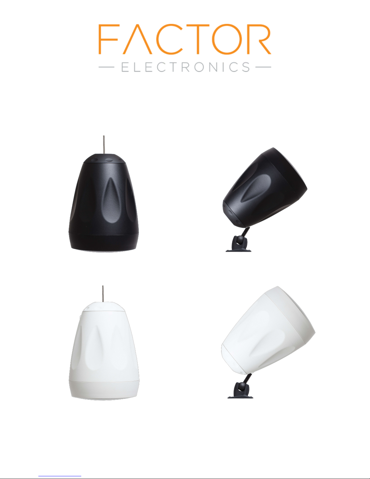
VERSA-6.5W and VERSA-6.5B
Pendant/Projection Speaker System
www.factorelectronics.com [email protected]
Page 2
Introduction
Congratulations and thank you for purchasing a Factor Electronics product. The Factor
Electronics VERSA-6.5 speaker system provides a high quality soultion for paging and
background music. The VERSA-6.5 can be hung from ceilings as a pendant style speaker
or mounted to any hard surface using the included swivel ball mount and used as a
projection speaker. The VERSA-6.5 is very easy to install and operate. Please read this
entire manual to get the most from your VERSA-6.5 speaker system.
Unpacking
The VERSA-6.5 includes the following parts:
1 x VERSA-6.5 speaker (white or black)
2 x Top finishing caps (one for pendant mounting and one for bracket mounting)
1 x 15' aircraft type hanging cable with connectors
1 x Bag containg screws and loop hanging bolt
1 x Ball/swivel mounting bracket
1 x VERSA-6.5 manual
Installation:
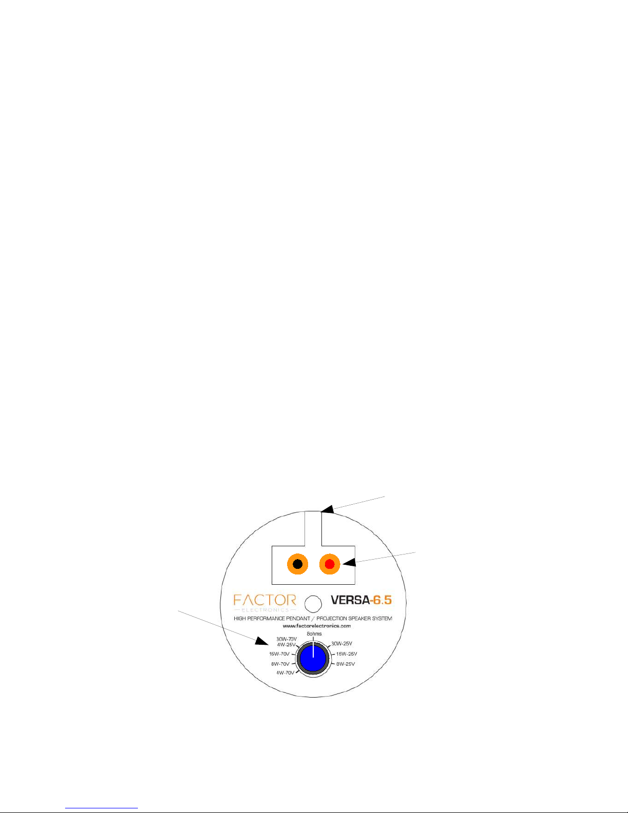
The VERSA-6.5 speakers can be used with constant voltage 25/70V amplifiers or 4/8ohm
stereo amplifiers. A wattage tap dial is provided on the back panel which provides the
following wattage taps: 30W, 15W, 8W, 4W 25Volt or 70Volt and a 8ohm transformer
bypass setting is also provided. Always make sure that the wattage of all speakers
combined does not exceed the wattage of the amplifier. Example: 10 x VERSA-6.5
speakers tapped at 15W/70V =150watts. Always add 30% headroom in amplifier power
150watts x 1.3= 195watts. If you are unsure how to connect your speakers contact
Factor Electronics tech support at www.factorelectronics.com or email to
[email protected]. It's always best to plan out your system and wattage taps
before installation. Caution: connecting a 70V constant voltage amplifier to the VERSA-
6.5 speakers with the speaker set to 8ohms can damage both the amplifier and the
speaker. Take care to set the wattage taps properly before you hang or mount the
speakers.
Wire channel
Set the correct wattage
tap prior to installation
www.factorelectronics.com [email protected]
Speaker connection
push terminals
Page 3
Pendant Mounting:
Important:
All installation methods should be in accordance with the applicable section of the
National Electrical Code, ANSI/NFPA 70, and/or the National Fire Alarm Code ANSI/NFPA
72, as applicable. The wiring method and compartment should not interfere with the
operation of the speaker.
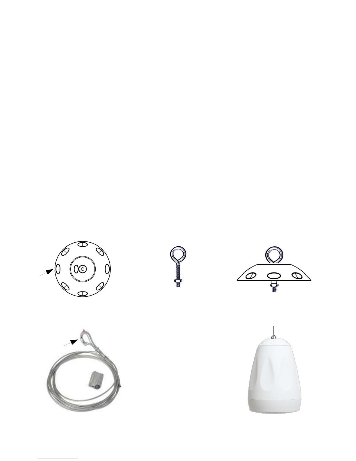
The VERSA-6.5 includes a 15' aircrat type hanging cable with connectors for each end of
the cable. Connect the cable to the ceiling or truss first and hang the cable to the
desired distance from the floor usually 10-15'. Never attach the cable to a metal mount
or truss with sharp edges. Always use a piece of soft rubber or other material between
the cable and the mount that will keep the cable from binding against the mount or
truss.
1. Connect the speaker wire to the wire-in speaker push terminals and run the wire
through the wire channel.
2.Select the pendant top with the hole in the center.
3. Remove the locking nut from the I-bolt.
4. Pass the I-bolt through the pendant top and attach the locking nut under the pendant
top.
5. Screw the I-bolt into the top of the speaker housing and tighten the lock nut.
6. With the haging cable secured to the ceiling or truss attach the gripple end of the
cable to the I-bolt.
Wire
Channel
Gripple end
Pendant top I-bolt Pendant top with I-bolt
Hanging cable Speaker with cable attached
www.factorelectronics.com [email protected]
Page 4
Projection Mounting:
Important:
All installation methods should be in accordance with the applicable section of the
National Electrical Code, ANSI/NFPA 70, and/or the National Fire Alarm Code ANSI/NFPA
72, as applicable. The wiring method and compartment should not interfere with the
operation of the speaker.
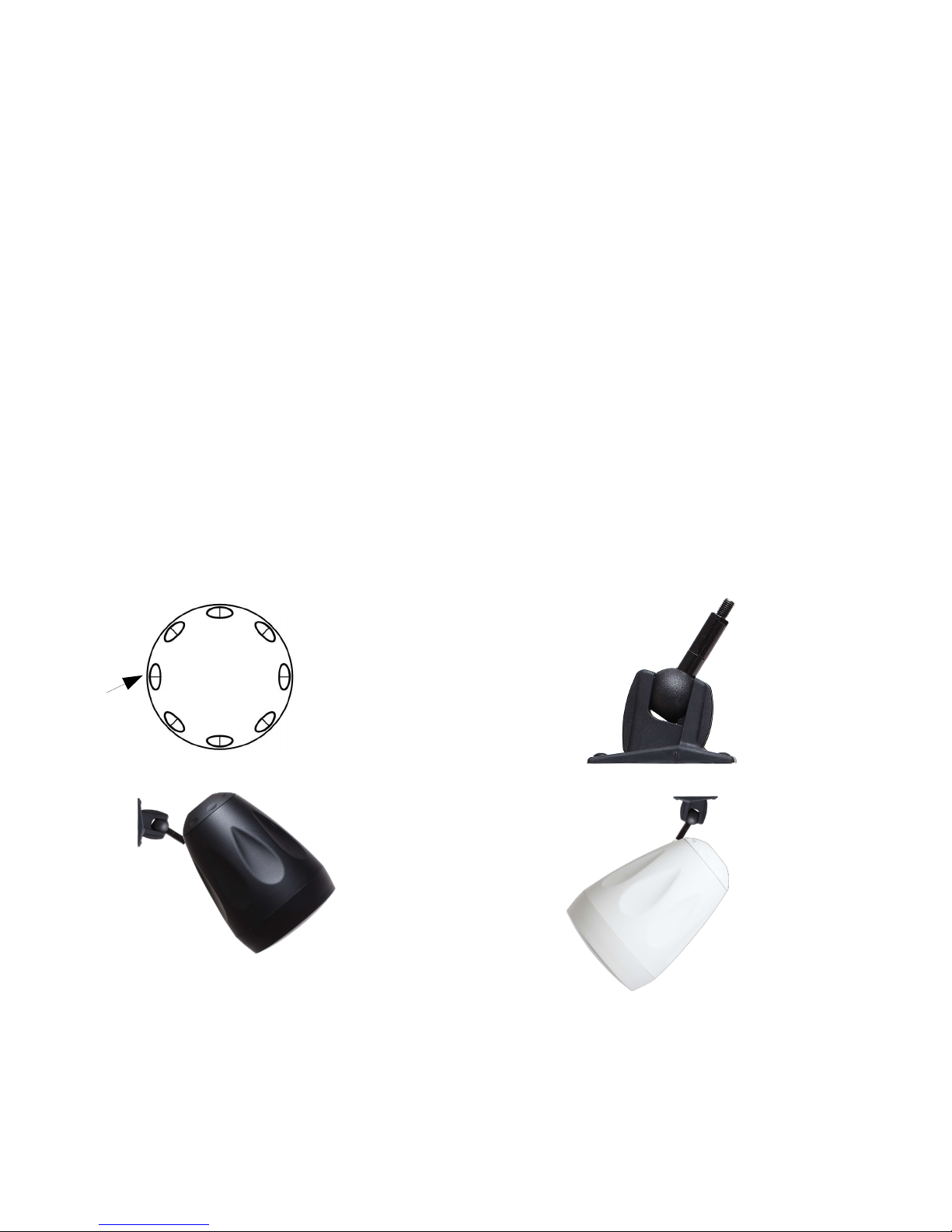
The VERSA-6.5 includes a fully adjustable ball-joint speaker mount. Angles can be
adjusted using an Allen type wrench.
1. Connect the speaker wire to the wire-in speaker push terminals and run the wire
through the wire channel.
2. Select the projection top and screw the projection top into the back plate of the
speaker. Make sure the speaker wire is directed through the wire channel.
3. Mount the speaker mount to a solid surface (walls, posts, ceiling) using heavy duty
screws. Always make sure the screws are set into a solid wood stud or solid material.
Never attach the speaker mount to drywall with drywall anchors. The surface behind the
drywall must be solid and capable of supporting the speaker and the mount.
4. Remove the threaded post on the speaker mount and attach this to the threaded
speaker mounting hole located close to the back of the speaker housing.
5. Attach the speaker to the mount and tighten.
6. Using an Allen type wrench loosen the Allen nut and adjust the angle of the speaker.
tighten the Allen nut.
Pendant top Speaker mount
Wire
Channel
In an effort to provide our customers with the latest advancements in technology, Factor Electronics Specifications are subject to change from time to
time without notice.
Contact Information
Factor Electronics 4159 McConnell Drive Burnaby B.C.Canada V5A-3J7 e-mail: [email protected] Web: www.factorelectronics.com
Warranty
Factor Electronics products (VERSA-6.5) are warranted to be free from defects in workmanship and materials for a period of (3) years without charge
for parts or labor.This warranty applies only to the original owner. The owners responsibilities are to provide proof of purchase and transportation to
the dealer the unit was purchased from or transportation to FactorElectronics. This warranty does not apply to units that have been subject to misuse,
abuse, neglect or improper installation, and does not apply to repairs or alterations made by unauthorized persons. This warranty specifically
excludes responsibility for consequential damage. Retention of your original bill of sale is required to obtain service under the terms of this warranty.
www.factorelectronics.com [email protected]
 Loading...