

Page 1
PREMIUMAUDIOVIDEOANDPOWERPRODUCTS
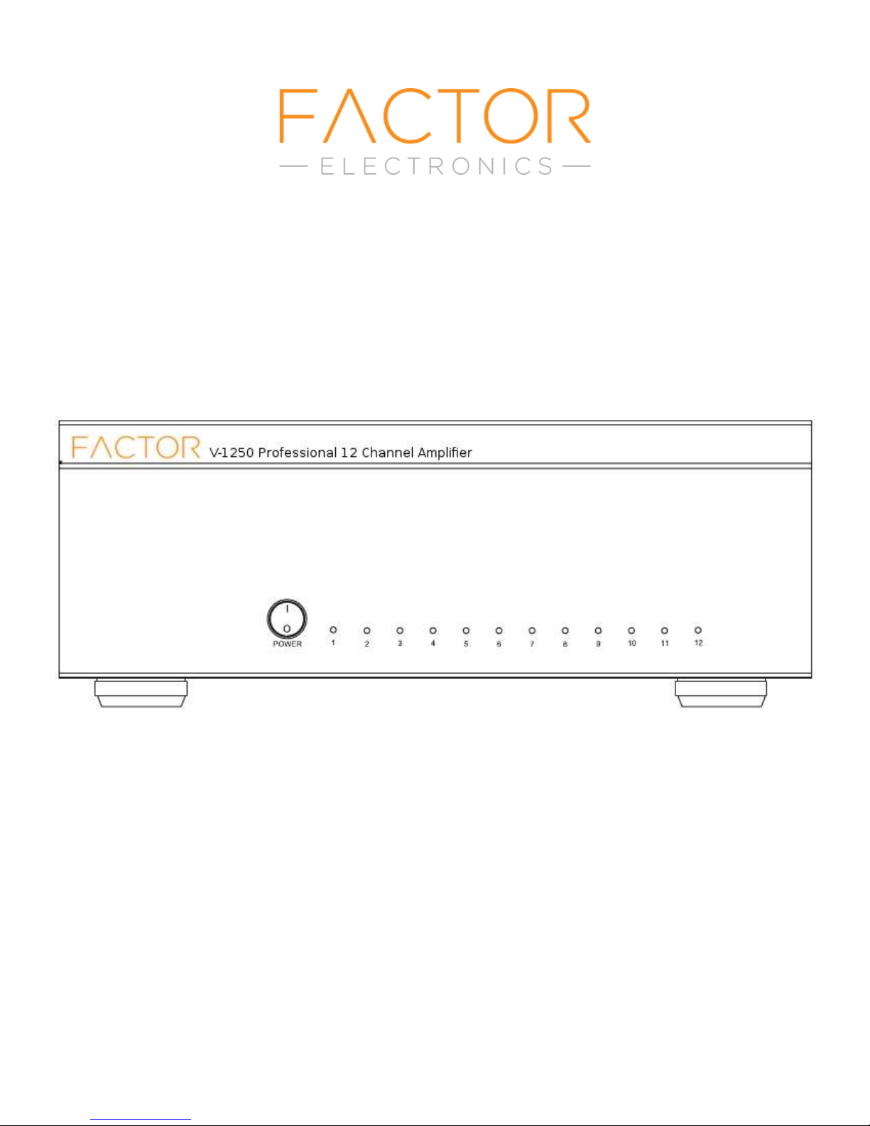
V-1250 Professional 12 Channel Amplifier
[email protected] www.factorelectronics.com
Owners Manual
Page 2

IMPORTANT NOTE: THIS OWNER'S MANUAL IS PROVIDED AS AN
INSTALLATION AND OPERATING AID. FACTOR ELECTRONICS DOES NOT
ASSUME ANY RESPONSIBILITY AS TO ITS ACCURACY AND SHALL NOT BE
LIABLE IN TORT OR CONTRACT FOR ANY DIRECT, CONSEQUENTIAL OR
INCIDENTAL LOSS OR DAMAGE ARISING FROM THE INSTALLATION, USE OR
INABILITY TO USE THIS PRODUCT.
WARNING: TO REDUCE THE RISK OF FIRE OR ELECTRIC SHOCK DO NOT
EXPOSE THIS APPLIANCE TO WATER, RAIN OR MOISTURE. THIS APPLIANCE
SHOULD NOT DAMPENED BY WATER DROPS OR SPLASHING. CONTAINERS OF
LIQUID SUCH AS VASES SHOULD NOT BE PLACED ON THIS APPLIANCE.
Immediately upon receipt, inspect the unit and shipping container for indications of improper
handling or in-transit damage. This equipment was carefully inspected and tested before
leaving the factory. Notify the Transportation Company, Wholesaler or Retailer immediately if
any damage is found. Be sure to save the carton and packing material as evidence of damage
for later inspection. DO NOT SHIP the unit back to the factory unless authorized to do so by the
factory. IN TRANSIT DAMAGES ARE NOT COVERED BY THE WARRANTY. DO NOT INSTALL OR
ATTEMPT TO OPERATE THIS UNIT IF IT HAS BEEN DAMAGED.
IMPORTANT SAFETY INSTRUCTIONS
• Read and keep these instructions.
• Heed all warnings and follow all instructions contained within this manual.
• Do not use this unit near water.
• Clean only with dry cloth.
• Do not block any ventilation openings. Install in accordance with the manufacturer’s
instructions.
• Do not install near any heat sources such as radiators, heat registers, stoves, or other
apparatus (including amplifiers) that produce heat.
• Do not defeat the safety purpose of the polarized or grounding-type plug. A polarized plug
has two blades with one wider than the other. A grounding type plug has two blades and a third
grounding prong. The wide blade or the third prong are provided for your safety. If the provided
plug does not fit into your outlet, consult an electrician for replacement of the obsolete outlet.
• Protect the power cord from being walked on or pinched particularly at plugs, convenience
receptacles, and the point where they exit from the apparatus.
• Only use attachments/accessories specified by the manufacturer.
• Unplug this apparatus during lightning storms or when unused for long periods of time.
• Refer all servicing to qualified service personnel. Servicing is required when the apparatus
has been damaged in any way, such as when the power-supply cord or plug is damaged, liquid
has been spilled or objects have fallen into the apparatus, the apparatus has been exposed to
rain or moisture, does not operate normally, or has been dropped.
• Operate the product only with the voltage specified on the unit. Fire and/or electric shock
may result if a higher voltage is used.
• Do not modify, kink, or cut the power cord. Do not place the power cord in close proximity to
heaters and do not place heavy objects on the power cord and/or the product itself, doing so
may result in fire or electrical shock.
• Replace the protective cover over the speaker terminals after installation. Do not touch the
70V speaker terminals as electric shock may result.
• Ensure that the safety ground terminal is connected to a proper ground. Never connect the
ground to a gas pipe, as a severe explosion and/or fire may result.
• Be sure the installation of this product is stable, avoid slanted surfaces as the product may
fall and cause injury, property damage, electrocution and/or fire.
• Note when the unit is turned off it is not completely disconnected from the wall AC power
outlet. Do not open the cover unless the device is unplugged from the wall AC power outlet.
[email protected] www.factorelectronics.com
Page 3

Introduction:
Congratulations and thank you for purchasing Factor Electronics products. The
Factor Electronics “V” series amplifiers are designed and built to provide ultra
reliable performance for professional background music, paging applications
multi-room audio and surround sound. The Factor Electronics V-1250 amplifier
Is capable of providing audio in up to 12 independent mono zones, 6 stereo
zones or any combination of mono or stereo zones. In addition to this the V-1250
amplifiers can be bridged for additional power requirements in larger zones.
The V-1250 amplifier is commonly used in multi-room residential music
applications however the V-1250 can be used in commercial back ground music
and paging applications as well. An auxiliary input is provided switchable on any
or all zones which can be used for paging.
Please take the time to read the entire manual to get the most form your V-1250.
Unpacking
The V-1250 amplifiers include the following parts:
1 x V-1250 Amplifier
2 x Extra AC mains fuses
1 x Product Manual
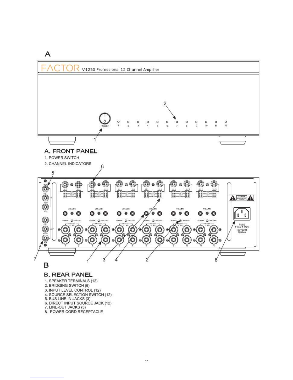
Quick Start: To get up and running quickly refer to DIAGRAM A on the next
page.
1. Place the V-1250 in a well ventilated area.
2. Connect speakers to the speaker output jacks on the back panel of the
V-1250 using good quality stranded copper speaker wire 16-12awg. Wire the – or
negative amplifier terminal to the -/negative speaker terminal and the + or
positive amplifier terminal +/positive speaker terminal on each speaker.
Never connect more than two 8ohm speakers directly to the amplifier output
terminals in normal mode and never connect more than one 8ohm speaker
To each speaker terminal in bridge mode.
3. Connect an input source like an iPod, CD/DVD player or other music
player to either the bus line input (see #5 next page) or any zone input
(see #6 next page). Set the input selector switch on each zone to correspond
With your input source connection.
4.Once all your audio connections are made, plug in the AC power cord into a AC
110-115V 60 Hz power outlet.
5. Press the front panel power button to the ON position.
6.Start your music source and then adjust the back panel volume control by
turning the control clockwise to increase the input level or counter clockwise to
decrease the input level to achieve the desired volume level.
7. It is common to use a volume control like the Factor Electronics
VC-150 in each zone to control the volume locally. When using the Factor
Electronics X-Music as a source the zone volume can be controlled directly from
the iPod or hand-held music player.
Refer to Diagram A on the next page:
[email protected] www.factorelectronics.com
Page 4
Page 5
Front Panel Operations and Connections
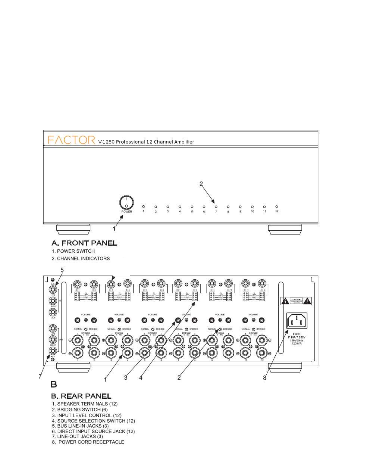
1. Power Switch- The POWER switch applies power to the amplifier and also activates the
power standby mode. The amplifier will be in standby mode and ready to play music in any zone
while minimizing AC current draw when not in use. It is possible to leave the amplifier POWER switch
in the ON position all the time. However we recommend turning the POWER switch to the OFF
position when the amplifier will not be used regularly or for a longer period of time.
It is possible to automate your ON/OFF times using the Factor Electronics Powersaver. This
Insures the least amount of power consumption, maximum protection and longer life of the product.
2. Channel Indicators The LED channel indicators light when music is playing in any zone.
[email protected] www.factorelectronics.com
Page 6
Rear Panel Operations and Connections
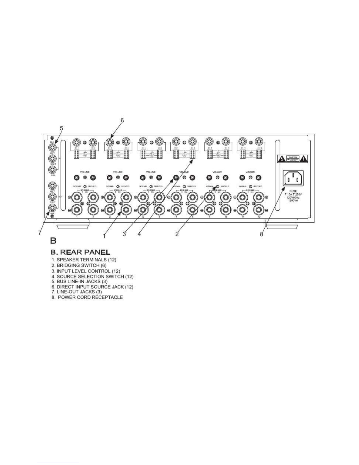
1. Speaker Terminals- Connect your speaker wires here using good quality stranded copper
speaker wire minimum 16 – 12awg. When the amplifiers are in normal mode you can safely
connect one or two 8ohm speakers to each speaker terminal. When connecting two 8ohm
speakers wired in parallel to each terminal the speaker impedance will be 4ohms. This is the
minimum impedance of each amplifier. Never exceed a 4ohm impedance on any amplifier
output. This will damage the amplifier and void the warranty. It is possible to bridge two
amplifier channels together to double the output power. In this case the minimum impedance
will be 8ohms. Never connect more than one 8ohm speaker to each amplifier output terminal
when the amplifier is in bridge mode.
2. Bridge Switch- The bridge switch combines two amplifier channels into one higher power
amplifier channel. The minimum impedance of a bridged amplifier channel is 8ohms.
Never connect more than one 8ohm speaker to a bridged amplifier channel. Also note that only
odd/even amplifier channel can be bridged together. The following amplifier channels can be bridged:
Bridgeable amplifier channels: 1&2, 3&4, 5&6, 7&8, 9&10, 11&12.
3. Input Level Control- These rotary volume controls provide input level adjustments for each
amplifier channel. Use these controls to match the desired volume level in each zone.
4. Source Selection Switch- The source selection switches provide independent source selection
for each amplifier channel. The possible selections include the following:
- IN- (RCA jack directly above each channel)
-LEFT- (Left BUS input)
-RIGHT- (Right Bus input)
-AUX- (Mono AUX Bus input)
NOTE: It is possible to select either IN or LEFT or RIGHT and AUX. In this example
the AUX input would be used for paging and the other selected input would be used for
Music. Both inputs would be broadcast in the selected zone.
[email protected] www.factorelectronics.com
Page 7
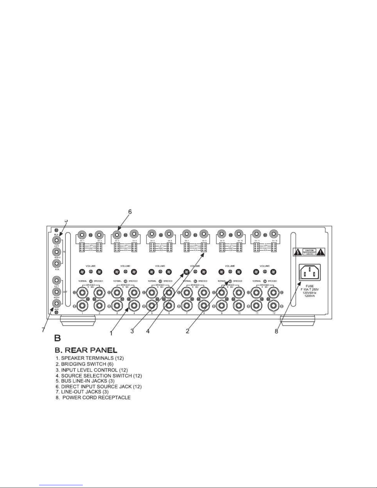
Rear Panel Operations and Connections:
5. Bus Line In Jacks- Connect an input source to the Bus Line In Jacks. Now select which
amplifier channels will broadcast the Bus Line In source by selecting either LEFT or RIGHT
Or AUX using the source selection switches provided on each amplifier channel.
6. Direct Input Source Jack- Connect an input source to the Input Source Jack. Now select
IN using the source selection switch on the corresponding amplifier channel.
7. Line Out Jacks- The Line Out Jacks route the source connected to the Line In Bus jacks
to the line output connectors. These jacks can be used in multiply ways. The most common
connection would be to add an additional V-1250 amplifier to expand your system to more zones.
These Jacks can also be used to connect the V-1250 to other amplifiers like receivers,
powered sub-woofers, music on hold inputs etc.
8. Power Cord- Plug the supplied AC power cord in here. Only use the factory supplied power
cord with the V-1250.
[email protected] www.factorelectronics.com
Page 8
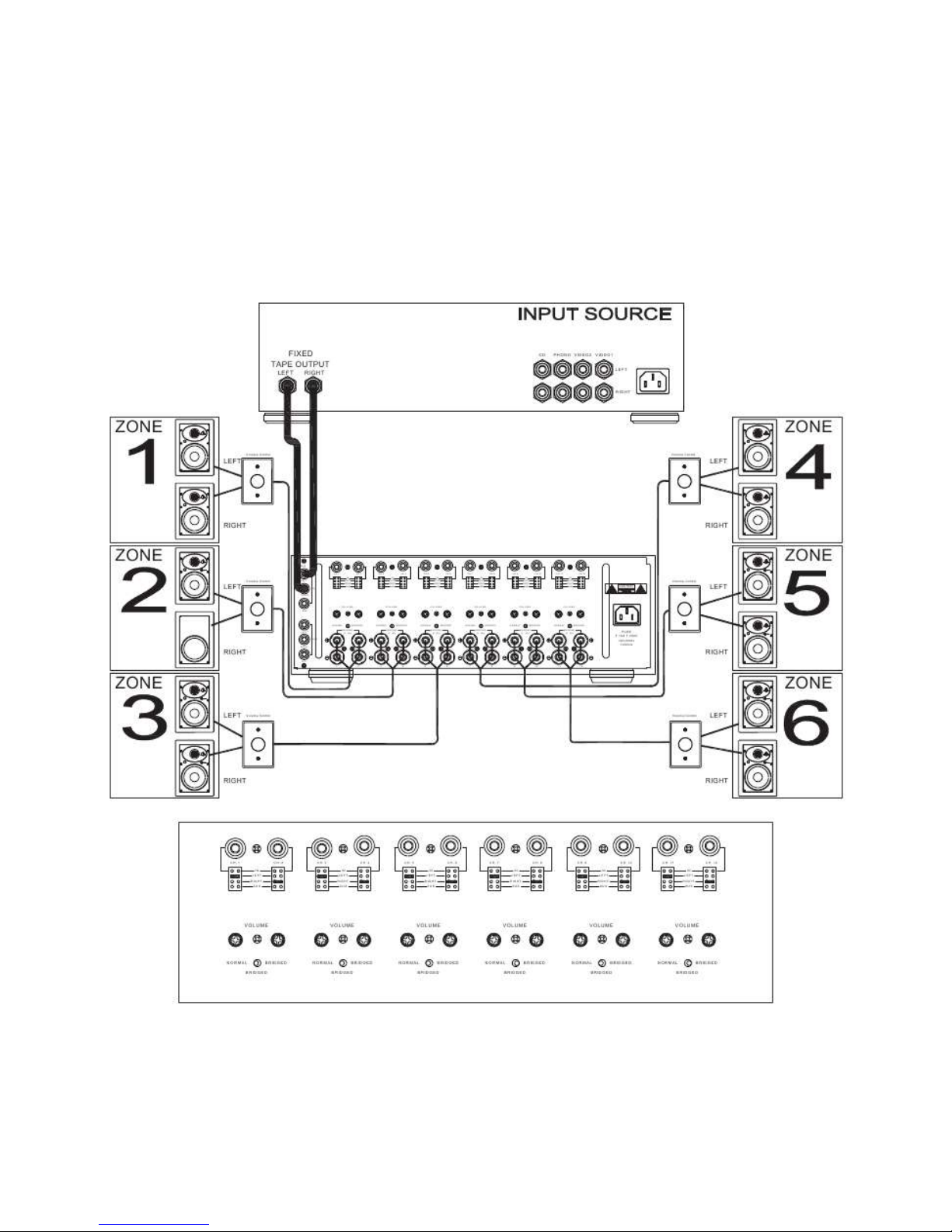
Single Source To Six Zones Connections:
This is an example of a single source setup providing music to six zones using Factor Electronics
VC-150 volume controls in each zone to control local volumes.
[email protected] www.factorelectronics.com
Page 9
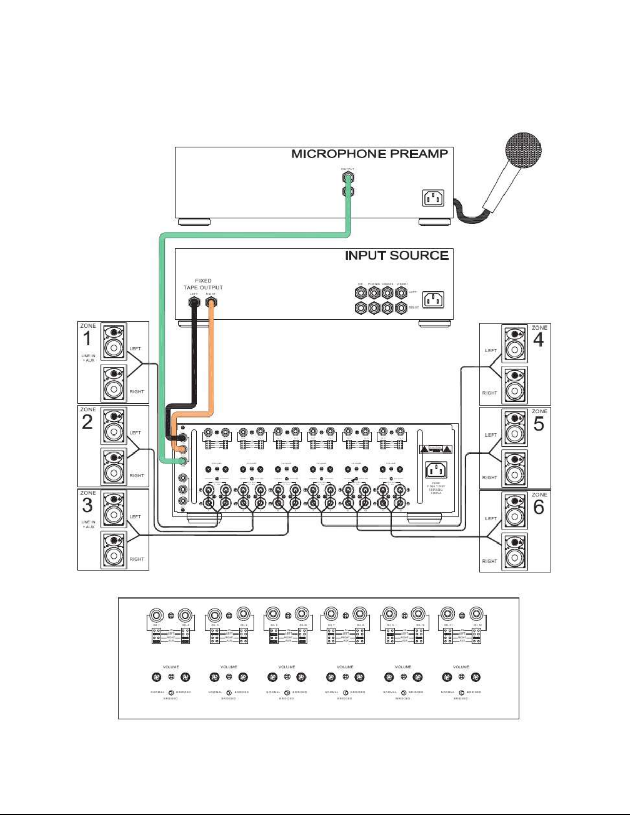
Single Source To Six Zone Connections Plus Microphone Paging:
This is an example of a single source setup providing music to six zones plus microphone paging
to six zones. In this setup the volumes are controlled by the microphone pre-amp and the input
source.
[email protected] www.factorelectronics.com
Page 10
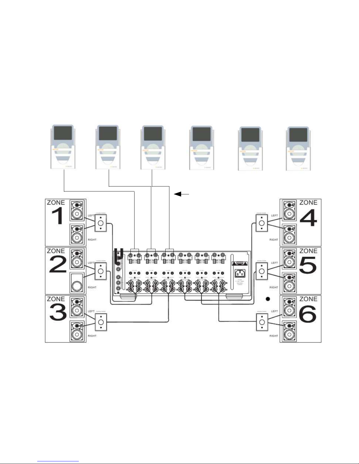
Six X-Music Sources To Six Zone Connections:
This is an example of six individual X-Music iPod sources providing independent music to six
zones with individual volume control using the Factor Electronics VC-150 volume controls.
The stereo output of each X-Music is connected to the IN jacks for each zone. Additional
volume control is provided directly from the iPod level control and in some cases the VC-150
Is not used. This is a great setup when a separate music source for each zone is required.
Repeat x 6
[email protected] www.factorelectronics.com
Page 11

V-1250 Specifications:
Amplifier Channels 12 independent amplifiers
AC Input Voltage 120V/240V Switchable
Amplifier Type Class A/B
Current @ VIN=0 0.05A
Current @ Auto/On/Off 0.018A
Output Power @ 8ohms 50 Watts RMS
Max Output Power @ 8ohms 55 Watts RMS
Noise <-60dB
Frequency Response (+/-3dB) 20Hz - 20kHz
T.H.D.@ Full Power 0.03%
Input Sensitivity 620mV
Load Impedance 8 ohms
Automatic Power On/Off Yes
Automatic-On Sensitivity < 15mVrms
Automatic-Off Time Delay >25 minutes
Thermal Protection 75 Degrees Celsius
Short Circuit Protection Yes Front Panel LED Flash
Dimensions W x H x D 16.625” x 5.5” x 15.75”
Dimensions W x H x D mm 423 x 140 x 400mm
Shipping Weight 45lb/20.5kg
In an effort to constantly provide our valued customers with the latest advancements in technology,
Factor Electronics specifications are subject to change from time to time without notice.
[email protected] www.factorelectronics.com
Page 12
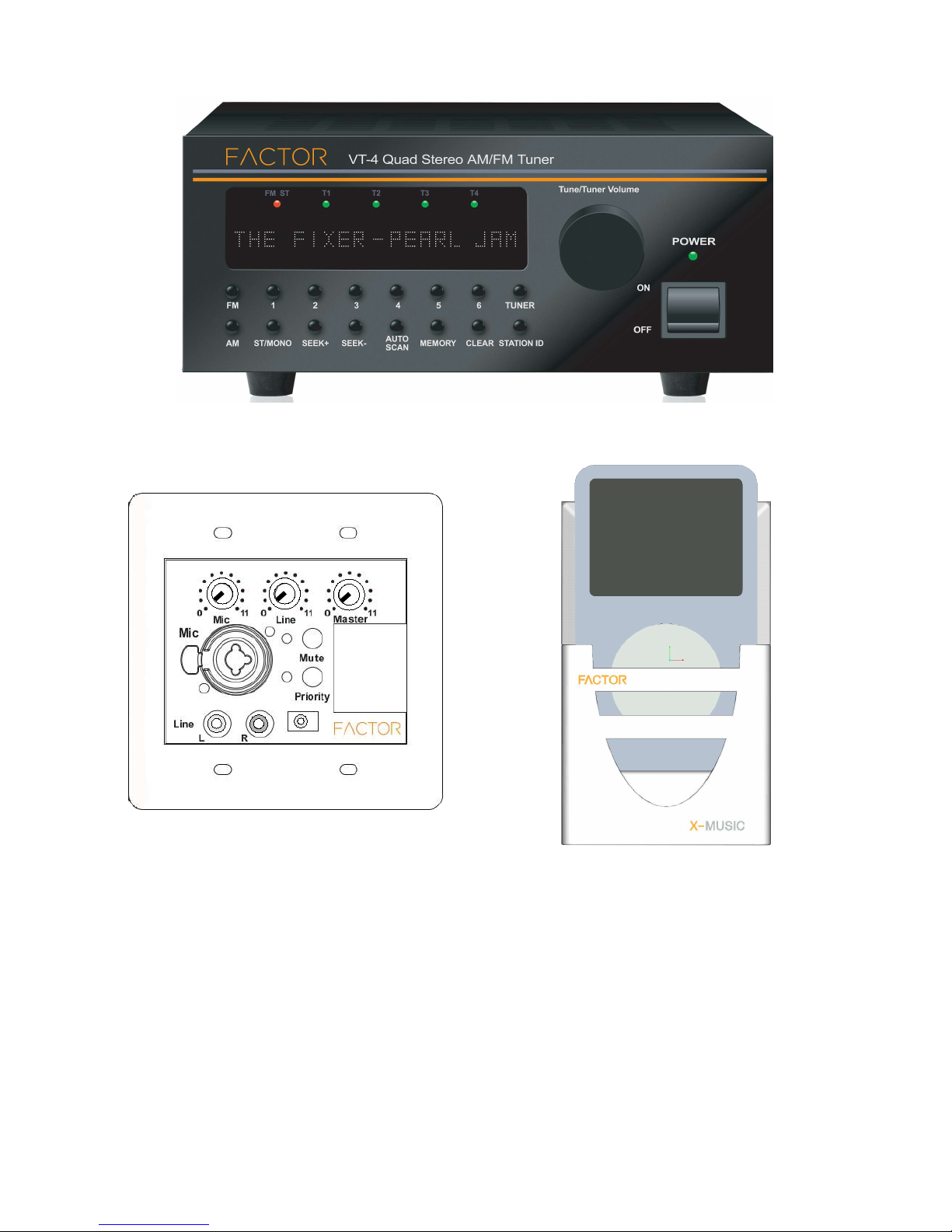
Factor Electronics V-Series Amplifier Accessories
VT-1 & VT-4 Digital AM/FM Tuners With RBDS
V-RVC-PRO
In-wall mic/line pre-amp
Contact Information
Factor Electronics
#108, 19232 Enterprise Way
4159 McConnell Crive Burnaby B.C. Canada V5A-3J7
Warranty
Factor Electronics amplifiers are warranted to be free from defects in workmanship and materials
for a period of three (3) years without charge for parts or labour. This warranty applies only to the
original owner. The owner’s responsibilities are to provide proof of purchase and transportation to
the dealer the unit was purchased from or transportation to Factor Electronics. This warranty does
not apply to units that have been subject to misuse, abuse, neglect or improper installation, and
does not apply to repairs or alterations by unauthorized personnel. This warranty specifically
excludes responsibility for consequential damage.
Retention of your dated ORIGINAL BILL OF SALE is required to obtain service under the terms of
the warranty.
[email protected] www.factorelectronics.com
X-Music
In-wall iPod dock
 Loading...